1
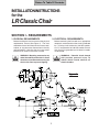
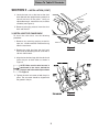
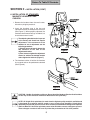
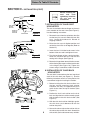
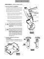
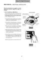
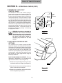
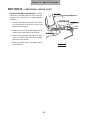
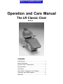
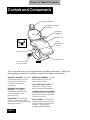
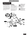
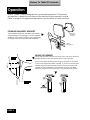
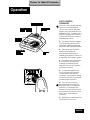
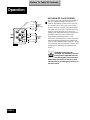
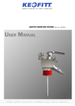
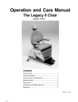
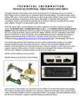
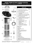
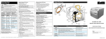
Go To Operation Section INSTALLATIONINSTRUCTIONS for the LR Classic Chair SECTION I - REQUIREMENTS 1. PHYSICAL REQUIREMENTS ................................................................................... 1 2. ELECTRICAL REQUIREMENTS ............................................................................. 1 SECTION II - INSTALLATION 1. UNPACKING THE CARTONS................................................................................... 2 2. UNPACKING THE CHAIR ......................................................................................... 2 3. INSTALLING THE CHAIR BACK .............................................................................. 3 4. REMOVING CHAIR FROM PALLET ......................................................................... 4 5. INSTALLATION OF PLATFORM COVERS ............................................................... 4 6. INSTALLATION OF STANDARD MAGNETIC HEADREST AND CUSHION ............ 5 7. INSTALLATION OF CHAIR SEAT UPHOLSTERY .................................................... 6 8. INSTALLATION OF CHAIR BACK UPHOLSTERY ................................................... 6 9. INSTALLATION OF ARMREST ................................................................................. 7 10. INSTALLATION OF OPTIONAL EQUIPMENT .......................................................... 7 SECTION III - OPERATIONAL CHECKS 1. FOOT CONTROL OPERATION ................................................................................ 8 2 MEMBRANE "TOUCH PAD" CONTROL PANEL ...................................................... 9 3. LIMIT SWITCH OPERATION AND SETTINGS......................................................... 9 SECTION IV - FINAL CHECK LIST FINAL CHECK LIST...................................................................................................... 11 003-1231-00 Rev. C Style F* Return To Table Of Contents Return To Table Of Contents INSTALLATIONINSTRUCTIONS for the LR Classic Chair SECTION I - REQUIREMENTS 1. PHYSICAL REQUIREMENTS 2. ELECTRICAL REQUIREMENTS: Before installing the chair ensure that the physical requirements are met (See Figure 1). The chair should be at least 18 inches from the nearest wall, cabinet, or any permanent fixture when in the fully reclined position. Note that the chair seat moves forward 4-1/2 inches as the base is raised. Before connecting the line cord to an appropriate receptacle, make certain that the circuit is protected by a 15-amp circuit breaker for 120-VAC models, or a 7.5-amp breaker for 240-VAC models. Ensure that all wiring is grounded and all electrical codes are observed. WARNING - Mounting accessories my affect the stability of the chair. In these situations we recommend securing the chair to the floor to prevent tipping. WARNING - Potential shock hazard with possible personal injury. To reduce shock hazard, observe all electrical codes. Figure 1 1 Return To Table Of Contents SECTION II - INSTALLATION 1. UNPACKING THE CARTONS 2. UNPACKING THE CHAIR The chair is shipped in two cartons, one large carton and a smaller carton, containing the following items: Use the following procedure to disconnect the chair from the pallet. Leave the chair on the pallet until the chair back has been installed. LARGE CARTON z Chair mounted on a pallet with backrest disconnected z Plastic bag containing 3 platform covers and installation hardware z Installation instructions (this manual) and operator’s manual z Foot Control 1. Locate the foot controller and remove and discard the packing material. 2. Locate the two socket head cap screws and washers that secure the back of the chair to the pallet brace (see Figure 2). Using a 5/16inch allen wrench, remove the two screws and washers. SMALL CARTON z Seat Cushion z Back Cushion z A Set of Armrests z Clear Vinyl Toeboard Cover z Headrest and Cushion z Hardware Kit 3. Locate the two hex screws and two washers that secure the pallet cleat to the pallet, as shown in Figure 2. Using an adjustable wrench, remove the two screws and washers. Remove and discard pallet brace and cleat. Check for signs of damage to either carton or to the contents and that all items listed above are present. If there is any evidence of damage due to shipping or if any of the items is missing from the cartons, notify the shipper at once. Be careful not to discard any small parts or instruction sheets with the packing material. Figure 2 2 Return To Table Of Contents SECTION II - INSTALLATION (CONT) 4. Locate the two nuts at the front of the chair base (beneath the upright housing cover) that secure the chair to the pallet. Using an adjustable wrench, remove the nuts, washers and bolts (see Figure 3). UPRIGHT HOUSING COVER 5. Remove packaging material from the chair back and discard. 3. INSTALLING THE CHAIR BACK NUT AND WASHERS To install the chair back, use the following procedure: AF1011 1. Remove any remaining packing materials, tape, etc., and discard them. Remove the tag from the seat frame. PALLET CHAIR BASE Figure 3 2. Remove the pivot pins from the chair back clevis ends by loosening the set screw with a 1/8-inch allen wrench. 4. Align the tow bar bearings with the clevis and insert the pins on both sides as shown in Figure 4. NOTE: Make sure the wire harness is positioned in the clevis, behind the pivot pin and in the cable clip as shown in Figure 4. 5. Tighten the each set screw to hold the pin in place. The set screw should be aligned with the groove in the pin. Figure 4 3 Return To Table Of Contents SECTION II - INSTALLATION (CONT) 4. REMOVING CHAIR FROM PALLET SEAT HINGES After the preceding steps are completed, the chair may be removed from the pallet and placed in the desired position on the floor. Use the following procedure: 1. Unwrap the foot control and discard the packing materials. MOTOR BARS 2. Grasp the chair by the chair back and/or seat frame and carefully slide the chair from the pallet onto the floor and into position. Figure 5 WARNING: Do not attempt to lift the chair by the motor bars. The motor shaft will be damaged (See Figure 5). 5. INSTALLATION OF PLATFORM COVERS Before installing the platform covers, make sure the power cord is plugged in to an appropriate outlet. Be sure the foot control is unwrapped and ready for use (Refer to Section III, Para. 2). Use the foot control to raise the chair to its full up position. Install the platform covers using the following instructions: 1. Remove the four phillips head screws from the parts bag for use on platform covers. 2. Position the center platform cover in place as shown (See Figure 6). 3. Install the left and right platform covers making sure they trap the center platform cover in place. Secure each side cover with two phillips head screws. Figure 6 WARNING: After the covers are installed, check the Safety Bail (See Figure 6) and make sure it moves freely up and down to operate the base safety switch. This is important for safe and proper chair operation. 4 Return To Table Of Contents SECTION II - INSTALLATION (CONT) 6. INSTALLATION OF STANDARD MAGNETIC HEADREST AND CUSHION 1. Remove the headrest from the small carton; discard any shipping materials. 2. Insert the headrest tang in the slot and adjustment bracket at the top of the chair back (See Figure 7). When properly adjusted, the headrest should move freely up and down, but should not move on its own. The adjusting bracket tension is pre-set at the factory and should not require adjustment. If the movement of the headrest is out of adjustment use the following procedure: 1) Using an open end wrench, loosen the two locknuts on the side of the adjustment bracket. 2) Then, loosen or tighten the adjustment screws to achieve the desired tension and re-tighten the locknuts (Figure 7). Figure 7 3. The headrest cushion is held to the headrest by a magnet and can be positioned as desired (See Figure 8). Figure 8 CAUTION: Handle all upholstery with care. Do not bend the Headrest, Back or Seat Cushions as this may cause excessive wrinkles or distortion of the upholstery. NOTE: All Knight Chair upholstery is made from the highest quality materials available and is designed for maximum patient comfort, easy cleaning and durability. Knight Chair upholstery will provide years of service when correctly maintained according to the Operator and Care Manual. Like all fine upholstery some minor wrinkles, waves or changes may occur. These changes are natural and in no way effect the performance or life of the product. 5 Return To Table Of Contents SECTION II - INSTALLATION (CONT) Before installing the seat and back upholstery, install the LR unit and any accessories AF1012 SEAT 7. INSTALLATION OF CHAIR SEAT UPHOLSTERY HEX SCREW IN SEAT BOTTOM HINGE IN VERTICAL POSITION SEAT FRAME The seat is attached to the two hinges on the main cross member of the seat frame (See Figure 5). Use the following instructions: Figure 9 1. Remove the seat from the upholstery box (the smaller box); be sure to handle the seat with care. Locate the hardware kit. Discard all shipping materials. AF1013 2. Raise the chair up to its highest position and recline the chair back to 45 degrees (Refer to Section III). 3. Insert the four 1/4-20 hex head screws in the bottom of the seat and hand tighten 2 turns. SCREWS SLIDING INTO HINGE SLOTS 4. Turn the two hinges up into a vertical position. Lower the seat onto the chair with the seat resting on the hinges (See Figure 9). Figure 10 5. Rotate the hinges down toward the hex screws while allowing the screws to slide into the slots in the hinges (See Figure 10). Tighten the screws using a screwdriver or 3/8 inch socket. 8. INSTALLATION OF CHAIR BACK UPHOLSTERY The seat back is mounted over the four large head studs in the chair back (see Figure 11). Use the following instructions after first raising the back to a convenient height for installing the cushion. 1. Before installing the chair back cushion, turn the four cushion mounting studs counter clockwise until they are approximately 5/16 to 3/8 inches from the top of the boss (See Figure 11). 2. Position the chair back cushion on the chair back and align the four cushion mounting studs with the holes in the chair back cushion (See Figure 11). 3. With the chair back cushion held tight against the chair back, push downward to lock the cushion into place. Figure 11 6 4. Secure the velcro strips on the cushion skirt to the velcro strips on the chair back. Smooth the skirt out with your hand to remove any wrinkles. Return To Table Of Contents SECTION II - INSTALLATION (CONT) 9. INSTALLATION OF ARMREST The armrests are held in position by a set screw located in the back of the hip post. A pivot mechanism allows the armrest to swing out, while the armrest post remains stationary. Use the following procedure to install the armrests: 1. Unpack the armrests and discard all packing materials. The armrests are secured to the bottom of the small carton (Figure 12). 2. Insert the armrest post in the hip post, making sure that the right and left hand mounting positions are observed (See Figures 13 & 14). 3. Position the armrest parallel to the side of the chair and tighten the set screw (See Figure 13). NOTE: The set screw must be tighten with considerable force to keep the armrest post from turning. The armrest should pivot only at the pivot mechanism. NOTE: We recommend disabling the swing out feature on the side of the chair opposite patient access. To lock the armrest and disable the swing out feature, remove the pivot screw and washer on the underside of the armrest and turn the stop plate 900. Replace the pivot screw and washer and tighten (See Figure 14). Figure 13 10. INSTALLATION OF OPTIONAL EQUIPMENT If optional equipment was ordered with the chair, it should be installed in accordance with the instructions included in the optional equipment package. Figure 14 Figure 12 7 Return To Table Of Contents SECTION III - OPERATIONAL CHECKS (CONT) When the installation is complete, certain operational checks should be made, as follows: 1. FOOT CONTROL OPERATION NEUTRAL POSITION (for manual operation) The foot control (See Figure 15) duplicates the function of the Membrane “Touch Pad” panel, but is actuated by the operator’s foot. Consisting of a selector (toggle) switch and a control disk, the foot control is operated as follows: YELLOW/ EXIT POSITION GREEN/ AUTOMATIC OPERATE POSITION SELECTOR (TOGGLE) SWITCH z The Selector Switch toggles from its Neutral position to the Automatic Operate (green) or Automatic Exit (yellow) positions z The Automatic Operate position is actuated by momentarily pressing and releasing the selector switch to the position indicated in green. CONTROL DISK ILLUSTRATION OF DISK FUNCTIONS z The Automatic Exit position is actuated by momentarily pressing and releasing the selector switch to the position indicated in yellow. Figure 15 z To manually position the chair, actuate and hold the control disk to the desired quadrant. For example; sliding the disk to the left will actuate the back-down position. z Two functions can be actuated simultaneously by sliding the disk in a diagonal direction. F o r example, Figure 16 illustrates the simultaneously actuation of the back-down and base-up functions. z Releasing disk stops the movement of the chair. Figure 16 8 Return To Table Of Contents SECTION III - OPERATIONAL CHECKS (CONT) 2. MEMBRANE "TOUCH PAD" CONTROL PANEL Automatic Exit Function The Membrane “Touch Pad” Control panel is located in the center of the instrument head. The panel allows the operator to control the position of the chair from the instrument head, as well as by use of the foot control. The panel, shown in Figure 17, allows the operator to incline or recline the chair back or move the seat up or down by pressing the appropriate touch pad switch, holding it until the chair or back has achieved the desired position. The Automatic Operate/Exit Function switches are programmed settings that adjust the chair to the predetermined position. These two switches are actuated by momentarily pressing and releasing the appropriate switch. Automatic Operate Function TOUCH AND RELEASE Base UP Back UP Back DOWN PRESS AND HOLD Base DOWN AF1012 WARNING: Once they are actuated, the Automatic Exit and the Automatic Operate functions may be stopped by momentarily depressing any switch on the touch pad control panel or actuating any function on the foot control. Figure 17 BASE COVER 3. LIMIT SWITCH OPERATION AND SETTINGS The automatic chair control system provides Automatic Operate and Automatic Exit functions. The Automatic Exit function (yellow switch position on foot control; top membrane touch pad position) is preset at the factory and not adjustable. The Automatic Operate position (green switch position on foot control; second from top membrane touch pad position) is readily programmed using the following procedures: CLOCKWISE CAM COUNTER CLOCKWISE BASE PROGRAMMING PROCEDURE - The base adjustment is provided by a cam located on the right side of the base cover (see Figure 18). 1. Rotate the cam protruding from the base cover counter clockwise until it stops (see Figure 18). AF1015 2. Move the chair base to the desired position by means of the touch pad switches. Figure 18 3. Rotate the cam clockwise until the switch clicks, which completes the procedure. 9 Return To Table Of Contents SECTION III - OPERATIONAL CHECKS (CONT) BACK PROGRAMMING PROCEDURE - The back adjustment is located under the seat on the right side of the chair (see Figure 19). Use the following procedure. 1. Loosen the thumbscrew (see Figure 19). Move the actuator plate all the way to the left and tighten the thumbscrew.. 2. Move the chair back to the desired position by means of the manual touch pad switches. 3. Loosen the thumbscrew (see Figure 19), then move the actuator plate until the front edge contacts the microswitch. 4. When the actuator plate is in position, tighten the thumbscrew. Figure 19 10 Return To Table Of Contents SECTION IV - FINAL CHECK LIST When all the assembly and installation procedures are completed, the chair should be checked out in accordance with the following check list to ensure that assembly is complete and that all controls function properly. Check all controls for proper operation. Check operation of safety bail. Check chair rotation, stops and locking functions. Check the armrests to ensure proper functioning and that the armrest post is secured an will not move. Be sure that the cushions are properly installed and the toeboard cover is in place. Check that the platform covers are installed. Be sure that all optional equipment has been installed. Check that all shipping tape and other packaging materials have been removed and disposed of. Make sure that the chair has been cleaned and that all dirt and finger prints have been removed. Be sure the person who will operate the chair receives the operators manual and any other appropriate information or instructions. ® CON FORM S TO UL STD. 544 CERTIFIED TO CA N / CSA - C22.2 N O. 125-M 1984 11 Return To Table Of Contents NOTES 12 Return To Table Of Contents Return To Table Of Contents Midmark Corporation P O Box 286 60 Vista Drive Versailles Ohio 45380-0286 www.midmark.com Phone: 937-526-3662 Fax: 937-526-5542 Return To Installation Section Operation and Care Manual The LR Classic Chair Model N CONTENTS Introduction ......................................................... 1 Label Definitions .................................................. 1 Controls and Components ................................ 2 Requirements ...................................................... 3 Operation ............................................................ 4 Limit Switch Operation and Settings ................. 7 Cleaning and Maintenance .............................. 8 Warranty ............................................................... 9 Return To Table Of Contents Return To Table Of Contents Introduction This publication is a user's manual containing all the information you will need to operate and care for your LR Classic Chair. Before operating your chair, please read this manual to become familiar with its special features and functions. The LR Classic Dental Chair provides exceptional comfort and support during dental procedures. The chair is fully adjustable, from upright to beyond horizontal, to ensure maximum patient comfort and ready access to the patient by the operator. Designed for reliability and simplicity of function, your chair will provide you with years of service with a minimal amount of maintenance. Label Definitions Hazards which result in severe personal injury or death. Hazards which could result in personal injury. Hazards which could result in equipment or property damage. Alert user to pertinent facts and conditions. “DANGER - EXPLOSION HAZARD - DO NOT USE THIS EQUIPMENT IN THE PRESENCE OF FLAMMABLE ANESTHETICS” ® CON FORM S TO UL STD. 544 CERTIFIED TO CA N / CSA - C22.2 N O. 125-M 1984 PAGE 1 Return To Table Of Contents Controls and Components M A G N E T IC H E A D R E S T BACKREST LUM BAR SUPPO RT S W IN G O U T ARMRESTS B U C K E T S E AT V IN Y L TO E B O A R D COVER U N IT M O U N TE D C H A IR C O N T R O L S A F E T Y B A IL A F1 0 1 7 C H A IR B A S E F U L L F U N C T IO N FOOT CO NTROL The components and controls identified are described below. Read the descriptions carefully to familiarize yourself with these components MAGNETIC HEADREST - provides comfortable support for the patients head and neck throughout the dental procedure. BACKREST AND LUMBAR SUPPORT - a contoured seamless seat and lumbar cushion support for the patients back. BUCKET SEAT - The seamless seat is contoured to ensure patient comfort throughout the dental procedure. PAGE 2 SWING-OUT ARMRESTS - provide easy access to or from the chair on either side. VINYL TOEBOARD COVER - fits over the end of the bucket seat to protect the upholstery. UNIT MOUNTED CHAIR CONTROL Located on the unit head, this panel duplicates the functions of the foot control. FOOT CONTROL - controls the proper positioning of the chair. It also provides two automatic positions - auto exit and programmable operation. Return To Table Of Contents Requirements PHYSICAL REQUIREMENTS The illustration below shows the basic space requirements of your LR Classic Chair. The chair should be at least 18 inches from the nearest wall, cabinet, or any permanent fixture when in the fully reclined position. Note that the chair seat moves forward 4-1/2 inches as the base is raised. ELECTRICAL REQUIREMENTS: Before connecting the line cord to an appropriate receptacle, make certain that the circuit is protected by a 15amp circuit breaker for 120VAC models, or a 7.5-amp breaker for 240-VAC models. Ensure that all wiring is grounded and all electrical codes are observed. WARNING - Potential shock hazard with possible personal injury. To reduce shock hazard, observe all electrical codes. WARNING - To disconnect power to the chair, you must unplug the power cord from the electrical outlet. This equipment is rated Class I, Type B PAGE 3 Return To Table Of Contents Operation The LR Classic Chair is designed for convenient operation. This section will explain in detail the functions of the electrical and manual controls. Refer to page 2 for a general description and location of these controls. STANDARD MAGNETIC HEADREST The headrest height can be easily adjusted by simply pulling out or pushing in on the headrest assembly. The cushion is held to the headrest by a magnet and can be positioned as desired. MAGNETIC HEADREST CUSHION HEIGHT ADJUSTMENT SWING OUT ARMREST Grasp the armrest and pull out away from the chair. With the patient seated, push the armrest back until it latches. We recommend disabling the swing out feature on the side of the chair opposite patient access. To lock the armrest and disable the swing out feature, remove the pivot screw and washer on the underside of the armrest and turn the stop plate 900. Replace the pivot screw and washer and tighten. PAGE 4 Return To Table Of Contents Operation FOOT CONTROL OPERATION The foot control duplicates the function of the Membrane Touch Pad panel (See next page), but is actuated by the operators foot. Consisting of a selector (toggle) switch and a control disk, the foot control is operated as follows: l The Selector Switch toggles from its neutral position to the automatic operate (green) or automatic exit (yellow) positions. l The Automatic Operate position is actuated by momentarily pressing and releasing the selector switch to the position indicated in green. l The Automatic Exit position is actuated by momentarily pressing and releasing the selector switch to the position indicated in yellow. l To manually position the chair, actuate and hold the control disk to the desired quadrant. For example, sliding the disk to the left will actuate the back-down position. l Two functions can be actuated simultaneously by sliding the disc in a diagonal direction. For example, the illustration to the left shows the simultaneous actuation of the back-down and base-up functions. l Releasing the disk stops the movement of the chair. PAGE 5 Return To Table Of Contents Operation UNIT MOUNTED CHAIR CONTROL A u to m a tic E x it F u n ctio n A u to m a tic O p e ra te F u n ctio n TO UC H AND RELEASE Base UP Back UP Back DO W N Base DO W N A F1 0 1 2 PRES S AND HOLD This touch pad control panel is located on the unit head allowing the operator to control the position of the chair from the unit as well as by use of the foot control and chair back controls. The panel allows the operator to incline or recline the chair back or move the seat up or down by pressing the appropriate touch pad switch, holding it until the chair or back has achieved the desired position. The Automatic Operate/Exit Function switches are programmed settings that adjust the chair to the predetermined position. These two switches are actuated by momentarily pressing and releasing the appropriate switch. WARNING: Once they are actuated, the Automatic Exit and the Automatic Operate functions may be stopped by momentarily depressing any switch on the touch pad control panel or actuating any function on the foot control. PAGE 6 Return To Table Of Contents Limit Switch Operation and Settings The automatic chair control system provides Automatic Operate and Automatic Exit functions. The Automatic Exit function (yellow switch position on foot control; top membrane touch pad position) is preset at the factory and is not adjustable. The Automatic Operate position (green switch position on foot control; second from top membrane touch pad position) is readily programmed using the following procedures: BASE COVER BASE PROGRAMMING PROCEDURE - The base adjustment is provided by a cam located on the right side of the base cover. C L O C K W IS E CAM 1. Rotate the cam protruding from the base cover counter clockwise until it stops. 2. Move the chair base to the desired position by means of the touch pad switches. COUNTER C L O C K W IS E 3. Rotate the cam clockwise until the switch clicks, which completes the procedure. A F1 0 1 5 BACK PROGRAMMING PROCEDURE - The back adjustment is located under the seat on the right side of the chair. 1. Loosen the thumbscrew. Move the actuator plate all the way to the left and tighten the thumbscrew. 2. Move the chair back to the desired position by means of the manual touch pad switches. 3. Loosen the thumbscrew, then move the actuator plate until the front edge contacts the microswitch. 4. When the actuator plate is in position, tighten the thumbscrew. PAGE 7 Return To Table Of Contents Cleaning and Maintenance After installation has been completed, thoroughly clean the chair and upholstery. After the initial cleaning, it should be cleaned as necessary and at least weekly. Observe the following instructions. A NOTE ABOUT THE UPHOLSTERY: All Knight Chair upholstery is made from the highest quality materials available and is designed for maximum patient comfort, easy cleaning and durability. Knight Chair upholstery will provide years of service when correctly maintained according to the Operator and Care Manual. Like all fine upholstery some minor wrinkles, waves or changes may occur. These changes are natural and in no way effect the performance or life of the product. CLEANING THE UPHOLSTERY When cleaning upholstery, it is suggested that you use all recommended commercial cleaning agents in an inconspicuous spot to check for potential damage to the upholstery material before applying to the entire area to be cleaned. For everyday cleaning, we recommend a mild dish washing liquid, warm water, and a damp white cloth. Spraying upholstery with a silicone-based coating will improve luster and soil resistance. CLEANING PAINTED SURFACES The painted metal surfaces are covered in durable, powdercoated paint which is resistant to scratching and scuffing. It may be cleaned with a clean cloth dampened with mild, soapy water. To add luster and dirt resistance, use a presoftened car wax PAGE 8 RECOMMENDED INFECTION CONTROL PRODUCTS The disinfectant/cleaner products that we have tested and recommend for our upholstery, painted items and plastic covers are as follows: Cavicide distributed by E&D Dental Products Inc., Westfield, NJ Precise - Hospital Foam Cleaner Disinfectant manufactured by Caltech Industries, Inc., Midland, MI CAUTION: Follow manufacturer's directions for concentration and application of disinfecting material. Avoid prolonged application of any disinfectant/ cleaner products, because they may cause staining of upholstery material. TROUBLESHOOTING Only in case of no power to the chair should dental personnel attempt to remedy the problem. In this case, (1) make sure that the power cord is firmly plugged into the receptacle or (2) check that the main circuit breaker to the chair is turned on. CAUTION: All troubleshooting and maintenance on the chair should be performed by a qualified technician. Dental personnel must not attempt to perform any maintenance functions on the chair, attempt to replace any fuses or other electronic components, or attempt to gain access to the motors or other units. LUBRICATION After extended use your chair may require lubrication at pivot joints (i.e. chair back pivot joint). Lubricate the joints with a drop of light weight oil or silicone lubricant. Return To Table Of Contents Warranty WARRANTY Knight by Midmark products are warranted against defect in material and workmanship for a period of 2 years, unless otherwise indicated in writing, from the time of delivery. Exceptions: 1) "KINK-VALVE" module carries a 10 year warranty. 2) The original light bulb on a new light carries a 1 year warranty. 3) Accessories not manufactured by Knight are excluded (i.e. Fiber optic systems, Scalers, Electric micromotor systems, Curing light systems, X-ray viewers, etc.) 4) Replacement parts and accessories carry a 90 day warranty. Knight's sole obligation under the warranty is either to provide parts for the repair or to provide the replacement product (excluding labor and shipping). The buyer shall have no other remedy. All special, incidental and coincidental damage is excluded. Written notice of breach of warranty must be given to Knight within the warranty period. The warranty does not cover damage resulting from improper installation or maintenance, accident or misuse. The warranty does not cover damage resulting from the use of cleaning, disinfecting or sterilization chemicals and processes. No other warranties as to merchantability, fitness for use or otherwise are made. PAGE 9 Return To Table Of Contents Midmark Corporation P O Box 286 60 Vista Drive Versailles Ohio 45380-0286 www.midmark.com Phone: 937-526-3662 Fax: 937-526-5542