1
User Manual
ThaiEasyElec MP3 Embedded Module
Version 1.2
Revision History
Version
Date
Changes
1.2
1.1
4 June 2014
16 November 2013
1.0
3 October 2013
Wording Correction
Image chaged,
Usage with Arduino added
Original Version
Venus Supply Co., Ltd.
Page 1
User Manual of ThaiEasyElec’s MP3 Embedded Module (ETEE043)
The MP3 Module (ETEE043) was designed to be an easy to use, cost-effective MP3 playback
module. It uses BU94502AKS2 as the MP3 decoder which provides fine quality sound with 8 kHz –
48 kHz sampling rate. The user can use any MCU to control the module using parallel or serial
interface. With MP3 files stored on a SD card, the user can select a sound folder, select a file, start
playback and control play volume using simple serial or parallel commands. The SD card can be
as large as 32 GByte. The module is well suited many applications such as queuing system, voice
mail box, station announcement.
Venus Supply Co., Ltd.
Page 2
Features
-
Support stereo MP3 files
2 interface modes: serial and parallel
Support FAT32 and FAT16 file system
Accept micro SD Card with SDHC supported (maximum 32 GB)
Sampling rates: 8 kHz - 48 kHz.
- Accept 5 VDC power supply
- Use 20-pin 2.54mm-pitch header for interface
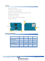
- Dimension: 35x51 mm
3.5 mm
35 mm
3.5 mm
51 mm
Electrical Characteristic
Parameter
Operating voltage
Operating current
Input voltage
Output voltage
Audio Distortion rate
Audio Dynamic range
Audio Max output level
Venus Supply Co., Ltd.
Min.
4
3.1
3.1
0.6
Typ.
5
0.005
90
0.75
Max.
9
150
5.3
0.05
-
Unit.
V
mA
V
V
%
dB
Vrms
Page 3
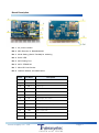
Board Description
No. 1
N0. 2
No. 3
No. 4
No. 5
No. 6
No. 7
No. 8
5V power indicator
MP3 Decoder IC, BU94502AKS2
Mode Setting (Serial / Parallel) for soldering
BUSY LED
MCU Debug Port
MCU, STM8S103
Micro-SD Card Socket
Interface Header, see detail below:
Pin No.
1-8
9
10
11
12
13
14
15
16
17
18
19
20
Pin Name
P0 – P7
VOLVOL+
RESERVE
RESERVE
BUSY
PL
RXD
TXD
HPR
HPL
GND
+5V
Venus Supply Co., Ltd.
Description
Data Input
Volume down
Volume up
Busy, low active
Trigger Input, low active
Serial port receiver input
Serial port transmitter output
Audio output right
Audio output left
Ground
5V Power input
Page 4
Note!!
BUSY Pin: BUSY is driven low on initialization state and when a file is being played. In all other
case, the pin is driven high.
PL Pin: PL is the trigger pin with low-level active. When asserted, the module read data from P0P7. It must be asserted when data on P0-P7 is ready.
How to use the module
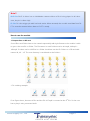
1. Prepare files on SD card
Sound files and folders have to be named sequentially with right format so the module is able
to get to the next file or folder. The file names in each folder must be 001.mp3, 002.mp3 …
199.mp3. So there can be 199 files in a folder. And there can be 15 folders on a SD card with
names: 02, 03 … 15. The root directory is considered as the folder 1.
- File ordering example
From figure above, there are 4 files and the file 017.mp3 is counted as the 3rd file. So the user
has to play it using command 0x03.
Venus Supply Co., Ltd.
Page 5
- Folder ordering example
From figure above, there are 5 folders including the root directory. The folder 11 is counted as the
4th folder, to get into it, use command 0xF4 (Change to folder 4).
As illustrated, it’s recommended to name all files and folders sequentially.
2. Select the operating mode (Serial / Parallel)
2.1 To use Parallel mode, M0 and M1 must be connected to GND as shown below (zero-ohm
resistors are used here):
*** By default, the module is configured in parallel mode ***
2.2 To use Serial mode, remove M0 and leave M1 connected to GND. See image below:
Venus Supply Co., Ltd.
Page 6
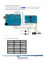
3. Control the module in Parallel mode
The module is controlled by Arduino UNO R3 (EADN014) for example. In parallel mode, 10 signals
are used for control: 8-bit data, PL and BUSY. Optionally, +VOL and –VOL can be connected to
switches for increasing or decreasing the volume directly.
Data In 8 Bits
BUSY PL
+5V
GND
Switch -Vol
Switch +Vol
HP_L HP_R
The connections are described below:
MP3 module
+5V
GND
P0–P7
BUSY
PL
VOL+
VOLHP_L
HP_R
Venus Supply Co., Ltd.
Pin
+5V
GND
D2-D9
A4
A5
Left
Right
Device
Arduino
Arduino
Arduino
Arduino
Arduino
Switch 1
Switch 2
Audio Jack
Audio Jack
Page 7
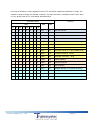
From the circuit above, control signals are P0-P7, PL and BUSY. Whenever that BUSY is “High”, the
module is ready to accept new parallel command. The user can send a command to P0-P7 then send
a “Low” strobe pulse on PL. Commands are listed below:
P7
0
0
…
1
1
1
…
1
1
1
1
1
1
1
1
…
1
P6
0
0
….
1
1
1
….
1
1
1
1
1
1
1
1
….
1
P5
0
0
…
0
0
0
…
1
1
1
1
1
1
1
1
…
1
Command Word
BIN
P4 P3 P2 P1 P0
0 0 0 0 1
0 0 0 1 0
… … …. …. …
0 0 1 1 1
0 1 0 0 0
0 1 0 0 1
… … …. …. …
0 0 1 1 1
0 1 0 0 0
0 1 0 0 1
0 1 0 1 1
0 1 1 0 0
0 1 1 1 1
1 0 0 0 1
1 0 0 1 0
… … …. …. …
1 1 1 1 1
Venus Supply Co., Ltd.
Function
HEX
0x01
0x02
…
0xC7
0xC8
0xC9
…
0xE7
0xE8
0xE9
0xEB
0xEC
0xEF
0xF1
0xF2
…
0xFF
DEC
001
002
…..
199
200
201
…..
231
232
233
235
236
239
241
242
…..
255
Play the first file
Play the second file
….
Play the 199th file
Set volume level to 0 (the lowest level)
Set volume level to 1
….
Set volume level to 31 (the highest level)
Increase volume by 1 level
Decrease volume by 1 level
Pause playback
Resume playback
Stop playback
Change directory to 01 (Root directory)
Change directory to 02
….
Change directory to 15
Page 8
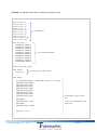
Example 1 In parallel mode, send a command to play 001.mp3.
const
const
const
const
const
const
const
const
const
const
int
int
int
int
int
int
int
int
int
int
P0 =
P1 =
P2 =
P3 =
P4 =
P5 =
P6 =
P7 =
BUSY
PL =
2;
3;
4;
5;
6;
7;
8;
9;
= A4;
A5;
1. Pin assignments
void set_port() {
pinMode(P0, OUTPUT);
pinMode(P1, OUTPUT);
pinMode(P2, OUTPUT);
pinMode(P3, OUTPUT);
pinMode(P4, OUTPUT);
pinMode(P5, OUTPUT);
pinMode(P6, OUTPUT);
pinMode(P7, OUTPUT);
pinMode(PL, OUTPUT);
pinMode(BUSY,INPUT);
}
2. Pins’ direction assignments
boolean cmd_stop =false;
void setup() {
set_port();
}
3. Call set_port() to set pins’ direction
void loop() {
if ((digitalRead(BUSY) == HIGH) && (cmd_stop == false)){
digitalWrite(P0,HIGH);
digitalWrite(P1,LOW);
digitalWrite(P2,LOW);
digitalWrite(P3,LOW);
digitalWrite(P4,LOW);
digitalWrite(P5,LOW);
digitalWrite(P6,LOW);
digitalWrite(P7,LOW);
delay(100);
digitalWrite(PL, LOW);
delay(100);
digitalWrite(PL, HIGH);
4. When BUSY is “High”, set data
pins
to 0x01 to the module and send “Low”
strobe pulse.
cmd_stop = true;
}
}
Venus Supply Co., Ltd.
Page 9
Code description:
void set_port() {
pinMode(P0, OUTPUT);
pinMode(P1, OUTPUT);
pinMode(P2, OUTPUT);
pinMode(P3, OUTPUT);
pinMode(P4, OUTPUT);
pinMode(P5, OUTPUT);
pinMode(P6, OUTPUT);
pinMode(P7, OUTPUT);
pinMode(PL, OUTPUT);
pinMode(BUSY,INPUT);
}
Function set_port () is used to initialized pins to be output or input.
void setup() {
set_port();
}
Function setup() is used for initialization.
void loop() {
if ((digitalRead(BUSY) == HIGH) && (cmd_stop == false)){
digitalWrite(P0,HIGH);
digitalWrite(P1,LOW);
digitalWrite(P2,LOW);
digitalWrite(P3,LOW);
digitalWrite(P4,LOW);
digitalWrite(P5,LOW);
4. When BUSY is “High”, set data
digitalWrite(P6,LOW);
digitalWrite(P7,LOW);
and send “Low” strobe pulse.
pins to 0x01 to the module
delay(100);
digitalWrite(PL, LOW);
delay(100);
digitalWrite(PL, HIGH);
cmd_stop = true;
}
}
When logic on BUSY pin becomes “High” and cmd_stop is false, a command 0x01 will be sent by
setting 8-bit data to 00000001 then send a “Low” strobe pulse on PL. Then cmd_stop is set to true.
This will command the module to play the first file once.
Venus Supply Co., Ltd.
Page 10
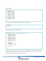
Example 2 In parallel mode, send a command to play 002.mp3 in folder 03.
const
const
const
const
const
const
const
const
const
const
int
int
int
int
int
int
int
int
int
int
P0 =
P1 =
P2 =
P3 =
P4 =
P5 =
P6 =
P7 =
BUSY
PL =
2;
3;
4;
5;
6;
7;
8;
9;
= A4;
A5;
1. Pin assignments
void set_port() {
pinMode(P0, OUTPUT);
pinMode(P1, OUTPUT);
pinMode(P2, OUTPUT);
pinMode(P3, OUTPUT);
pinMode(P4, OUTPUT);
pinMode(P5, OUTPUT);
pinMode(P6, OUTPUT);
pinMode(P7, OUTPUT);
pinMode(PL, OUTPUT);
pinMode(BUSY,INPUT);
}
2. Pins’ direction assignments
void send_CMD(unsigned char cmd) {
if( cmd&0x01 ) digitalWrite(P0, HIGH);
else digitalWrite(P0, LOW);
if( cmd&0x02 ) digitalWrite(P1, HIGH);
else digitalWrite(P1, LOW);
if( cmd&0x04 ) digitalWrite(P2, HIGH);
else digitalWrite(P2, LOW);
if( cmd&0x08 ) digitalWrite(P3, HIGH);
else digitalWrite(P3, LOW);
if( cmd&0x10 ) digitalWrite(P4, HIGH);
else digitalWrite(P4, LOW);
if( cmd&0x20 ) digitalWrite(P5, HIGH);
else digitalWrite(P5, LOW);
if( cmd&0x40 ) digitalWrite(P6, HIGH);
else digitalWrite(P6, LOW);
if( cmd&0x80 ) digitalWrite(P7, HIGH);
else digitalWrite(P7, LOW);
//Bit 0
//Bit 1
//Bit 2
//Bit 3
//Bit 4
3. Set data pins according to sending command
//Bit 5
//Bit 6
//Bit 7
delay(100); digitalWrite(PL, LOW);
delay(100); digitalWrite(PL, HIGH);
}
boolean cmd_stop =false ;
void setup() {
set_port();
}
4. Call set_port() to set pins’ direction
void loop() {
if ((digitalRead(BUSY) == HIGH) && (cmd_stop == false)) {
send_CMD(0xF3);
delay(200);
while(digitalRead(BUSY) == HIGH) {
send_CMD(0x02);
cmd_stop=true;
}
}
}
Venus Supply Co., Ltd.
5. When BUSY is “High”, send 0xF3
and 0x02 to the module. To change
directory to 03 and play file 002.mp3.
Page 11
Code description:
void send_CMD(unsigned char cmd) {
if( cmd&0x01 ) digitalWrite(P0, HIGH);
else digitalWrite(P0, LOW);
if( cmd&0x02 ) digitalWrite(P1, HIGH);
else digitalWrite(P1, LOW);
if( cmd&0x04 ) digitalWrite(P2, HIGH);
else digitalWrite(P2, LOW);
if( cmd&0x08 ) digitalWrite(P3, HIGH);
else digitalWrite(P3, LOW);
if( cmd&0x10 ) digitalWrite(P4, HIGH);
else digitalWrite(P4, LOW);
if( cmd&0x20 ) digitalWrite(P5, HIGH);
else digitalWrite(P5, LOW);
if( cmd&0x40 ) digitalWrite(P6, HIGH);
else digitalWrite(P6, LOW);
if( cmd&0x80 ) digitalWrite(P7, HIGH);
else digitalWrite(P7, LOW);
//Bit 0
//Bit 1
//Bit 2
//Bit 3
//Bit 4
//Bit 5
//Bit 6
//Bit 7
delay(100); digitalWrite(PL, LOW);
delay(100); digitalWrite(PL, HIGH);
}
Function send_CMD(unsigned char cmd) wraps the code in the first example into a single function. It
accepts a character named cmd, checks cmd bit-by-bit and set 8-bit data pins according to cmd. Then
it sends a strobe pulse on PL.
void loop() {
if ((digitalRead(BUSY) == HIGH) && (cmd_stop == false)) {
send_CMD(0xF3);
delay(200);
while(digitalRead(BUSY) == HIGH) {
send_CMD(0x02);
cmd_stop=true;
}
}
}
When logic on BUSY pin becomes “High” and cmd_stop is false, a command 0xF3 will be sent to
change directory to 03. Then wait until BUSY becomes “High” again and a command 0x02 is sent to
play 002.mp3.
Venus Supply Co., Ltd.
Page 12
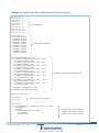
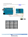
4. Control the module in Serial mode
Circuit below shows how to connect the module to Arduino UNO R3 (EADN014) using 3 signals: TX,
RX and BUSY.
PH_L
+5V
GND
PH_R
(D5) BUSY
TX(D4)>>RX
RX(D3)<<TX
จากภาพจะเห็นได้ว่า มีบอร์ด Arduino UNO R3 (EADN014) ต่อกับโมดูล MP3 ดังนี้
MP3 module
+5V
GND
TX
RX
BUSY
VOL+
VOLHP_L
HP_R
Venus Supply Co., Ltd.
Pin
+5V
GND
D4
D3
D5
Left
Right
Device
Arduino
Arduino
Arduino
Arduino
Arduino
Switch 1
Switch 2
Audio Jack
Audio Jack
Page 13
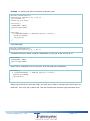
In this example, a software serial is used by setting D3 to be RX and D4 to be TX. The
communication is configured to:
Baud rate: 9600, Data Bit : 8, Stop Bit :1, Parity : None
Commands are exactly the same as used in parallel mode:
Command word
HEX
DEC
0x01
001
0x02
002
…
…..
0xC7
199
0xC8
200
0xC9
201
…
…..
0xE7
231
0xE8
232
0xE9
233
0xEB
235
0xEC
236
0xEF
239
0xF1
241
0xF2
242
…
…..
0xFF
255
Venus Supply Co., Ltd.
Function
Play the first file
Play the second file
….
Play the 199th file
Set volume level to 0 (the lowest level)
Set volume level to 1
….
Set volume level to 31 (the highest level)
Increase volume by 1 level
Decrease volume by 1 level
Pause playback
Resume playback
Stop playback
Change directory to 01 (Root directory)
Change directory to 02
….
Change directory to 15
Page 14
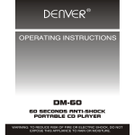
Example 1 In serial mode, send a command to play 001.mp3.
#include <SoftwareSerial.h>
SoftwareSerial mySerial(3, 4); // RX, TX
const int BUSY = 5;
boolean cmd_stop =false;
void setup() {
pinMode(BUSY, INPUT);
mySerial.begin(9600);
}
void loop() {
if ((digitalRead(BUSY) == HIGH) && (cmd_stop == false)) {
Serial.write(0x01);
cmd_stop=true;
}
}
Code description:
#include <SoftwareSerial.h>
SoftwareSerial mySerial(3, 4); // RX, TX
A software serial port named mySerial is established by using D3 as RX and D4 as TX.
void setup() {
pinMode(BUSY, INPUT);
mySerial.begin(9600);
}
BUSY (D5) is configured to be an input port. Then the serial port is initialized.
void loop() {
if ((digitalRead(BUSY) == HIGH) && (cmd_stop == false)) {
mySerial.write(0x01);
cmd_stop=true;
}
}
ในฟงั ก์ชนั ่ void loop ถ้าขาสัญญาณ D5 เป็น “High” และตัวแปร cmd_stop เป็น False โปรแกรมจะส่ง
When logic on BUSY pin becomes “High” and cmd_stop is false, a command 0x01 will be sent via
serial port. Then cmd_stop is set to true. This will command the module to play the first file once.
Venus Supply Co., Ltd.
Page 15
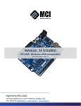
Example 2 In serial mode, send a command to play 002.mp3 in folder 03.
#include <SoftwareSerial.h>
SoftwareSerial mySerial(3, 4); // RX, TX
const int BUSY = 5;
boolean cmd_stop =false ;
void setup() {
pinMode(BUSY, INPUT);
mySerial.begin(9600);
}
void loop() {
if ((digitalRead(BUSY) == HIGH) && (cmd_stop == false)) {
mySerial.write(0xF3);
delay(200);
while(digitalRead(BUSY) == HIGH) {
mySerial.write (0x02);
cmd_stop=true;
}
}
}
Code description:
void loop() {
if ((digitalRead(BUSY) == HIGH) && (cmd_stop == false)) {
mySerial.write(0xF3);
delay(200);
while(digitalRead(BUSY) == HIGH) {
mySerial.write (0x02);
cmd_stop=true;
}
}
}
In loop, when D5 (BUSY) becomes “High” and cmd_stop is false, a command 0xF3 will be sent via
serial port. This will change directory to 03. Then wait until BUSY becomes “High” again and a
command 0x02 is sent to play 002.mp3.
Venus Supply Co., Ltd.
Page 16