1
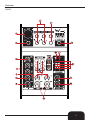
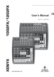
Order Code: MIXE10 - DMIX5
MIXE11 - DMIX6
MIXE12 - DMIX10FX
MIXE10 - DMIX12FX
ENGLISH
WARNING
FOR YOUR OWN SAFETY, PLEASE READ THIS USER MANUAL CAREFULLY
BEFORE YOUR INITIAL START-UP!
CAUTION!
Keep this equipment away from rain,
moisture and liquids.
SAFETY INSTRUCTIONS
Every person involved with the installation, operation & maintenance of this
equipment should:
-
Be competent
-
Follow the instructions of this manual
CAUTION! TAKE CARE USING THIS EQUIPMENT!
HIGH VOLTAGE-RISK OF ELECTRIC SHOCK!!
Before your initial start-up, please make sure that there is no damage caused during
transportation. Should there be any, consult your dealer and do not use the
equipment.
To maintain the equipment in good working condition and to ensure safe operation, it is necessary
for the user to follow the safety instructions and warning notes written in this manual.
Please note that damages caused by user modifications to this equipment are not
subject to warranty.
2
IMPORTANT:
The manufacturer will not accept liability for any resulting damages caused
by the non-observance of this manual or any unauthorised modification to the
equipment.
• Never let the power-cable come into contact with other cables. Handle the power-cable
and all mains voltage connections with particular caution!
• Never remove warning or informative labels from the equipment.
• Do not open the equipment and do not modify the equipment.
• Do not switch the equipment on and off in short intervals, as this will reduce the
system’s life.
• Only use the equipment indoors.
• Do not expose to flammable sources, liquids or gases.
• Do not carry the unit with only one handle. Always carry using both handles.
• Always disconnect the power from the mains when equipment is not in use or before
cleaning! Only handle the power-cable by the plug. Never pull out the plug by pulling the
power-cable.
• Make sure that the available voltage is between 220v/240v.
• Make sure that the power-cable is never crimped or damaged. Check the equipment and
the power-cable periodically.
• If the equipment is dropped or damaged, disconnect the mains power supply immediately.
Have a qualified engineer inspect the equipment before operating again.
• If the equipment has been exposed to drastic temperature fluctuation (e.g. after
transportation), do not switch it on immediately. The arising condensation might damage
the equipment. Leave the equipment switched off until it has reached room temperature.
• If your product fails to function correctly, discontinue use immediately. Pack the unit
securely (preferably in the original packing material), and return it to your Prolight dealer
for service.
• Only use fuses of same type and rating.
• Repairs, servicing and power connection must only be carried out by a qualified
technician. THIS UNIT CONTAINS NO USER SERVICEABLE PARTS.
• WARRANTY; One year from date of purchase.
OPERATING DETERMINATIONS
If this equipment is operated in any other way, than those described in this manual,
the product may suffer damage and the warranty becomes void.
Incorrect operation may lead to danger e.g.: short-circuit, burns and electric shocks etc.
Do not endanger your own safety and the safety of others!
Incorrect installation or use can cause serious damage to people and property.
3
Introduction:
The DMIX5, DMIX6, DMIX10FX and DMIX12FX mixing consoles offer versatility, audio quality and
reliable performance from the minimal chassis size.
With the microphone preamps including phantom power as an option. Balanced line inputs and a
powerful effects section. The mixing consoles in the DMIX Series are equipped for live and studio
applications. Owing to state-of-the-art circuitry your DMIX console produces a warm, analogue
sound that is unrivalled. The microphone channels feature high-end DMIX Mic Preamps that
compare well with costly outboard preamps in terms of sound quality and dynamics and boast the
following features.
• 130 dB dynamic range for an incredible amount of headroom
• Wide bandwidth ranging from below 10 Hz to over 20 KHz for crystal-clear audio reproduction
• Low-noise and distortion-free circuitry guarantees natural and transparent
signal reproduction
• Perfectly matched to every conceivable microphone with up to 60 dB gain and +48 volt
phantom power supply
The equalisers used for the DMIX Series are based on the legendary circuitry of high-end consoles designed in Britain, which are renowned throughout the world for their warm and musical
sound. Even with extreme gain settings these equalisers ensure outstanding audio quality.
EFFECTS PROCESSOR (DMIX10FX and DMIX12FX)
Additionally, your DMIX mixing console has an effect processor with 24-bit A/D converters included, which give your 100 presets producing reverb, delay and modulation effects plus numerous
multi-effects in excellent audio quality
4
Overview:
DMIX5:
5
Overview:
DMIX6:
6
Overview:
DMIX10FX:
7
Overview:
DMIX12FX:
8
Identification:
1, MIC
Each mono input channel offers a balanced microphone input via the XLR connector and also
features switchable +48V phantom power supply for condenser microphones. The DMIX preamps
provide undistorted and noise-free gain as is typically known only from large format consoles.
2, LINE IN
Each mono input also features a balanced line input on a 6.35mm Jack connector. Unbalanced
devices (mono jacks) can also be connected to these inputs.
3, TRIM
Use the TRIM control to adjust the input gain. This control should always be turned fully
counterclock wise whenever you connect or disconnect a signal source to one of the inputs.
The scale has 2 different value range: the first value range (+10 to +60 dB) refers to the MIC input
and shows the amplification for the signals fed in there.
The second value range (+10 to -40 dB) refers to the line input and shows its sensitivity.
4, EQ
All mono input channels include a 3-band equaliser (2-band equaliser DMIX5). All bands provide
boost or cut of up to 15 dB. In the central position, the equalizer is inactive.
5, PAN
The PAN control determines the position of channel signal within the stereo image.
6, LEVEL
The LEVEL control determines the level of the channel signal in the main mix
-Attention: Since the FX path for the effect processor is connected post-fader, the LEVEL control
has to be turned up in order to get this channels signal to the effects processor! (EXCEPT DMIX5)
7, CLIP
The CLIP LED´s of the mono channels illuminate when the input signal is driven too high, which
could cause distortion. If this happens, use the TRIM control to reduce the preamp level until the
LED does not light anymore.
8, LINE IN
Each stereo channel has two balanced line level input on 6.35 mm Jack connectors for left and
right channels. If only the connector marked “L”(left) is used, the channel operates in mono.
Stereo channels are designed to handle typical line level signals. Both inputs will also accept
unbalanced connectors.
9, BAL
The Balance control determines the levels of left and right input signals relative to each other before
both signal are then routed to the main stereo mix bus. If a channel is operated in mono via the line
input, the control has the same function as the PAN control used in the mono channels.
10, LEVEL
The LEVEL control determines the level of the channel signal in the main mix.
9
Identification:
11, MAIN OUT
The MAIN OUT connectors are unbalanced mono connectors.
12, CD / TAPE
INPUT
The CD/MP3/TAPE INPUTS are used to bring an external signal source (e.g. CD player, tape deck,
etc.) into the console. They can also be used as a standard stereo line input.
OUTPUT
These Phono connectors are wired parallel with the MAIN OUT. Connect the inputs of a computer
sound card o ra recorder here. The output signal level is setup using the highly accurate MAIN MIX
fader.
13, PHONES
6.35mm stereo jack for headphones.
14, PHONES LEVEL
CONTROL ROOM LEVEL (EXCEPT DMIX5)
Use the PHONES / CONTROL ROOM level to adjust the signal level of the PHONES / CONTROL
ROOM output
15, MAIN MIX LEVEL
Use the MAIN MIX level control to adjust the signal level of the MAIN MIX outputs.
16, PHANTOM POWER
Phantom power is required to operate condenser microphones and is activated using the
PHANTOM POWER switch. (only available for XLR-Mic input)
17, +48V PHANTOM POWER LED
The +48V LED lights up when phantom power is turned on.
• Caution! You must never use unbalanced XLR connectors on the MIC input connectors if you
want to use the phantom power supply. All connections must be balanced using pins 1-1, 2-2 and
3-3 straight wired.
• Please do not connect microphones to the mixer (or the stagebox/wallbox) as long as the phantom
power supply in switched on. Connect the microphones before you switch on the power supply. In
addition, the monitor/PA loudspeakers should be muted before you activate the phantom power
supply. After switching on, wait approx. one minute in order to allow system to stabilise.
18, CD/TAPE TO PHONES
CD/TAPE TO CONTROL ROOM (EXCEPT DMIX5)
Press the CD/TAPE TO PHONES / CONTROL ROOM switch if you want to monitor the 2-track input
via the PHONES OUTPUT and CONTROL ROOM OUTPUT.
19, CD/TAPE TO MIX
Press the CD/TAPE TO MIX switch if you want to monitor the 2-track input via the MIX OUTPUT.
10
Identification:
20, POWER LED
LED lights up when the Mixer is turned on.
21, SIGNAL AND CLIP LED
The 4-segment level indicator displays the signal level. The CLIP LED´s illuminate when the output
signal is driven too high, which could cause distortion. If this happens, use the MAIN LEVEL control
to reduce the main level until the LED does not light anymore.
22, FX
The FX SEND controls of the stereo channels function similar to those of the mono channels.
However, since the FX send buses are both mono, a mono sum is a first taken from the stereo
input before it is sent to the FX bus.
23, FX SEND CONNECTOR
The FX SEND connector outputs the signal you choose from each individual channel using the FX
SEND controls. You can connect this to the input of an external effects device order to process the
FX bus master signal. Once an effects mix is created, the processed signal can then be routed from
the effects devices outputs back into a STEREO LINE INPUT or the STEREO AUX RETURN (only
DMIX6).
24, STEREO AUX RETURN (ONLY DMIX6)
The STEREO AUX RETURN connectors are used to bring the output of the external effects device
(whose input is derived from the aux sends) back into the console. You can instead use these
connectors as additional inputs, but any effects device will then have to be brought back into the
console via a normal stereo channel. This does, however, give you the ability to use the channel
EQ on the effects return signal if you wish.
-When you are using a stereo channel as effects return path, the FX control of the relevant channel
should generally be turned fully down to avoid undesirable feedback.
25, STEREO AUX RETURN CONTROL (ONLY DMIX6)
Use the AUX RETURN control to determine how much of the effects signal is sent to the main mix.
If only the left connector is used, the AUX RETURN automatically operates in mono.
26, CONTROL ROOM OUT
The unbalanced CTRL ROOM OUT connector carry the summed effects and main mix signals.
The PHONE/CONTROL ROOM control adjusts the level of both headphones and CONTROL
ROOM OUTPUTS.
27, FX TO CTRL
If you want to monitor only the FX send signal in your headphones or monitor speaker(s), press the
FX TO CONTROL ROOM switch.
28, LOW CUT
In addition, the mono channels are equipped with a steep LOW CUT filter designed to eliminate
unwanted low frequency signal components. These can be noise created by hand-held
microphones, subsonic noise or plosive sounds created by highly sensitive microphones.
11
Identification:
29, SENSITIVITY +4 / -10
The stereo inputs have an input sensitivity switch which selects between +4 dBu and -10 dBu.
At -10 dBu (home-recording level), the input is more sensitive (requires less level to drive it) than
at +4 dBu (studio level).
30, FX TO MAIN
The FX TO MAIN control feeds the effects signal into the main mix.
31, PROGRAM
The PROGRAM control has two functions: by turning the PROGRAM control, you choose the
number of an effect. The number of the preset you just chose up blinks in the display. To confirm
your selection, press the PROGRAM control and the blinking stops.
32, DISPLAY
The display shows the effect program number and contains a signal and clip LED. The SIGNAL LED
on the effects module shows the presence of a signal whose level is high enough. This LED should
always be on. However, make sure that the CLIP LED lights up only sporadically. If it is on
constantly, you are overdriving the effects processor, which leads to unpleasant distortion.
If this occurs, turn the FX SEND control down a bit.
12
Rear Panels:
DMIX5:
DMIX6:
DMIX10FX:
DMIX12FX:
AC POWER IN
Connect the power supply to the 3-pin 16.8V AC x 2 connector on the rear of the console. Use the
240V AC adapter supplied to connect the console to the mains. The adapter complies with all applicable safety standards.
• Please use only the power supply unit provided with the console.
• Never connect the DMIX console to the power supply unit while the power supply unit is connected
to the mains! Always connect the console to the power supply unit, then connect the power supply
unit to the mains.
13
Effect Presets:
EFFECTS PRESETS
No.
EFFECT
Description
No.
EFFECT
HALL 00-09
Description
DELAY 50-59
00
SMALL HALL 1
approx. 1.0s reverb decay
50
SHORT DELAY 1
Like a short shattering
01
SMALL HALL 2
approx. 1.2s reverb decay
51
SHORT DELAY 2
1-2 short impulse(s)
02
SMALL HALL 3
approx. 1.5s reverb decay
52
SHORT DELAY 3
1-2 short impulse(s)
03
MID HALL 1
approx. 1.8s reverb decay
53
MID DELAY 1
Classical Delay for up-temp music (115-125 BPM)
04
MID HALL 2
approx. 2.0s reverb decay
54
MID DELAY 2
Classical Delay for mid-temp music (105-115 BPM)
05
MID HALL 3
approx. 2.5s reverb decay
55
MID DELAY 3
Classical Delay for slow-temp music (95-105 BPM)
06
BIG HALL 1
approx. 2.8s reverb decay
56
LONG DELAY 1
Classical Delay for raggae-temp music (85-95 BPM)
07
BIG HALL 2
approx. 3.2s reverb decay
57
LONG DELAY 2
Classical Delay for dub-temp music (75-85 BPM)
08
BIG HALL 3
approx. 4s reverb decay
58
LONG DELAY 3
Extra long (near infinate) delay effect
09
CHURCH
approx. 7s reverb decay
59
LONG ECHO
Extra long canyon echo effect
ROOM 10-19
CHORUS 60-69
10
SMALL ROOM 1
approx. 0.5s reverb decay
60
SOFT CHORUS 1
Unobtrusive effect
11
SMALL ROOM 2
approx. 0.8s reverb decay
61
SOFT CHORUS 2
Unobtrusive effect with different colour
12
SMALL ROOM 3
approx. 1.0s reverb decay
62
WARM CHORUS 1
Analogue sounding
13
MEDIUM ROOM 1
approx. 1.2s reverb decay
63
WARM CHORUS 2
Analogue sounding with different colour
14
MEDIUM ROOM 2
approx. 1.5s reverb decay
64
PHAT CHORUS 1
Pronounced chorus effect
15
MEDIUM ROOM 3
approx. 1.8s reverb decay
65
PHAT CHORUS 2
Pronounced chorus effect with different colour
16
BIG ROOM 1
approx. 2.0s reverb decay
66
CLASSIC FLANGER
Standard flanger effect
17
BIG ROOM 2
approx. 2.2s reverb decay
67
WARM FLANGER
More analogue touch
18
BIG ROOM 3
approx. 2.5s reverb decay
68
DEEP FLANGER
Deep modulation impression
19
CHAPEL
approx. 3s reverb decay
69
HEAVY FLANGER
PLATE 20-29
Extremely pronounced effect
PHASE / PITCH 70-79
20
SHORT PLATE
approx. 1.0s reverb decay
70
CLASSIC PHASER
Standard phaser effect
21
MID PLATE
approx. 1.5s reverb decay
71
WARM PHASER
More analogue touch
22
LONG PLATE
approx. 2.2s reverb decay
72
DEEP PHASER
Deep modulation impression
23
VOCAL PLATE
approx. 1.2s reverb decay
73
HEAVY PHASER
Extreme strong effect
24
DRUMS PLATE
approx. 1.0s reverb decay
74
PITCH SHIFT DETUNE
2-3 times detune for a wider solo voice sound
25
GOLD PLATE 1
approx. 1.2s reverb decay
75
PITCH SHIFT +3
Minor third added voice
26
GOLD PLATE 2
approx. 2.0s reverb decay
76
PITCH SHIFT +4
Minor third added voice
27
SHORT SPRING
approx. 1.0s reverb decay
77
PITCH SHIFT +7
Quint above the added voice
28
MID SPRING
approx. 2.0s reverb decay
78
PITCH SHIFT -5
Fourth down added voice
29
LONG SPRING
approx. 2.5s reverb decay
79
PITCH SHIFT -12
1 octave down added voice
GATED / REVERSE 30-39
MULTI 80-89
30
GATED REV SHORT
approx. 0.8s gate time
80
CHORUS + REVERB 1
Soft chorus + medium-short reverb
31
GATED REV MID
approx. 1.2s gate time
81
CHORUS + REVERB 2
Deep chorus + medium-long reverb
32
GATED REV LONG
approx. 2.0s gate time
82
FLANGER + REVERB 1
Soft flanger + medium-short reverb
33
GATED REV XXL
approx. 3.0s gate time
83
FLANGER + REVERB 2
Deep flanger + medium-long reverb
34
GATED REV DRUMS 1
approx. 0.8s gate time
84
PHASER + REVERB 1
Soft phaser + medium-short reverb
35
GATED REV DRUMS 2
approx. 1.2s gate time
85
PHASER + REVERB 2
Deep phaser + medium-long reverb
36
REVERSE SHORT
approx. 0.8s gate time
86
PITCH + REVERB 1
Soft voice detuning + medium-short reverb
37
REVERSE MID
approx. 1.2s gate time
87
PITCH + REVERB 2
Fourth above interval + medium-long reverb
38
REVERSE LONG
approx. 2.0s gate time
88
DELAY + REVERB 1
Short delay + medium-short reverb
39
REVERSE XXL
approx. 3.0s gate time
89
DELAY + REVERB 2
Medium-long delay + medium-long reverb
EARLY REFLECTIONS 40-49
MULTI 90-99
40
EARLY REFLECTION 1
Short
90
DELAY + GATED REV
Short delay + medium-long gated reverb
41
EARLY REFLECTION 2
Medium-short
91
DELAY + REVERSE
Medium-short delay + medium long reverse reverb
42
EARLY REFLECTION 3
Medium-long
92
DELAY + CHORUS 1
Short delay + soft chorus
43
EARLY REFLECTION 4
Long
93
DELAY + CHORUS 2
Medium-long delay + deep chorus
44
SHORT AMBIENCE
Short
94
DELAY + FLANGER 1
Short delay + soft chorus
45
MID AMBIENCE
Medium-short
95
DELAY + FLANGER 2
Medium-long delay + deep chorus
46
LIVE AMBIENCE
Medium-Short
96
DELAY + PHASER 1
Short delay + soft phaser
47
BIG AMBIENCE
Medium-long
97
DELAY + PHASER 2
Medium-long delay + deep phaser
48
STADIUM
Long
98
DELAY + PITCH 1
Short delay + forth down interval
49
GHOST AMBULANCE
Extra-long special FX
99
DELAY + PITCH 2
Medium-long delay + minor third above interval
14
Specifications:
Model Name:
DMIX5
DMIX6
Channels:
5
6
Mono Mic and Line Input Channels:
1
2
Mono Mic and Line Input Connectors:
XLR, Jack 6.35mm
XLR, Jack 6.35mm
Stereo Line Input Channels:
2
2
Stereo Line Input Connectors:
Jack 6.35mm mono
Jack 6.35mm mono
AUX / Effects Send Channels:
N/A
1
AUX / Effects Send Connectors:
N/A
Jack 6.35mm
Stereo AUX Return:
N/A
1
AUX Return Connectors:
N/A
Jack 6.35mm
Stereo Tape Out:
1
1
Stereo Tape Out Connectors:
Phono
Phono
Stereo Tape In:
1
1
Stereo Tape In Connectors:
Phono
Phono
Stereo Main Out Balanced:
1
1
Stereo Main Out Balanced Connectors:
Jack 6.35mm
Jack 6.35mm
Stereo Control Room Out:
N/A
1
Stereo Control Room Out Connectors:
N/A
Jack 6.35mm
Headphones Out:
1
1
Headphones Out Connectors:
Jack 6.35mm
Jack 6.35mm
Effects Processor:
N/A
N/A
Number of presets:
N/A
N/A
Controls Mono Mic and Line Input Channels: Gain, 2-Band EQ, Pan,
Controls Stereo Line Input Channels:
Gain, 3-Band EQ, FX Send
Channel Volume
Pan, Channel Volume
Balance, Channel Volume
3-Band EQ, FX Send
Balance, Channel Volume
Controls Main Section:
Indicators:
Phones Volume, Master
Phones Volume, Master
Volume, Tape to Phones,
Volume, Tape to Phones,
Tape to Mix,
/Control Room, Tape to Mix
Phantom Power
Phantom Power
Mono Channel Peak, Power, Mono Channel Peak, Stereo,
4 Segment Level Meter,
Power,
Phantom Power
4 Segment Level Meter,
Phantom Power
Power Supply:
External AC adaptor (16.8V) External AC adaptor (16.8V)
Dimensions (W x H x D):
125 x 45 x 195mm
193 x 55 x 240mm
15
Specifications:
Model Name:
DMIX10FX
DMIX12FX
Channels:
10
12
Mono Mic and Line Input Channels:
2
4
Mono Mic and Line Input Connectors:
XLR, Jack 6.35mm
XLR, Jack 6.35mm
Stereo Line Input Channels:
4
4
Stereo Line Input Connectors:
Jack 6.35mm mono
Jack 6.35mm mono
AUX / Effects Send Channels:
1
1
AUX / Effects Send Connectors:
Jack 6.35mm
Jack 6.35mm
Stereo AUX Return:
N/A
N/A
AUX Return Connectors:
N/A
N/A
Stereo Tape Out:
1
1
Stereo Tape Out Connectors:
Phono
Phono
Stereo Tape In:
1
1
Stereo Tape In Connectors:
Phono
Phono
Stereo Main Out Balanced:
1
1
Stereo Main Out Balanced Connectors:
Jack 6.35mm
Jack 6.35mm
Stereo Control Room Out:
1
1
Stereo Control Room Out Connectors:
Jack 6.35mm
Jack 6.35mm
Headphones Out:
1
1
Headphones Out Connectors:
Jack 6.35mm
Jack 6.35mm
Effects Processor:
Yes
Yes
Number of presets:
100
100
Controls Mono Mic and Line Input Channels: Gain, 3-Band EQ, Low Cut
Controls Stereo Line Input Channels:
Controls Main Section:
Gain, 3-Band EQ, Low Cut
(75Hz) FX Send, Pan,
(75Hz) FX Send, Pan,
Channel Volume
Channel Volume
+4 / -10dB switch, FX Send,
+4 / -10dB switch, FX Send,
Balance, Channel Volume
Balance, Channel Volume
Phones Volume, Master
Phones Volume, Master
Volume, Tape to Phones/con- Volume, Tape to Phones/control room, Tape to Mix,
trol room, Tape to Mix,
Phantom Power, FX to CTRL, Phantom Power, FX to CTRL,
Indicators:
FX to Mix
FX to Mix
Mono Channel Peak,
Mono Channel Peak,
Stereo channel Peak, Power, Stereo channel Peak, Power,
4 Segment Level Meter,
4 Segment Level Meter,
Phantom Power, FX number, Phantom Power, FX number,
FX signal, FX clip
FX signal, FX clip
Power Supply:
External AC adaptor (16.8V) External AC adaptor (16.8V)
Dimensions (W x H x D):
217 x 55 x 240mm
269 x 55 x 240mm