1
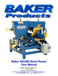
Equipment Photo Baker Corner Rounder User Manual Ellington Industrial Supply, Inc. P. O. Box 128 Ellington, Missouri 63638 USA Web site: www.baker-online.com E-mail: [email protected] Phone: (573) 663 – 7711 Fax: (573) 663 – 2787 TM TABLE OF CONTENTS TAB 1 2 3 4 5 6 7 SECTION AND SUB-SECTION TITLE INTRODUCTION Machine Purpose Machine Function Definition of Terms Manual Contents Notice Machine Specifications and Requirements Warranty Defective Parts Service Policy RULES FOR SAFE OPERATION Safety Expectations for Operating Power Equipment Control of Hazardous Energy – (Lockout / Tagout) Machine Safety Decals INSTALLATION Receiving and Inspection Unpacking Machine Moving Machine Positioning Power and Utilities Requirements SET-UP AND OPERATION Operator Training Initial Start-up Getting Started MAINTENANCE Inspection and Preventative Maintenance Trouble-shooting Chart PARTS AND SERVICE Service Contact Information Serial Number Location ELECTRICAL DIAGRAM Baker Corner Rounder - Rev 1, 12/06; WWW.BAKER-ONLINE.COM 2 PAGE # 3 3 3 4 4 4 5 6 6 7 7 8 9 10 10 10 10 10 10 11 11 11 12 13 13-14 15 16 16 16 17 INTRODUCTION Thank you and congratulations on the purchase of your new Baker Corner Rounder. It has been designed to be durable, productive and easy to use. When properly used and maintained, it will provide you with many years of profitable operation. For safety reasons, and for your own best use of the Baker Corner Rounder, we insist that you read this manual fully, and constantly review and refer back to it as necessary. No one should attempt to operate or perform maintenance on this equipment until they have been trained and taken the time to read and understand the information contained in this manual. Machine Purpose The Baker Corner Rounder is designed to trim or cut the corner of your pallet so that each corner edge is round after being processed on the machine. Corner edge of pallet before being processed Corner edge after processing on the Baker Corner Rounder Machine Function The Baker Corner Rounder utilizes a 10 horsepower electric motor to spin the carbide tip cutter-head and requires incoming air pressure to actuate the cutter-head raise/lower cylinder. The Baker Corner Rounder can cycle approximately 30 times a minute (without material) and process material up to 6 inches in height. Note: The Baker Corner Rounder has a single 6-inch dust removal chute and will not operate without proper dust collection for chip removal. This machine requires a minimum of 1,500 CFM suction at the dust removal chute. Baker Corner Rounder – Rev 1, 12/06; WWW.BAKER-ONLINE.COM 3 Definition of Terms All Stop Safety button (typically “red”) designed to immediately shut-down machine operation CFM (cubic feet per minute) A measure of the volume of a substance flowing through air within a fixed period of time Cutter Head A device that rotates on an axis and cuts wood or other material it is designed to remove Diagram A plan, sketch, drawing, or outline designed to demonstrate or explain how something works or to clarify the relationship between the parts of a whole Fence A straight edge guide used to keep a board a set distance from a blade or cutter Hold-down A device that holds down and steadies the material as it is being cut In-feed The direction a work piece (board) is fed into a blade or cutter Lockout / Tagout The term Lockout/Tagout requires authorized employee(s) to lock and tag the energy-isolating device(s) to prevent the release of hazardous energy in order to prevent injury to employees Off-load The side of a machine where the work piece (board) exits Manual Contents Notice This manual is not totally comprehensive. It does not and cannot convey every possible safety and operational problem that may arise while using this machine. The manual will cover many of the basic and specific safety procedures needed in an industrial environment. All federal and state laws and any regulations having jurisdiction covering the safety requirements for use of this machine take precedence over the statements in this manual. Users of this machine must adhere to such regulations. Machine Specifications and Requirements Cutter: One (1), 10-inch diameter carbide tipped cutter-head Production Rate: Cutter-head cycles approximately 30 times/minute without material Power: 10-hp electric motor Sawdust Removal: 6” (152mm) outlet; min. of 1,500 CFM suction required at machine dust removal chute Required Electrical: 220/440V 3-phase 60Hz (standard USA voltages) Other voltages available upon request, machine comes completely pre-wired; NEMA 12 enclosure with starters, disconnects, control voltage transformer and circuit overload protection; start/stop station with All-stop button Required Air Pressure: Minimum of 3/8-inch incoming airline with a line pressure of at least 120 psi or higher. Set airline regulator to 100 psi. Baker Corner Rounder – Rev 1, 12/06; WWW.BAKER-ONLINE.COM 4 Warranty Ellington Industrial Supply, Inc. machinery is warranted against defects in material or workmanship starting from the date of shipment from the manufacturing plant. This warranty is given solely to the “original purchaser” of the equipment and is in no way to be expressed or implied that it is transferable to any other parties without the written consent and approval from the CEO or Sales Manager of Baker Products. Our one (1) year warranty period covers all items built at our manufacturing facilities including structural frame, cowlings, doors, shafting, dust chutes, belt extenders, conveyor wheels and guards. We honor six (6) months of warranty coverage for miscellaneous vendor-purchasedsupplied items including bearings, chain, sprockets, hydraulic components, etc. Ninety (90) days of warranty coverage is provided on all electrical parts. All electrical components and wiring has been installed in accordance with the National Electrical Code (NEC) of the United States of America. Ellington Industrial Supply, Inc. does not warranty this machine to meet any other requirements or jurisdiction of any electrical or safety codes of any other state, municipality, other country or jurisdiction The purchaser assumes all risk and liability whatsoever resulting from the use thereof whether used singularly or in conjunction with other machinery or apparatus, including, but not limited to, all matters resulting from sawdust generation. Note: No warranty is provided on any electrical components or parts if equipment is powered or connected to a roto-phase electrical converter in order to create a three phase power supply for operational current from a single phase source. Any change in materials, design, or performance intended to improve any product of Ellington Industrial Supply, Inc. shall not obligate Ellington Industrial Supply, Inc. to modify any previously manufactured equipment. This manual may contain details that if not properly followed can affect the performance of your equipment. You are responsible for proper use and maintenance of your equipment and we reserve the right to deny warranty work if deemed to be caused by a lack of proper maintenance or negligence by the owner or any of their employees. Baker Corner Rounder - Rev 1, 12/06; WWW.BAKER-ONLINE.COM 5 Defective Parts Parts claimed defective must be returned freight prepaid, to our plant in Ellington, Missouri. Any part determined defective due to faulty workmanship or materials will be replaced or repaired (at our option) free of charge, F.O.B. our plant. This warranty does not cover expendable items (i.e. drive belts, band wheels, conveyor belting, blades, cutters, guides, etc.). Except as expressly provided herein, this warranty is in lieu of all other warranties, expressed or implied, including a warranty of merchantability or fitness for a particular purpose. This warranty is “void” if any part of the unit has been tampered with, modified, altered, or operated with parts other than supplied or recommended by Ellington Industrial Supply, Inc. In no event shall Ellington Industrial Supply, Inc. be liable for special, indirect, incidental or consequential damages, however arising, including but not limited to, the loss of earnings or the cost of downtime. Service Policy In the event that you have any problems, call us at (573) 663-7711 any time between 8:00 AM and 5:00 PM (CST), Monday through Friday. A member of our trained staff will answer any questions you may have. We charge nothing for this service. The only charge is for replacement parts not covered by warranty or after our inspection we deem that the problem is due to operator error or lack of proper maintenance or neglect. If it is necessary for a member of our service department to visit your plant at your request, there will be a charge for this service. Call our service department for current prices. Retain this Information for your Records Model Number: ……………………………………………………………………. Serial Number: ……………………………………………………………………. Date of Purchase: ………………………………………………………………… Electrical: …………..……………………………………………………………… Dust Removal: ….……………………………………………………………….… Ellington Industrial Supply, Inc. P. O. Box 128 Ellington, Missouri 63638 USA Web site: www.baker-online.com E-mail: [email protected] Phone: (573) 663 – 7711 Fax: (573) 663 – 2787 Baker Corner Rounder - Rev 1, 12/06; WWW.BAKER-ONLINE.COM 6 RULES FOR SAFE OPERATION The purpose of safety symbols and signage is to draw your attention to real or possible hazardous conditions that may exist when operating this equipment. Please remember that safety symbols and signage alone do not eliminate danger and are not substitute for proper training and education regarding operational hazards. This symbol and warning indicates a potentially hazardous situation, which, if not avoided, will result in death or serious injury. This symbol and warning indicates a potentially hazardous situation, which, if not avoided, could result in death or serious injury. This symbol and warning indicates a potentially hazardous situation, which, if not avoided, may result in minor or moderate injury. This warning provides notice and instruction regarding a potentially hazardous situation, which, if not avoided will result in serious injury or death. SAFETY EXPECTATIONS FOR OPERATING POWER EQUIPMENT ALWAYS… • • • • • • • • • • • • ENSURE THAT TRAINED PERSONNEL OPERATE, MAINTAIN AND REPAIR THIS EQUIPMENT TURN POWER OFF AND LOCKOUT / TAGOUT PRIOR TO PERFORMING MAINTENANCE KEEP WORK AREA CLEAN AND WELL LIGHTED TO MINIMIZE OR ELIMINATE HAZARDS KEEP CHILDREN AND VISITIORS AWAY FROM OPERATING EQUIPMENT OPERATE THE EQUIPMENT AT THE RATE IT WAS DESIGNED FOR KEEP GUARDS IN PLACE WHEN OPERATING EQUIPMENT REMOVE TOOLS BEFORE RESUMING OPERATION USE PROPER EXTENSION CORD WEAR PROPER APPAREL AND AVOID CLOTHING AND ACCESSORIES THAT COULD GET CAUGHT IN MOVING PARTS ALWAYS WEAR SAFETY GLASSES AND HEARING PROTECTION AVOID “KICK-BACK” BY KNOWING WHAT CONDITIONS CAN CREATE IT CHECK DAMAGED PARTS AND REPAIR OR REPLACE THEM IMMEDIATELY NEVER… • • • LEAVE TOOL RUNNING OR UNATTENDED, ALWAYS TURN POWER OFF OPERATE EQUIPMENT WHEN TIRED, FATIGUED OR UNDER THE INFLUENCE OF DRUGS OR ALCOHOL ALLOW UNTRAINED PERSONNEL TO OPERATE, MAINTAIN OR REPAIR THIS EQUIPMENT No list of safety expectations can ever be complete as every work environment is as different as the people operating it. Always keep safety as your highest priority and always use this machine with caution and respect. Baker Corner Rounder - Rev 1, 12/06; WWW.BAKER-ONLINE.COM 7 Control of Hazardous Energy – (Lockout / Tagout) Lockout / Tagout (LOTO) refers to specific practices and procedures to safeguard employees from the unexpected energy, startup of machinery/equipment, or the release of hazardous energy during service or maintenance activities. This requires that a designated individual turn off and disconnect the machinery/equipment from its energy source(s) before performing service or maintenance and that the authorized employee(s) lock and tag the energy-isolating device(s) to prevent the release of hazardous energy and take steps to verify that the energy has been isolated effectively. List of Related Terms An employee whose job requires them to operate a machine or piece of Affected equipment on which service or maintenance is being performed under Employee Lockout / Tagout. A person who locks or implements a tagout system procedure on machines Authorized or equipment to perform the service or maintenance on that machine or Employee equipment. An authorized employee and an affected employee may be the same person when the affected employee's duties also include performing service or maintenance. Any source of electrical, mechanical, hydraulic, pneumatic, chemical, Energy thermal, or other energy. Source The placement of a lockout device (such as a lock) on an energy-isolating Lockout device, in accordance with an established procedure that ensures that the energy-isolating device and the equipment being controlled cannot be operated until the lockout device is removed. Workplace activities such as constructing, installing, setting up, adjusting, Servicing inspecting, modifying, and maintaining and/or servicing machines or and / or Maintenance equipment. These activities include lubrication, cleaning or un-jamming of machines or equipment, and making adjustments or tool changes where the employee may be exposed to the unexpected energy, start-up of equipment or release of hazardous energy. The placement of a tagout device on an energy-isolating device, in Tagout accordance with an established procedure, to indicate that the energyisolating device and the equipment being controlled may not be operated until the tagout device is removed. Example of lockout tags, lockout hasp and keyed lock Baker Corner Rounder - Rev 1, 12/06; WWW.BAKER-ONLINE.COM 8 Machine Safety Decals ** Adhere to ALL Safety Warnings! ** Baker Corner Rounder - Rev 1, 12/06; WWW.BAKER-ONLINE.COM 9 INSTALLATION Receiving and Inspection Upon receipt and prior to signing carrier’s documents, conduct a walk-around and visual inspection of your new equipment. Note any damage in writing upon the carrier’s bill of lading and contact us immediately. Note: All new equipment is assembled and thoroughly tested prior to shipment, however damage may occur during transit, which could cause the machine to not operate correctly during start-up. Unpacking If machine was delivered via flatbed trailer, remove straps or chains securing it in place. If machine was delivered by crate, carefully remove upper crating materials from the base skid. Remove lag screws, strapping, etc. that attaches the machine to the skid. Machine Moving Lift machine at the indicated lift points only. o Use a safety strap to avoid tip-over. Transport machine to the installation site. Lift points under the main frame from either side of machine Machine Positioning (Placement, Leveling, Alignment) For optimum performance, designate a solid and level foundation that is covered and dry, free of environmental elements such as rain or snow that could cause electrical or slip hazards. Provide a minimum of 3 feet of clear workspace in front of the electrical panel. Provide a minimum of 4 feet of clear workspace in front of in-feed and off-load area. Power and Utilities Requirements For safe and effective operation confirm your incoming voltage and available amperage is equal to what the machine has been wired for at the factory. ¾ A qualified electrician should complete electrical connections and check for correct motor directional rotation. Ensure all wiring and electrical connections are located in a safe position and away from any hazardous conditions. Efficient dust and chip removal requires a minimum of 1,500 CFM suction at the machine dust removal chute. This is an employer/owner responsibility. Baker Corner Rounder - Rev 1, 12/06; WWW.BAKER-ONLINE.COM 10 SET-UP AND OPERATION Operator Training According to many OSHA, ANSI, STATE, and LOCAL CODES, it is the EMPLOYER’S RESPONSIBILITY to: ¾ Permit only trained and authorized employees to operate and maintain equipment. ¾ Inspect and maintain guards, safety devices and start/stop controls. ¾ Instruct, train and supervise the safe method of work. Be sure personnel are properly trained and safety rules are clearly understood before operating or performing maintenance. 9 9 9 9 9 Operator Machine Guards Devices Instructions All of these together make up the safety system. Failure of any one of these factors will increase accident potential. Initial Start-Up Perform a “bump” to the motor for phase rotation by turning on the power for 1 second. Note: It is recommend you run sufficient test pallets through the machine before making initial corner rounder depth adjustments and after any other adjustments that are made. Note: Prior to start-up and then again after two weeks, check that all nuts and bolts are tight. Then follow the instruction and schedule outlined in the Inspection and Preventative Maintenance section. Baker Corner Rounder - Rev 1, 12/06; WWW.BAKER-ONLINE.COM 11 Getting Started To BEGIN Processing Step 1: Complete a visual inspection to ensure all guards/covers are in place and secure. Step 2: Engage Cutter(s) via control station – press the green “cutter” button(s). Note: Ensure airline is attached and providing ample air pressure to the machine or door/clamp will not open. Step 3: Load pallet onto the in-feed surface and wedge one of the corners into the opening so that it fits firmly against both fences. Step 4: Remove your hands from the pallet and engage both of the black buttons to actuate the door/clamp, holding the pallet in place while the activated cutter-head raises and lowers to round the corner. Step 6: Pull the pallet outward, rotate it to the next corner and repeat Step 4. Continue this sequence until the required number of corners has been rounded. Door/clamp Step 7: Off-load the pallet and re-load the next pallet if opening continuous processing is desired. Control Station Fence In-feed Surface To STOP Processing Step 1: Remove pallet from the in-feed surface and place in a safe location. Step 2: Disengage cutter head by pressing the “All Stop” button. Note: Cutter head does not stop spinning automatically and will coast to a stop. Baker Corner Rounder - Rev 1, 12/06; WWW.BAKER-ONLINE.COM 12 Figure 12 MAINTENANCE Inspection and Preventative Maintenance Note: Prior to start-up and then again after two weeks check that all nuts/bolts and chains are tight, then follow the schedule outlined below from that point forward. Lockout / Tagout power supply prior to inspecting or performing any preventative maintenance. Frequency Daily Weekly Weekly Weekly Monthly Monthly Every 3 Months Recommendation Use an air-hose to remove the wood chips that accumulate in and around the machine. Safely check sharpness carbide cutter-head by inspecting corner round quality; replace as necessary. (Figure 13) Check mainframe and cutter-head drive shaft bearings for wear. Signs of wear include excessive heat, squeaking sounds or looseness. (Figure 13A) Grease cutter-head drive shaft bearings via the grease nipple (Figure 13B). We recommend JT-6 grease (no more than 3 pumps). Grease mainframe bearings (Figure 13A) and raise/lower cylinder shafts (Figure 14) via the grease nipple. We recommend JT-6 grease (no more than 3 pumps). Check drive belt for wear and ensure belt tension is “taut” with no more than ½” deflection (Figure 14A). Grease spherical rod ends (Figure 14B) via the grease nipple. We recommend JT-6 grease (no more than 3 pumps). Weekly Weekly Figure 13A Check mainframe bearings for wear (1 on each corner for a total of 4) – Grease Monthly Weekly Figure 13 Check cutter blades weekly by monitoring corner round quality Figure 13B Check cutter-head drive shaft bearings for wear (1 on each side for a total of 2) – Grease Weekly Baker Corner Rounder - Rev 1, 12/06; WWW.BAKER-ONLINE.COM 13 MAINTENANCE Inspection and Preventative Maintenance Lockout / Tagout power supply prior to inspecting or performing any preventative maintenance. Monthly Monthly No more than ½” deflection in belt tension Figure 14 Figure 14A Grease Raise/lower cylinder shaft via the grease nipples (2 on each shaft pictured, for a total of 4 grease points) Check drive belt for wear and ensure belt tension is “taut” with no more than ½” deflection. Every 3 Months Access spherical rod ends via the side panels Figure 14B Grease spherical rod ends (1 on each end of shaft pictured (2 per side), for a total of 8 collars and grease nipples) Baker Corner Rounder - Rev 1, 12/06; WWW.BAKER-ONLINE.COM 14 Troubleshooting Chart Lockout / Tagout prior to performing any checks or maintenance If Machine won’t start • • • Pallet jams or kick-back occurs • • • • Degrading corner round quality • • • Check Verify incoming voltage and available amperage are equal to what the machine was wired for at the factory. Inspect for loose connection(s). If trouble continues contact our service department or have a qualified electrician trouble-shoot the problem. Verify incoming airline pressure is set at the required psi (100 psi at the regulator) so the door can raise and lower as it’s designed. Check to ensure the airline is not kinked or obstructed in its airflow. Verify that cutter-head can raise and lower without obstruction. Clear machine and re-start operations. Power-down and Lockout / Tagout machine. Safely inspect cutter blades for sharpness; replace as necessary. Check and verify depth of corner round setting. Baker Corner Rounder - Rev 1, 12/06; WWW.BAKER-ONLINE.COM 15 PARTS AND SERVICE Part No. & Pic. Description Part No. & Pic. 101080 Description 101014 BEARING 1” (2-BOLT FLANGE) 17/32” BOLT HOLE BEARING 1-1/4" (2-BOLT FLANGE) 5/8" BOLT HOLE 101125 171096 / 171097 BEARING 1-1/2" PILLOW BLOCK SPHERICAL ROD END (171096 = RIGHT ROD END); (171097 = LEFT ROD END) 241076 111267 TOM THUMB CYLINDER 1-3/8” X 12” BELT B-60 (63”) 241103 151074 ELECTRIC 10-HP MOTOR 208-230/460V ENERTROLS SHOCK 1/2” X 2” W/FIXED SQUARE REAR MOUNT Service Contact Information In the event that you have any problems, call us at (573) 663-7711 any time between 8:00 AM and 5:00 PM (CST), Monday through Friday. Serial Number Location The model and serial number are located on the front right side of the machine. Please refer to your serial number and model number when speaking to a service technician or ordering replacement parts. Baker Corner Rounder - Rev 1, 12/06; WWW.BAKER-ONLINE.COM 16 ELECTRICAL DIAGRAM Baker Corner Rounder - Rev 1, 12/06; WWW.BAKER-ONLINE.COM 17