1
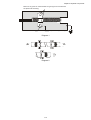
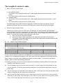
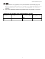
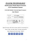
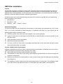
Chapter 07 Optional Components EMI Filter Installation Preface All electrical equipment, including AC motor drives, generates high-frequency/low-frequency noise and interferes with peripheral equipment by radiation or conduction when in normal operation. By using an EMI filter with correct installation, much interference can be eliminated. It is recommended to use DELTA EMI filter to have the best interference elimination performance. We assure that it can comply with following rules when AC motor drive and EMI filter are installed and wired according to user manual: 1. EN61000-6-4 2. EN61800-3: 1996 3. EN55011(1991) Class A Group 1 General precaution To ensure an EMI Filter can maximize its performance on eliminating noise generated by an AC motor drive, it is not only necessary to follow instruction on installation and wiring in a user manual, but the following points need to be kept in mind. . EMI filter and AC motor drive should be installed on the same metal plate Install AC motor drive on the footprint of the EMI filter or install EMI filter as close as possible to the AC motor drive. Wiring should be as short as possible. Metal plate should be grounded. The cover of the AC motor drive or grounding should be fixed on the metal plate and their contact area should be as large as possible. Choose suitable motor & precautions Improper installation and choice of motor cable will affect the performance of EMI filter. Be sure to follow exactly precautions listed below when selecting motor cable. Use a cable with shielding (double shielding is the best). The shielding on both ends of the motor’s cable should be grounded with the minimum length and maximum contact area. Remove any paint on the metal saddle for better ground contact with the metal plate and shielding (See diagram 1). The shielding of motor’s cable should be connected properly to a metal plate. The shielding on both end of the motor’s cable should be fixed on a metal plate by a metal saddle. (See diagram 2) 7-11 Chapter 07 Optional Components Remove any paint on metal saddle for good ground contact with the plate and shielding. saddle the plate with grounding Diagram 1 Diagram 2 7-12 Chapter 07 Optional Components The Length of a motor’s cable 1. Drive in full load of cable length a. Non-shielded cables: The 5.5kW(7.5HP) model and below, max. cable length between the drive and motor is 328ft (100m). The 7.5kW(10HP) model and above is 656ft (200m). b. Shielded cables: The 5.5kW(7.5HP) model and below, max. cable length between the drive and motor is 164ft (50m). The 7.5kW(10HP) model and above is 328ft (100m). The cable length longer than the above suggested, 3-phase load reactor is required. Such as insulation level when there are doubts on the used motor, please refer to the 2nd description 2. Effects of motor insulation class When motor is driven by an AC motor drive of PWM type, the motor terminals will experience surge voltages easily due to components conversion of AC motor drive and cable capacitance. When the motor cable is very long (especially for the 460V series), surge voltages may reduce insulation quality. To prevent this situation, please follow the rules below: a. Use a motor with enhanced insulation b. Connect an output reactor (optional) to the output terminals of the AC motor drive c. The length of the cable between AC motor drive and motor should be as short as possible (10 to 20 m or less) For models 7.5hp/5.5kW and above: Insulation level of motor 1000V 460VAC input voltage 66 ft (20m) 230VAC input voltage 1312 ft (400m) 1300V 328 ft (100m) 1312 ft (400m) 1600V 1312 ft (400m) 1312 ft (400m) For models 5hp/3.7kW and less: Insulation level of motor 1000V 460VAC input voltage 66 ft (20m) 230VAC input voltage 328 ft (100m) 1300V 165 ft (50m) 328 ft (100m) 1600V 165 ft (50m) 328 ft (100m) If motor is driven by an AC motor drive of PWM type, the motor terminals will easily experience surge voltages due to components conversion of AC motor drive and cable capacitance. Especially when the motor's cable is very long, surge voltages may reduce insulation quality. To prevent this situation to happen, please consider the following measures: If the wiring is too long, the amount of stray capacitance between the electrical wires will increase and probably cause leakage of current. Then the display of the current will not be accurate If so, the AC motor drive will activate the over current protection. The worst case caused by leakage of current will be the break down of the AC motor drive. If an AC motor drive is connected to more than one motor, the length of the wiring should be the total length of wiring from the AC motor drive to each motor. When a thermal O/L relay protected by motor is used between AC motor drive and motor, it may malfunction (especially for 460V series), even if the length of motor cable is only 165 ft (50m) or less. To prevent it, please use AC reactor and/or lower the carrier frequency (Pr. 00-17 PWM carrier frequency). 7-13 Chapter 07 Optional Components NOTE When a thermal O/L relay protected by motor is used between AC motor drive and motor, it may malfunction (especially for 460V series), even if the length of motor cable is only 165 ft (50m) or less. To prevent it, please use AC reactor and/or lower the carrier frequency (Pr. 00-17 PWM carrier frequency). Never connect phase lead capacitors or surge absorbers to the output terminals of the AC motor drive. Class, Motor Cable Length & Carrier Frequency Setting for the Filters EMC Standard (IEC 61800-3) Motor Cable length Carrier frequency Built-in filter class C3 non-shielded cable 50m default (8KHz) external DEM filter class C2 shielded cable 50m 15KHz 7-14