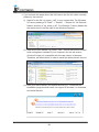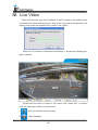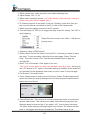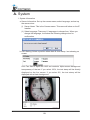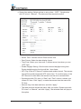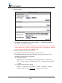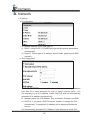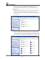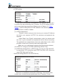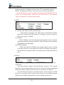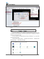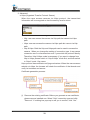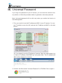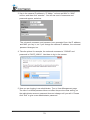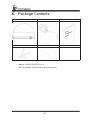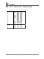
1
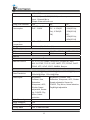
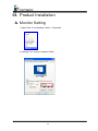
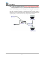
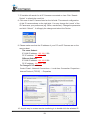
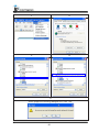
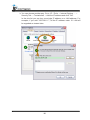
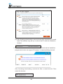
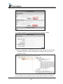
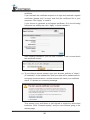
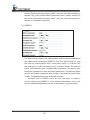
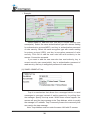
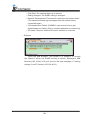
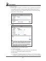
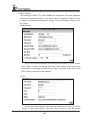
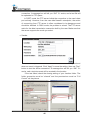
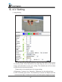
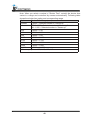
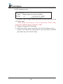
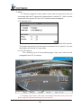
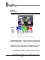
User Manual
INDOOR DOME
IP CAMERA
WARINGS
TO REDUCE THE RISK OF FIRE OR ELECTRIC SHOCK, DO NOT EXPOSE THIS
PRODUCT TO RAIN OR MOISTURE.
DO NOT INSERT ANY METALLIC OBJECT THROUGH VENTILATION GRILLS.
CAUTION
CAUTION
RISK OF ELECTRIC SHOCK
DO NOT OPEN
CAUTION: TO REDUCE THE RISK OF ELECTRIC SHOCK.
DO NOT REMOVE COVER (OR BACK).
NO USER-SERVICEABLE PARTS INSIDE.
REFER SERVICING TO QUALIFIED SERVICE PERSONNEL.
COPYRIGHT
THE TRADEMARKS MENTIONED IN THE MANUAL ARE LEGALLY REGISTERED
TO THEIR RESPECTIVE COMPANIES.
2
CONTENT
III
Preface
4
IIII
Product Specifications
4
IIIII
Product Installation
9
AAA Monitor Setting
9
BBB Hardware Installation
10
CCC IP Assignment
12
DDD Install ActiveX control
14
IIII
Live Video
20
VVV
IP Camera Configuration
22
AAA System
23
BBB Network
27
CCC A/V Setting
47
DDD Event List
54
VVVV Network Configuration
64
VVVVV I/O Configuration
66
VVVVVV Factory Default
69
IIII Universal Password
70
XXX
73
Package Contents
XXXX Micro SD Card Compatibility
74
V1.0_130605
III Preface
This IP Camera is a 1.3 megapixel dome IP camera with the web server built
in. User can view real-time video via IE browser. IP Camera supports simultaneously H.264, Motion JPEG & MPEG4 video compression and dual streaming
which provides smooth and high video quality. The video can be stored in the
SD card and played back remotely. With user friendly interface, it is an easy-touse IP camera which is designed for security application.
IIII Product Specifications
Main Features:
•• 1.3 Mega Indoor IP Camera
•• Support HD 720P Real Time
•• Digital Noise Reduction
•• Digital Wide Dynamic Range
•• Shutter Speed Adjustable
•• Sense Up Adjustable
•• Day&Night Switch Time Control Manfully (Option)
•• Power over Ethernet (Option)
•• H.264/ M-JPEG/ MPEG4 Compression
•• Micro SD Card Backup
•• Support iPhone/Android/Mac
•• SDK for Software Integration
•• Free Bundle 36 ch Recording Software
Fixed Lens Model
PoE Model
IR Model
PoE + IR
Hardware
CPU
RAM
Flash
Image sensor
Sensitivity
Shutter Time
ARM 9 ,32 bit RISC
128MB
16MB
1 / 4” Mega-Pixel CMOS sensor
B / W: 0.5 Lux (AGC Color : 1 Lux (AGC ON)
ON)
B / W: 0.5 Lux (AGC ON)
1 / 10~ 1 / 10,000 sec
Lens Type
4.2mm @ F1.6
Angle of View
52.6° (H), 32.9° (V)
4
I/O
1 DI / 1 DO
Audio
G.711(64K) and G.726(32K,24K) audio compression
Input : External Mic in
Output: External Audio out
Yes
No
Yes
12V DC:2.4W
12V
12V DC:
PoE:2.88W
DC:4.32W(IR
3.24W(IR On);
On); 2.76W(IR
2.76W(IR Off)
Off)
PoE:
4.32W(IR On);
3.36W(IR Off)
0°C ~ 45°C
Power over Ethernet
Max Power
Consumption
Operating
Temperature
Dimensions
IR LEDs (Option)
131.2mm (∅) x 94.3mm (H)
LEDs
IR distance
Network
No
No
28 LEDs, 850nM, 7 LEDs, 850nM,
16M
5M
Ethernet
Network Protocol
10/ 100 Base-T
HTTP, HTTPS, SNMP, QoS/DSCP, Access list, IEEE
802.1X, RTSP, TCP/ IP, UDP, SMTP, FTP, PPPoE, DHCP,
DDNS, NTP, UPnP, 3GPP, SAMBA, Bonjour
System
Video Resolution
Video Adjust
Triple Streaming
Image Snapshot
Full Screen Monitoring
Privacy Mask
1280x1024@20fps, 1280x720@30fps, ,640x480@30fps,
320x240@30fps, 176x144@30fps
Brightness,
Contrast, Hue,
Saturation,
Sharpness, AGC,
Shutter Speed
adjustable, SenseUp, D-WDR, Flip,
Mirror, Noise
reduction
Yes
Yes
Yes
Yes, 3 different areas
5
Brightness, Contrast, Hue,
Saturation, Sharpness, AGC, Shutter
Speed adjustable, Sense-Up,
D-WDR, Flip, Mirror, Noise reduction,
Day&Night adjustable
Compression Format
Video Bitrates Adjust
Motion Detection
Triggered Action
Pre/ Post Alarm
Security
H.264/ M-JPEG/ MPEG4
CBR, VBR
Yes, 3 different areas
Mail, FTP, Save to Micro SD card, SAMBA, DO
Yes, configurable
Password protection, IP address filtering, HTTPS encrypted
data transmission, 802.1X port-based authentication for
network protection, QoS/DSCP
Firmware Upgrade
HTTP mode, can be upgraded remotely
Simultaneous
Up to 10
Connection
Micro SD card management
Recording Trigger
Motion Detection, IP check, Network break down (wire
only),Schedule, DI
Video Format
AVI, JPEG
Video Playback
Yes
Delete Files
Yes
Web browsing requirement
OS
Windows 7, 2000, XP, 2003, Microsoft IE 6.0 or above,
Chrome, Safari, Firefox.
Mobile Support
iOS 4.3 or above, Android 1.6 or above.
Hardware
Suggested
Intel Dual Core 2.53G,RAM: 1024MB, Graphic card: 128MB
Minimum
Intel-C 2.8G, RAM: 512MB, Graphic card: 64MB
Vari-focal Model
PoE Model
IR Model
Hardware
CPU
RAM
Flash
Image sensor
Sensitivity
Shutter Time
ARM 9 ,32 bit RISC
128MB
16MB
1 / 4” Mega-Pixel CMOS sensor
B / W: 0.5 Lux (AGC ON)
Color : 1 Lux (AGC ON)
B / W: 0.5 Lux (AGC ON)
1 / 10 ~ 1 / 10,000 sec
Lens Type
2.8~10mm @ F1.2
Angle of View
25.7°~88.1°(H), 16.1°~54.9°(V)
I/O
1 DI / 1 DO
6
Audio
Power over Ethernet
Max Power Consumption
G.711(64Kbps)/ G.726(24Kbps/32Kbps) audio
compression
Input : External Mic in
Output: External Audio out
Yes
12V DC: 2.4W
PoE: 2.88W
No
12V DC : 4.08W (IR On);
2.52W(IR Off)
Operating Temperature
0°C ~ 45°C
Dimensions
IR LEDs (Option)
131.2mm (∅) x 94.3mm (H)
LEDs
IR distance
Network
No
No
Ethernet
Network Protocol
10/ 100 Base-T
HTTP, HTTPS, SNMP, QoS/DSCP, Access list, IEEE
802.1X, RTSP, TCP/ IP, UDP, SMTP, FTP, PPPoE,
DHCP, DDNS, NTP, UPnP, 3GPP, SAMBA, Bonjour
18 LEDs, 850nM,
12M
System
Video Resolution
Video Adjust
1280x1024@20fps, 1280x720@30fps, ,640x480@30fps,
320x240@30fps, 176x144@30fps
Brightness, Contrast, Hue,
Saturation, Sharpness,
AGC, Shutter Speed
adjustable, Sense-Up,
D-WDR, Flip, Mirror, Noise
reduction
Brightness, Contrast, Hue,
Saturation, Sharpness,
AGC, Shutter Speed
adjustable,
SenseUp, D-WDR, Flip, Mirror,
Noise reduction, Day&Night
adjustable
Triple Streaming
Image Snapshot
Full Screen Monitoring
Privacy Mask
Yes
Yes
Yes
Yes, 3 different areas
Compression Format
Video Bitrates Adjust
Motion Detection
Triggered Action
Pre/ Post Alarm
H.264/ M-JPEG/ MPEG4
CBR, VBR
Yes, 3 different areas
Mail, FTP, Save to Micro SD card, SAMBA, DO
Yes, configurable
7
Security
Password protection, IP address filtering, HTTPS
encrypted data transmission, 802.1X port-based
authentication for network protection, QoS/DSCP
Firmware Upgrade
HTTP mode, can be upgraded remotely
Simultaneous Connection Up to 10
Micro SD card management
Recording Trigger
Motion Detection, IP check, Network break down (wire
only),Schedule, DI
AVI, JPEG
Yes
Yes
Video Format
Video Playback
Delete Files
Web browsing requirement
OS
Windows 7, 2000, XP, 2003, Microsoft IE 6.0 or above,
Chrome, Safari, Firefox.
Mobile Support
iOS 4.3 or above, Android 1.6 or above.
Hardware
Suggested
Minimum
Intel Dual Core 2.53G,RAM: 1024MB, Graphic card:
128MB
Intel-C 2.8G, RAM: 512MB, Graphic card: 64MB
*SPECIFICATIONS ARE SUBJECT TO CHANGE WITHOUT NOTICE.
8
IIIII Product Installation
AAAMonitor Setting
111Right-Click on the desktop. Select “ Properties”
222Change color quality to highest (32bit).
9
BBBHardware Installation
111Camera Construction
Use the screws to lock the bracket to the wall or ceiling, adjust the angle
of lens, and then close the cover.
222Connector Instruction
Connect power adaptor first, then connect the IP Camera to PC or
network, and set up the network configurations according to the network
environment. About I/O setting, please refer to chapter VII in User Manual: "I/
O Configuration" for detail.
10
333PoE ( Power Over Ethernet)(Optional) 802.3af PoE Switch is recommended
Power over Ethernet (PoE) is a technology that integrates power into a
standard LAN infrastructure. It enables power to be provided to the network
device, such as an IP phone or a network camera, using the same cable as
that used for network connection. It eliminates the need for power outlets at
the camera locations and enables easier application of uninterruptible power
supplies (UPS) to ensure 24 hours a day, 7 days a week operation.
11
CCCIP Assignment
111You can use the software“IP Installer” to assign the IP address of IP Camera.
The software is in the attached CD.
222There are two language versions of IP installer. Choose one as your need:
IPInstallerCht.exe: Chinese version
IPInstallerEng.exe: English version
333There are 3 kinds of IP configuration.
aaaFixed IP (Public IP or Virtual IP)
bbbDHCP (Dynamic IP)
cccDial-up (PPPoE)
444Execute IP Installer
555For Windows XP SP2 user, the following message box may pop up. Please
click “Unblock”.
666IP Installer configuration:
12
777IP Installer will search for all IP Cameras connected on Lan. Click “Search
Device” to refresh the result list.
888Click one of the IP Camera listed on the left side. The network configuration
of this IP camera shows on the right side. You may change the “name” of the
IP Camera as your preference (eg: Office, warehouse). Change the parameter
and click “Submit” . It will apply the change and reboot the Device.
999Please make sure that the IP address of your PC and IP Camera are on the
same subnet.
The same Subnet:
IP CAM IP address: 192.168.1.200
PC IP address: 192.168.1.100
Different Subnets:
IP CAM IP address: 192.168.2.200
PC IP address: 192.168.1.100
To Change PC IP address:
Control Panel→Network Connections→ Local Area Connection Properties→
Internet Protocol (TCP/IP) → Properties
1111A quick way to access remote monitoring is to double-click the selected IP
13
Camera listed on “Device list” of IP Installer. An IE browser will be opened.
1111If you link to the IP Camera successgully, there pops a box asking you to log
in. Please key in the default user name"admin" and password"admin" when
you link to the IP Camera for the first time. You can revise the user name and
password later. Please refer to Chapter V: "A.2. User Management".
DDDInstall ActiveX control
111To users of IE 6.0 above
At the first time you access the camera via IE, it will ask you to install the
ActiveX component. If the installation failed, please check the security setting
for the IE browser.
aaaFollow the steps: IE→Tools → Internet Options… → Security Tab →
Custom Level… → Security Settings.
Find the option "Download unsigned ActiveX control"→ Select “Enable” or
Prompt.
Find the option "Initialize and script ActiveX controls not marked as safe" →
Select “Enable” or Prompt.
14
1
2
3
4
5
When popup the following dialogue box, click “Yes”.
15
bbbYou can choose another way. Go to: IE→Tools → Internet Options… →
Security Tab → Trusted sites → Add the IP address and click "OK".
In the site list you can key one single IP address or a LAN address. For
example, if you add "192.168.21.*", all the IP address under .21 LAN will
be regarded as trusted sites.
16
222Use Non-IE Web Browser
If you use firefox or google chrome to access the IP camera but fail to watch
the live video, please follow the steps to install necessary tools:
(the following pictures are based on chrome.)
aaaYou may see the prompt message as the picture below. First, Click the link:
"Firstly, please install Microsoft Visual C++ 2010 Redistributable Package
(x86)."
(((( The link conducts you to the Microsoft official site that you can
download the tools. Please select the language and click "download".
((((( In the pop-up window, please tick the first and the third file as
the picture below. Click "Next" to download both "Microsoft .NET
Framework 4 Client Profile (Web Installer)" and "Microsoft Visual C++
2010 Redistributable Package (x64)".
17
(((((( After fininshing downloading, execute the two files respectively to install
them.The windows may ask you to reboot the PC when the installation
finished.
bbbThen, Click the second link "Please click here to download the installation
program which does not support IE browser." to download Setup ActiveX.
After fininshing downloading, execute the files to install ActiveX. Then
restart the browser.
18
cccIf you execute the steps above but still cannot see the live video normally,
please try the solution:
(((( Search for the file "np_hoem_x.dll" in your system disk. For Windows
XP users, please go to "Start" → "Search" → Search for "All files and
folders" and key in "np_hoem_x.dll". For Windows 7 users, please use
the search bar on the top-right of the Windows Explorer.
((((( Delet all the files named "np_hoem_x.dll". They're the ActiveX control
tools having been installed in your computer, but the old version
of ActiveX might not compatible with the new version of browser.
Therefore, we delete them in order to install the latest ActiveX control.
(((((( Start your web browser, and repeat the step 2-b: "Download the
installation program which does not support IE browser" to download
and install ActiveX.
19
IIII Live Video
Start an IE browser, type the IP address of the IP camera in the address field.
It will show the following dialogue box. Key-in the user name and password. The
default user name and password are “admin” and “admin”.
When the IP Camera is connected successfully, it shows the following program interface.
Double-click the video to switch to full screen view. Press “Esc” or doubleclick the video again back to normal mode.
111
: Get into the administration page
222
: Video Snapshot
20
333Show system time, video resolution, and video refreshing rate
444Adjust image, 1/2x, 1x, 2x
555Select video streaming source (If in”Video Setting” the streaming 2 setting is
closed, this option will not appear here.)
666IP Camera supports 2-way audio. Click the “Chatting” check box, then you
can use microphone connected to the PC to talk to the Camera side.
777Show how many people connect to this IP camera.
888Tick the Relay out "ON" box to trigger the relay output for testing. Tick "Off" to
stop triggering.
Right-Click the mouse on the video, it will show a
pop-up menu.
111Snapshot: Save a JPEG picture
222Record Start: Record the video in the local PC. It will ask you where to save
the video. To stop recording, right-click the mouse again. Select “Record
Stop”. The video format is AVI. Use Microsoft Media Player to play the
recorded file.
333Mute: Turn off the audio. Click again to turn on it.
The "mute" botton does not affect the playback recording video. As long as
the "IP Camera to PC" option in the audio setting is enabled, all the audio will
be recorded into the playback video even you click "mute" in the live page.
444Full Screen: Full-screen mode.
555Zoom: Enable zoom-in and zoom-out functions. Select “Enable digital zoom”
option first within the pop-up dialogue box and then drag and drop the bar to
adjust the zoom factors.
666Frame Buffm Sec: This function is to build a temporary buffm to accumulate
several video frame. This function can make video smooth-going when the
Network speed is slow and lag. If you select “100”, then it plays video after
100 mSec when starting receiving images from camera. The slower the Network is, the bigger value should be selected. The default value is null.
21
VVV IP Camera Configuration
Click
to get into the administration page as below.
Click
to back to the live video page.
22
AAASystem
111System Information
aaaServer Information: Set up the camera name, select language, and set up
the camera time.
(((( Server Name: This is the Camera name. This name will show on the IP
Installer.
((((( Select language: There are 11 languages to choose from. When you
change the language, it will show the following dialogue box for
confirmation.
bbbOSD Setting: Select a position where date & time stamp / text showing on
screen.
Click Text Edit to adjust the OSD text contents. Alpha means background
transparency of the text. If you select 100%, the text stamp will be directly
displayed on the live screen. If you select 0%, the text stamp will be
displayed with a black background.
23
cccServer time setting: Select options to set up time - “NTP”, “Synchronize
with PC’s time”, “Manual”, “The date and time remain the same”.
•• Server Time: It shows current IPCam server time.
•• Date Format: Select the date display format.
•• Time Zone: Select your time zone. It affects server time when you use
“NTP” time.
•• Enable Daylight Saving: Give the start and end daylight saving time.
During daylight saving, the time will be 1 hour faster.
•• NTP: Key in the NTP server IP address and update interval. The camera
time will be synchronized with NTP server time. To use this option, if the
NTP Server is under WAN, the camera must be set to access WAN.
•• Synchronize with PC’s time: In “Date” and “Time” column it shows your
current PC time. Click “Apply” to make the camera time the same with
PC time.
•• Manual: Key in the date and time, and click “Apply”.
•• The date and time remain the same: After you select “Synchronize with
PC’s time” or “Manual”, and click “Apply”, the selected mark will jump to
this option.
24
222User Management
IP CAMERA supports three different users, administrator, general user, and
anonymous user.
aaaAnonymous User Login:
Select “Yes”, then anyone access the camera can watch the live video
without username and password. However, If you try to enter the
configuration page, the camera will ask you to key in the username and
passwork to log in.
Selec "No", then username and password are required to access the
camera.
bbbUniversal Password:
Select “Yes”, then user is allowed to login this IPCam by universal
password. Please refer to “Universal Password” chapter for the function
explanation.
Select “No”, then the universal password function is disabled.
cccAdd user:
Type the user name and password, then click “Add/Set”.The guest user
can only browse the live video page and is not allowed to enter the
configuration page.
dddClick “Edit” or “Remove” in the user list to modify them. The system will ask
you to key in the password in the pop-up window before you edit the user
information.
25
333System update:
aaaTo update the firmware online, click “Browse…” to select the firmware.
Then click “Upgrade” to proceed.
Note: The firmware upgrade might be accompanied by the changing of
some setting and function, and the setting options might become different
to the user manual that you're reading now.
bbbReboot system:re-start the IP camera
cccFactory default:delete all the settings in this IP camera.
dddSetting Management:User may download the current setting to PC, or
upgrade from previous saved setting.
(((( Setting download:
Right-click the mouse button on Setting Download → Select “Save
AS…” to save current IP CAM setting in PC → Select saving directory
→ Save
((((( Upgrade from previous setting:
Browse → search previous setting → open → upgrade → Setting
update confirm → click index.html. to return to main page
26
BBBNetwork
111IP Setting
aaaIP Assignment
IP Camera supports DHCP and static IP.
(((( DHCP: Using DHCP, IP CAMERA will get all the network parameters
automatically.
((((( Static IP: Please type in IP address, subnet mask, gateway, and DNS
manually.
bbbIPv6 Assignment
IPv6 is a newer numbering system that provides a much larger address
pool than IPv4, which accounts for most of today’s Internet traffic. You
can manually key in IPv6 address, enable DHCPv6, and use automatically
generated IPv6 address simultaneously.
(((( Manually setup the IPv6 address: Key in Address, Gateway, and DNS.
((((( DHCPv6: If you have a DHCPv6 server, enable it to assign the IPv6
automatically. The assigned IP address will be displayed beside the
column.
(((((( Automatically generated IPv6 Address: Here indicates a virtual IPv6
27
address generated automatically by IP camera. This virtual IPv6
address cannot use on WAN.
To use IPv6 address to access the IP camera, please open the web
browser, and key in [IPv6 address] in address bar. The [ ] parentheses
mark is necessary.
cccPort assignment
(((( Web Page Port: setup web page connecting port and video transmitting
port (Default: 80)
((((( HTTP Port:setup HTTPS connecting port (Default:443)
dddUPnP (Universal Plug and play)
This IP camera supports UPnP, If this service is enabled on your
computer, the camera will automatically be detected and a new icon will be
added to “My Network Places.”
(((( UPnP Port Forwarding:
When the camera is installed under a router, Enable UPnP Port
Forwarding to let the router open ports so that the video streams can
be sent out from a LAN. Set Web Port, Http Port, and RTSP port, and
make sure your router supports UPnPTM and the function has been
activated.
((((( Note: UPnP must be enabled on your computer. Please follow the
procedure to activate UPnP.
<Approach 1>
•• Open the Control Panel from the Start Menu
•• Select Add/Remove Programs
•• Select Add/Remove Windows Components and open Networking
Services section
•• Click Details and select UPnP to setup the service
28
•• The IP device icon will be added to “MY Network Places”
•• User may double click the IP device icon to access IE browser
<Approach 2>
•• Open "My Network Space", and click "Show icons for networked
UPnP devises" in the tasks column on the left of the page.
Windows may ask your confirmation for enabling the components.
Click "Yes".
•• Now you can see the IP devise under the LAN. Double-click the
icon to access the camera via web browser. To disable the UPnP,
click "Hide icons for networked UPnP devises" in the tasks column.
29
eeeRTSP setting
If you have a media player that supports RTSP protocal, you can use it
to receive the video streaming from IP camera. The RTSP address can be
set for two streamings respectively. Please jump to Chapter V-C:"Video
Setting". There're setting field for RTSP address of two streamings.
(((( RTSP Server: enable or disable
((((( RTSP Authentication:
"Disable" means everyone who knows your camera IP Address
can link to your camera via RTSP. No username and password are
required.
Under "Basic" and "Digest" authentication mode, the camera asks
the user to give username and password before allows accessing.
The password are transmitted as clear text under basic mode, which
provides a lower level of security than under digest mode.
Make sure your media player supports the authenticaton schemes.
(((((( RTSP Port: setup port for RTSP transmitting (Default: 554)
(((((RTSP Start and End Port: in RTSP mode, you may use TCP and UDP
for connecting. TCP connection uses RTSP Port (554). UDP connection
uses RTSP Start and End Port.
fffMulticast Setting (Based on the RTSP Server)
Multicast is a bandwidth conservation technology. This function allow
several user to share the same packet sent from IP camera. To use
30
Multicast, appoint IP Address and port here. TTL means the life time of
packet, The larger the value is, the more user can receive the packet.
To use Multicast, be sure to enable the function "Force Multicast RTP via
RTSP" in your media player. Then key in the RTSP path of your camera:
"rtsp://(IP address)/" to receive the multicast.
gggONVIF
(((( Choose your ONVIF version and settings.
Under ONVIF connection, the video will be transmitted by RTSP.
Be sure to enable the RTSP server in IP setting, or you're not able to
receive the video via ONVIF.
((((( Security:
Select "Disable", then the username and password are not required
when accessing the camera via ONVIF. Select "Enable", then username
and password are necessary.
(((((( RTSP Keepalive:
When the function is enabled, the camera checks once in a while
if the user who links to the camera via ONVIF still keeps connecting. If
the connection had been broken, the camera stop transmitting video to
user.
hhhBonjour
This function enable MAC systems to link to this IP camera. Key in the
name here.
The web browser "Safari" also has Bonjour function. Tick "Include
Bonjour" in the bookmark setting, and you can see the IP camera appearing
under the bonjour category. Click the icon to connect the IP camera.
So far the Bonjour function on Safari browser doesn't support HTTPS
protocol. If you select "https" mode for the camera, you can see the camera
appearing on Safari's bookmarks but cannot access camera via it.
31
iiiLLTD
If your PC supports LLTD, enable this function then you can check the
connection status, properties, and device position(like IP address) of this IP
Camera in the network map.
In the computer running Windows Vista or Windows 7, you can find
LLTD through the path:
Call out the Control Panel → Network and Internet → Network and
Sharing Center → Click "See full map".
32
222Advanced
aaaHttps (Hypertext Transfer Protocol Secure)
When the users access cameras via Https protocol, the transmitted
information will be encrypted so that the security level is arisen.
You can select the connection type.
•• Http: user can access the camera via Http path but cannot via Https
path.
•• Https: user can access the camera via Https path but cannot via Http
path.
•• Http & Https: Both the Http and Https path can be used to access the
camera. When you change the setting of connection type, it may cause
connection error or disconnection error if you switch the protocol directly.
Therefore, Http & Https mode is necessary. If you want to change from
Http to Https, please switch to “Http & Https” mode first, and then switch
to “Https” mode. Vise versa.
Https protocol has certificate verifying mechanism. When the user access a
website via Https, the browser will check the certificate of that domain and
verify its trustiness and secure.
Certificate generation process:
(((( Remove the existing certificate: Before you generate a new certificate,
please remove installed one. Select "Http" connection type and click
"Remove". If a dialog box pops up to ask you to confirm, click “Yes”.
33
((((( Created Request: Fill in the following form and click “apply”.
(((((( After you generate a certificate request, if you choose to turn it to the
trusted third-party to verify, please click “Content” and copy all the
request content.
(((((According to the certificate source, there are two ways to install the
34
certificate.
If you had sent the certificate request to do sign and received a signed
certificate, please click” browse” and find the certificate file in your
computer. Click “Apply” to install it.
If you choose to generate a self-signed certificate, fill in the following
forms and set validity day, click “Apply” to finish installed it.
After finishing installation, you can click “Content” to call out and check
the certificate content.
(((( To use Https to access camera, open your browser, and key in "https://
(IP address)/" in the address bar. Now your data will be transmitted via
encrypted communications, and the browser will check your certificate
status. If it shows you a warning message:
That means your certificate is self-signed or signed by distrusted
institution. Click “Proceed anyway” and you can continue going to the
camera page.
35
bbbSNMP(Simple Network Management Protocol)
SNMP provides a simple framework for administering networked
hardware. To manage the IP camera, you have to prepare a MIB browser
or similar tools first. SNMPv1, SNMPv2c, and SNMPv3 can be enabled
simultaneously.
The following examples are based on MG-SOFT MIB Browser.
Depending on your MIS Browser, you may see different interface and
options. Please refer to the user manual of your MIB Browser.
(((( SNMPv1 and SNMPv2:
The term "Community name" in SNMPv1 and SNMPv2c can be
roughly regarded as key. The person who has the community name has
the authority to read or edit the information of IP camera via SNMP.
Tick the box to enable SNMPv1 or SNMPv2c protocal, and specify
the community name for write(read and write) and read(read-only). The
user who use read community name to access the IP camera cannot
modify any data of this camera. The community name can be any
English characters and numbers, and must be shorter than 31 bits.
•• Example:
Open the MIB Browser. Key in camera IP address(192.168.1.202),
select SNMPv1 or SNMPv2, and key in the community name(Key in the
36
correct Read Community name “public”, the user has read authority to
camera; Key in the correct Read Community name “public” and Key in
the correct Set community name “write”, the user has write authority to
camera.). Connection succeeds.
((((( SNMPv3:
For data security reason, the authentication and encryption assurances
are added when developing SNMPv3. The user has to give not only
the security name(similar with "community name" in v1&v2c) but
the password in order to access the IP camera. Please set security
name, authentication type, authentication password, encryption type,
encryption password of write and read respectively. The security name
can be any English characters and numbers, and must be shorter than
31 bits. The password must be 8~64 bits in length.
Different from in SNMPv1 and v2c, the user have to create a
account when using SNMPv3. In the account parameters, key in the
security name and password you set in the camera to get accessing.
37
•• Example:
Select SNMPv3, add new user, and key in correct security user
name(write). Select the same authentication type with camera setting
for authentication protocol(MD5), and key in authentication password
of write security. Select the same encryption type with camera setting
for privacy protocol (DES), and key in encryption password of write
security. Click OK to add the user who has write authority to the
camera. Connection succeeds.
If you want to add the new user who has read authority, key in
correct security user name(public), key in authentication password of
read security, and key in encryption password of read security.
(((((( SNMPv1/SNMPv2 Trap:
Trap is a mechanism that allows the a managed device to send
messages to manager instead of waiting passively for polling from
the manager. Specify the trap event. When those events happen, the
camera will send the ring message to the Trap Address, which is usually
the manager's IP address. Trap Community means the community that
can receive the trap message.
Note: Trap Address must be under the same LAN with IP camera.
38
•• Cold Start: The camera starts up or reboots.
•• Setting changed: The SNMP setting is changed.
•• Network Disconnected: The network connection was broken down.
(The camera will send trap messages after the network being
connected again)
•• V3 Authentication Failed: A SNMPv3 user account tries to get
authentication but failed. (Due to incorrect password or community)
•• SD Insert / Remove: A Micro SD card is inserted or removed.
•• Example:
Open the MIB Browser. Use SNMPv1 or SNMPv2 to access
the camera. When the SNMP setting is edited, Manager’s MIB
Browser(192.168.40.159) will receive the trap message of “setting
change“ from IP Camera (192.168.40.21).
39
cccAccess List
You can deny an IP address or a range of IP address so that they
cannot access the IP camera. Tick the "enable" box, key in the IP address
you want to deny, select"deny" then click"Add" to add it to the list.
You can also choose to deny a range of IP address but allow one or
several IP address of them. Take the picture above for example, IP address
192.168.50.151~161 are not allowed to connect to the camera, but only
192.168.50.159 can access. Note: In the list "allow" condition must be
ranked before "deny" condition. For example, if we exchange the sequence,
set "Deny: 192.168.50.151~192.168.50.161" for the first item and "Allow:
192.168.50.159" for the second item in the list, the IP "192.168.50.159"
turns out to be denied by the camera because the "deny" condition has the
priority according to our ranking way.
As for those IP addresses not included in the list, the default is “allow”.
40
dddQoS/DSCP(Quality of Server/Differentiated Services Code-point)
DSCP specifies a simple mechanism for classifying and managing
network traffic and provide QoS on IP networks. DSCP is a 6-bit in the IP
header for packet classification purpose.
Set up instruction:
The number 0~63 for Live Stream, Event / Alarm, and Management
represent the ratio that the bandwidth is divided. For example, if you set
5, 10, and 20 for the three items, then the bandwidth of the three item
is 5:10:20. The item getting more bandwidth has lower probability to be
delayed. There is no difference between setting "0, 0, 0" or "63, 63, 63"
because under these two setting the three items will get equal bandwidth
(1/3).
The three stream control the protocols respectively:
•• Live Stream (Video and audio) : RTP / RTSP
•• Event/Alarm : FTP / SMTP / SAMBA / SIP
•• Management : HTTPS / HTTP / SNMP
Note: The "Management" stream handles both the live view and the
setting area of the web page on which the data is transferred via http/https
protocol. If you prefer to distribute more bandwidth when using the web
browser to watch the live video, please adjust the Management Stream
instead of Live Stream.
41
eeeIEEE 802.1x
IEEE 802.1x is an IEEE standard for port-based Network Access
Control. It provides an authentication mechanism to device wishing to
attach to a LAN or WLAN. To use this function, you need a device to build
IEEE 802.1x LAN at first.
The EAPOL protocol support service identification and optional point to
point encryption over the local LAN segment.
Please check what version of the authenticator and authentication
server support. This camera supports EAP-TLS method. Please enter ID,
password issued by the CA, then upload related certificates.
42
333PPPoE & DDNS
aaaPPPoE: Select “Enabled” to use PPPoE. Key-in Username and password
for the ADSL connection. Send mail after dialed: When connect to the
internet, it will send a mail to a specific mail account. For the mail setting,
please refer to Server settings.
bbbDDNS:
It supports DDNS (Dynamic DNS) service.
(((( Enable this service
((((( Key-in the DynDNS server name, user name, and password.
(((((( Set up the IP Schedule update refreshing rate.
(((((Click “Apply”
(((( If setting up IP schedule update too frequently, the IP may be blocked.
In general, schedule update every day (1440 minutes) is recommended
43
(((((DDNS Status
•• Updating: Information update
•• Idle: Stop service
•• DDNS registration successful, can now log by http://<username>.
ddns.camddns.com: Register successfully.
•• Update Failed, the name is already registered: The user name has
already been used. Please change it.
•• Update Failed, please check your internet connection: Network
connection failed.
•• Update Failed, please check the account information you provide:
The server, user name, and password may be wrong.
44
444Server setting
The settings of Email, FTP and SAMBA are used when the event happens,
schedule snapshot executes, or the alarm input is triggered. Select the item
to display the detailed configuration options. You can configure either one or
all of them.
aaaMail Setting:
Set up the server address and account information of your e-mail.
Click “Apply” to save the setting, then use “Test” botton to test the server
connection. A message box will tell you “OK!” if it works, and a test e-mail
will be sent to receiver’s mail address.
bbbFTP:
Set up the server address and account information of your FTP. Click
“Apply” to save the setting, then use “Test” botton to test the server
45
connection. A message box will tell you “OK!” if it works, and a test file will
be uploaded to FTP space.
In PORT mode, the FTP server builds the connection to the user's data
port actively. However, from the user-side firewall's standpoint, the action
of connecting from FTP server is often considered to be dangerous and
should be blocked. In PASV mode, the problem is solved: The FTP server
waits for the data transmission connection built by the user. Make sure that
the server supports the mode you select.
cccSamba:
Select this option to send the media files via a network neighborhood
when an event is triggered. Click “Apply” to save the setting, then use “Test”
botton to test the server connection. A message box will tell you “OK!” if it
works, and a test document will be created in the location.
If the test failed, check the sharing setting of your location folder. The
folder properties must be “shared” and the permissions must be “Full
Control” as the picture.
46
CCCA/V Setting
111Image Setting
For the security and privacy purpose, there are three areas can be setup
for privacy mask. Click Area button first and drag an area on the above
image, and remember to save your setting. The masked area will not show
on both the live view and recording.
Please refer to the details below for Image setting:
aaaBrightness, Contrast, Hue, Saturation, Sharpness can be adjusted here.
bbbAGC: Automatic gain control. The sensitivity of camera can adjusts with the
environmental light. Enable this function and the brighter image can be got
47
under dim light, but the level of noise may also increase.
cccShutter Time: Choose as the location of your camera or fixed shutter time.
The shorter the shutter time is, the less light the camera receives and the
image becomes darker.
dddSense-Up: This function increases the sensitivity of camera to get brighter
image at night. The smaller the value you select, the slower the shutter
speed becomes so that the image will get brighter, and moving subjects
might be blurred.
Sense-Up option is only enabled when users select "outdoor" or "indoor" in
shutter time option.
eeeD-WDR: Digital wide dynamic range. This funtion enables the camera to
reduce the contrast in the view to avoid the dark zones resulting from over
and under exposure.
fffVideo Orientation: Flip or mirror the image as your requirement.
gggDay & Night: The camera can detect the light level of environment. If you
select "Light Sensor Mode", the image will be turned to black and white at
night in order to keep clear. Appoint a lux stantard of switching D/N. The
current lux here is for reference. Under "Times Mode" the switch time of
Color / Black and white is according to the given time. Under "Sychronize
with DI" mode, the image will be turned to black and white when the
camera receives triggering from DI. You can also control it by choosing
"Color" or "B/W".
hhhWhite Balance: Enhance red / blue color in the image.
iiiDNR: Digital noise reduction. This function is able to filter the noise and blur
from the image and show a clearer view. Select the DNR extent.
48
Note: When you select a number in "Shutter Time", actually the shutter time
varies in a range and controlled by camera automatically. Following table
shows the shutter time option and corresponding range.
Option
Outdoor
Indoor
Shutter Time Range (sec.)
1/10000 ~ Selected number in "Sense-up"
NTSC: 1/125 ~ Selected number in "Sense-up"
PAL: 1/100 ~ Selected number in "Sense-up"
1/30
1/10000 ~ 1/30
1/50
1/10000 ~ 1/50
1/60
1/10000 ~ 1/60
1/100
1/10000 ~ 1/100
1/125
1/10000 ~ 1/125
1/250
1/10000 ~ 1/250
1/500
1/10000 ~ 1/500
1/1000
1/10000 ~ 1/1000
* Sense-up options: 1/30, 1/15, 1/10, 1/5
49
222Video Setting
aaaVideo System Setting:
Choose the input resolution, the option affects the max value of video
frame rate.
Choose the Video System, NTSC or PAL.
bbbBasic Mode of Streaming 1 and Streaming 2:
(((( Resolution: If “1280x1024 @20fps” is selected in Input Resolution option, you can select 1280x1024, 640x480, 320x240,or 176x144 here.
If “1280x800 @30fps” is selected in Input Resolution, you can select
1280x800, 1280x720, 640x480, 320x240, or 176x144 here.
((((( Quality: The higher the quality is, the bigger the file size is. It might
affect Internet transmitting speed if the file gets too large.
(((((( Video Frame Rate: The video refreshing rate per second. The max
value is affected by the input resolution you choose.
(((((Video Format: H.264, MPEG4, or M-JPEG
(((( RTSP Path: Set the RTSP output connecting route.
50
cccAdvanced Mode of Streaming 1 and Streaming 2:
(((( Resolution: If “1280x1024 @20fps” is selected in Input Resolution option, you can select 1280x1024, 640x480, 320x240,or 176x144 here.
If “1280x800 @30fps” is selected in Input Resolution, you can select
1280x800, 1280x720, 640x480, 320x240, or 176x144 here.
((((( Bitrate Control Mode: In CBR(Constant Bit Rate) mode, the bitrate
keeps consistent all over the video. In VBR(Variable Bit Rate) mode,
the bitrate changes with the complexity extent of the video data.
VBR provides a better compression way and the file may be smaller.
However, the VBR file size cannot be predicted. The image may
become broken or lagged when your bandwidth is not enough for the
data quantity you selected.
(((((( Video Quantitative: The quality parameter of VBR. You can choose 1~10
compression rate. The higher the value is, the higher the image quality
is.
(((((Video Bitrate: The quality parameter of CBR. You can choose 32kbps
~10Mbps. The higher the value is, the higher the image quality is.
(((( Video Frame Rate: The video refreshing rate per second. The max
value is affected by the input resolution you choose.
(((((GOP Size: It means “Group of Pictures”. The higher the GOP is, the
better the quality is.
((((((Video Format: H.264, MPEG4, or M-JPEG
(((((((RTSP Path: RTSP output connecting route.
51
ddd3GPP Streaming mode:
To receive video via 3gpp, please remember to enable rtsp server in the
"IP Setting" page.
3GPP mode fixed setting: 176x144 resolution, 5FPS, Video
compression: MPEG4, Audio compression: AMR.
(((( Enable or Disable 3GPP Streaming
((((( 3GPP Path: 3GPP output connecting route. If the IP address of your
camera is 192.168.40.150, and you key in "3g" in the column, the 3GPP
path will be rtsp://192.168.40.150/3g.
52
333Audio:
IP Camera supports 2-way audio. Audio can be receive by the mic
connected with the IP camera and transmitted to remote PC. User can also
send audio from remote PC mic to IP Camera’s external speaker.
aaaIP Camera to PC
To receive Audio from IP camera, select “Enable” to start this function.
The Audio compression format can be choosed from 3 options. You can
also adjust the volume of 2-way audio.
bbbPC to IP Camera
Tick “chatting” box in the browsing page, then your voice can be
propagated from PC to camera.
If "Chatting" and "Save to SD card" are enabled simultaneously, the sound
quaily might be affected and becomes not smooth.
53
DDDEvent List
IP Camera provides multiple event settings.
111Event Setting
aaaMotion Detection
To enable motion detection, please tick "Area 1/2/3". Click "Area 1/2/3"
in Area Setting, and draw an area on the preview screen. When motion in
the area is detected, "Motion!" word will be marked on the live screen, and
the camera can send video or snapshot to specific mail addresses, trigger
the output devise, or save video to FTP/ Micro SD card/ Samba.
If you select "save to SD card", the video or sanpshot will be saved to
Micro SD card. If you also tick E-mail/ FTP/ Samba of "Log" option, the
motion detection log will be sent to E-mail/ FTP/ Samba simultaneously.
•• Intervel:
For example, if you select "10 sec" here, once the motion is detected
and action is triggered, it cannot be triggered again within 10 seconds.
•• Based on the schedule:
When the option box is ticked, only during the selected schedule time
the motion detection is enabled. That is, for example, the 11th hour of
54
Monday has not been colored in the schedule table, then no action will
be triggered even the camera detects motion during 11:00~12:00 on
Monday.
bbbTampering Detection
When the camera view is covered, moved, shot by strong light, or out of
focus, the tampering detection will be triggered, and send snapshot or
video to mail/FTP/Samba/SD card, or trigger the external alarm. Please
select the alarm action.
•• Interval: The tampering detecting interval. Take the diagram for example,
we set interval as 30 second, and the camera lens is covered during 1040 sec. At timepoint B, the camera compare the view with timepoint A,
and send alarm when it found that the lens is covered. At timepoint C,
the camera compare the view with timepoint B, and send alarm when it
found that the lens is uncovered.
cccRecord File
When a event happens, the IP camera can record a video clip or take
snapshot, and then send to mail/ FTP/ Samba. Select what format you
want to save.
•• AVI File (with Record Time Setting): Save AVI video file. The video
length is according to the value you set in Record Time Setting.
•• JPEG File (Single File with Interval Setting): Save single JPEG picture
file when event happens.
•• JPEG Files (with Record Time Setting): Only when you select "JPEG" in
55
streaming 1 video format of Video Setting, this option can be enabled.
Select this option to save several JPEG picture files, and the successive
picture files cover a period of time according to the value you set in
Record Time Setting.
dddRecord Time Setting
When a event happens, the IP camera can record a video clip or take
snapshot, and then send to mail/ FTP/ Samba. Select the video recording
length before and after event happens.
•• Diagram example of "Interval" and "Pre/ Post Alarm":
eeeNetwork Dis-connected
To avoid video loss, the camera will start to save the video to local Micro
SD card when it detect Ethernet cable is unplugged. The video recording
will continuously be saved into Micro SD card and divided into every 5
minutes a file until the network is reconnected successfully. The oldest file
will be deleted if the capacity of Micro SD card is full.
This function is only enabled under wire connection.
56
fffNetwork IP check
The same with "Network Dis-connected" function, Network IP chech is
designed for avoiding video loss. Even when the Ethernet cable is plugged,
the network might be sometimes not stable. Key in the target IP address
and interval. The camera checks once in a while according to the setting
interval time that if itself can access the target IP address. If PIN failed, the
camera can start saving the video to Micro SD card. If PIN failed four time
successively, the camera can reboot itself.
57
222Schedule
aaaSchedule: After complete the schedule setup, the camera data will be
recorded according to the schedule setup.
bbbSnapshot: After enable the snapshot function, user can select the storage
position of snapshot file, the interval time of snapshot and the reserved file
name of snapshot.
cccInterval: The interval between two snapshots.
58
333I/O Setting
aaaInput Setting:
IP Camera supports input and output. When the input condition is triggered,
it can trigger the relay out, send the video to mail addresses /FTP server /
SAMBA.
•• Intervel:
For example, if you select "10 sec" here, once the input alarm is
detected and action is triggered, it cannot be triggered again within 10
seconds.
•• Based on the schedule:
When the option box is ticked, only during the selected schedule time
the I/O is enabled. That is, for example, the 11th hour of Monday has
not been colored in the schedule table, then no action will be triggered
even the camera detects input signal during 11:00~12:00 on Monday.
bbbOutput Setting:
The output mode affect the DO or relay out duration.
(((( OnOff Switch: The camera triggers the external devise and lasts for
certain of time according to the event "interval" setting. If it's triggered
by motion detection, the triggering time is according to "interval"
setting of motion detection. If it's triggered by external input alarm, the
triggering time is according to input "interval" setting. It triggers the
external devise and lasts for 10 seconds if you select "10" in interval
setting. You can turn off the alarm manually by click "off" at the right
bottom of the live video page.
((((( Time Switch: The camera triggers the external devise and lasts for
certain of time according to the output "interval" setting, and the user is
not allowed to break off the alarm manually.
59
444Log List
Sort by System Logs, Motion Detection Logs and I/O Logs. In addition,
System Logs and I/O Logs won’t lose data due to power failure.
60
555SD card
aaaPlayback
Please Insert Micro SD card before use it. Make sure pushing Micro SD
card into the slot completely.
Click the date listed on this page, and it shows the list of the video. The
video format is AVI. Click the video to start Microsoft Media Player to play
it. To delete the video, check it, then click "Del".
bbbSD Management
"Auto Deletion” means the recoding files will be deleted after several
days as you selected.
Example: If “The 2st day” is selected, then the recording file at
2012/11/21 5:00AM will be deleted from SD card at 2012/11/23 5:00AM.
That is, if the user check the SD card at 2012/11/21 5:00AM, he can only
find the recording files between 2012/11/19 5:00AM ~ 2012/11/21 5:00AM.
The oldest file will be deleted if the SD card is full.
Note:The use of the SD card will affect the operation of the IP Camera
slightly, such as affecting the frame rate of the video.
61
cccCopy to PC
You can insert the Micro SD card to PC and read the files directly, or use
FlashGet instead to download the files from IP camera. (In this way you do
not need to pull out Micro SD card from the camera.)
To use FlashGet for downloading the image and video data from the
Micro SD card, please follow the steps:
(((( Enter the data list and right-click "Files link daily", select "save target
as..." to save the link list to PC.
((((( Open FlashGet, select "File" → "Import" → "Import list", and find the
link list file you just saved. The file name may be called "SD_list".
(((((( FlashGet will show you the link list, and you can tick the files you
want to copy to your PC. Give the directory path in the new download
window, and remember to enable "Login to Server": key in the IP
Camera username and password.
62
(((((Click OK to start download.
•• FlashGet is a free software that can be downloaded from FlashGet
official website. The example above is based on FlashGet ver.1.9.6.
63
VVVV Network Configuration
•• Configuration 1:
aaaInternet Access: ADSL or Cable Modem
bbbIP address: One real IP or one dynamic IP
cccOnly IP Camera connects to the internet
dddFor fixed real IP, set up the IP into IP Camera. For dynamic IP, start PPPoE.
•• Configuration 2:
aaaInternet AccessL: ADSL or Cable Modem
bbbIP address: More than one real IP or one dynamic IP
cccIP Camera and PC connect to the internet
dddDevice needed: Switch Hub
eeeFor fixed real IP, set up the IP into IP Camera and PC. For dynamic IP, start
PPPoE.
64
•• Configuration 3:
aaa Internet Access: ADSL or Cable Modem
bbbIP address: one real IP or one dynamic IP
cccIP Camera and PC connect to the internet
dddDevice needed: IP sharing
eeeUse virtual IP, set up port forwarding in IP sharing.
65
VVVVVI/O Configuration
111 I/O Connection
aaaPlease connect the GND & DO pin to the external relay (buzzer) device.
bbbPlease connect the GND & DI pin to the external trigger device.
When no event happens, DO output is 5V (DO and GND are disconnected).
When the camera detects event happening and triggers external alarm, DO
output is 0V (DO and GND are connected).
If you select "N.O" in "Input sensor setting", when external devise or circuit
makes DI and GND pin connected, the camera input alarm is triggered,
and then camera will execute the action user has set, for example, send
snapshot to E-mail address.
If you select "N.C" in "Input sensor setting", when external devise or circuit
makes DI and GND pin disconnected, the camera input alarm is triggered,
66
and then camera will execute the action user has set, for example, send
snapshot to E-mail address.
cccI/O PIN definition
•• GND (Ground): Initial state is LOW
•• DO (Digital Output): DC 5V
•• DI (Digital Input): Max. 50mA, DC 5V
222I/O Setup
aaaClick I/O Setting from the system setup page via IE, and check “Out1” to
enable I/O signal.
bbbOutput Test
After the external input and output hardware is installed, you can use the
"Relay Out" bottom on the live video page to test if DO / Relay Out works.
(((( OnOff Switch mode:
Click "ON", the camera will trigger the external output devise. For
example, your alarm buzzer will continuously ring. You can manually
break off the output signal by clicking "OFF".
67
((((( Time Switch mode:
Click "Pulse", the camera will trigger the external output devise
for several seconds, The duration length is according to the "interval"
setting in Output Setting.
68
VVVVVVFactory Default
If you forget your password, please follow the steps to revert back to default value.
•• Remove the power adapter and the ethernet cable. Press and hold the button
in the IP CAMERA.
•• Connect the power to the camera. Don’t release the button during the system
booting.
•• It takes around 30 seconds to boot the camera.
•• Release the button after the camera finishes booting.
•• Plug in the ethernet cable. Re-login the camera using the default IP
(http://192.168.1.200), and user name (admin), password (admin).
69
IIII Universal Password
If you forgot the password of your IP camera, you can reset the camera to factory default, or follow the procedure below to generate a universal password.
Note: Universal password will be valid only when you enable the function in
User Management.
111First, you need to know the IP address and MAC of your IP camera. You can
use IP installer to scan the LAN, and see the IP address and MAC on the side
column.
Or, if you already know the IP address of camera: Open the web browser, key
in “http:// (IP address) /GetIPMAC.cgi” and press enter. The IP address and
MAC will be displayed on browser.
222Find the .html file named “Universal Password” in CD-ROM. Click to open it.
70
333Key in the camera IP address in “IP Adder.” column and MAC in “MAC”
column, and then click “encoder”. You will see a set of username and
password appear, as below:
The universal username and password are generated from the IP address
and MAC you key in, so if you change the camera IP address, the universal
password changes, too.
444Take the picture for example, the universal username is “C90848” and
password is “CNCE_U6KLA”. Use them to log in the camera.
555Now you are logging in as administrator. Turn to User Management page.
The use of universal password does not affect the previous user setting, so
the administrator account password does not change until you edit it. Please
click “Edit” to give a new administrator password.
71
72
XXX Package Contents
IP Camera
Adaptor
Screws x3
CD
•• Adaptor: AC100-240V DC12V/1A
•• The CD includes User manual and software tools.
73
Quick Installation Guide
XXXXXMicro SD Card Compatibility
The following is the Micro SD Card recommended:
Transcend
SanDisk
SDHC
SDHC
SD
SD
SDHC
SDHC
SDHC
SD
SD
SD
SDHC
SDHC
SDHC
SDHC
SDHC
SDHC
SDHC
class4
class4
class4
class4
class6
class6
class6
class6
class6
class6
class10
class10
class10
class4
class4
class4
class4
16GB
32GB
16GB
32GB
4GB
8GB
16GB
4GB
8GB
16GB
4GB
8GB
16GB
4GB
8GB
16GB
32GB
74