1
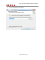
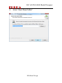
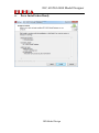
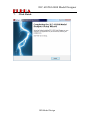
IEC 61850/61400 Model Designer User Manual Part One IED Model Design V 1.5 2015-07 IED Model Design IEC 61850/61400 Model Designer Copyright: All rights reserved. None of the information contained in this document may be reproduced or stored in a database or retrieval system or disclosed to others without written authorization by Fuhua Technologies Co. Ltd. The information in this document is subject to change without prior notice and should not be construed as a commitment by Fuhua Technologies Co. Ltd. Fuhua does not assume responsibility for any errors, which may be in this document. For more information please visit http://iedmodeler.com or contact us at [email protected]. IED Model Design IEC 61850/61400 Model Designer 1. Introduction ........................................................................................................................... 5 2. Installation ............................................................................................................................. 7 2.1 Environment .................................................................................................................... 7 2.2 Install Steps...................................................................................................................... 7 1. Run the Installer by Double Click ............................................................................... 7 2. License Agreement ..................................................................................................... 8 3. Select Destination Location ........................................................................................ 9 4. Select “Start Menu Folder” ...................................................................................... 10 5. Select Additional Tasks ............................................................................................. 11 6. Press Install when Ready .......................................................................................... 12 7. Click Finish ................................................................................................................ 13 3. IED Model Design ................................................................................................................ 14 3.1 Start the Application ...................................................................................................... 15 3.1.1. Run the Application from “Start Menu” ........................................................... 15 3.1.2. Splash Screen .................................................................................................... 15 3.2 The Main GUI Layout ..................................................................................................... 16 3.2.1. Create New Project ........................................................................................... 17 3.2.2. Project Browser ................................................................................................ 18 3.2.3. Find All References ........................................................................................... 19 3.2.4. Element Box ...................................................................................................... 20 3.2.5. Output Windows .............................................................................................. 21 3.2.6. Documentation ................................................................................................. 22 3.2.7. Attribute Box .................................................................................................... 23 3.2.8. Element Editor .................................................................................................. 24 3.2.9. Model Instance ................................................................................................. 25 3.3 System Settings ............................................................................................................. 26 3.4 Create Project ................................................................................................................ 30 3.5 Save Project ................................................................................................................... 32 3.6 Close Project .................................................................................................................. 33 3.7 Open Project .................................................................................................................. 33 3.8 Create SCL ...................................................................................................................... 34 IED Model Design IEC 61850/61400 Model Designer 3.9 SCL Settings.................................................................................................................... 39 3.10 Import SCL ................................................................................................................... 43 3.11 SCL Manipulation ......................................................................................................... 47 3.11.1. Create Element ............................................................................................. 47 3.11.2. Delete Element ............................................................................................. 48 3.11.3. DataTypeTemplates Manipulation ............................................................... 49 3.11.4. IED Manipulation .......................................................................................... 64 3.11.5. Communication Manipulation ...................................................................... 84 3.12 Model Instantiations ................................................................................................... 87 3.15.1. MMS Mapping Model ................................................................................... 87 3.15.2. ACSI General Model ...................................................................................... 88 3.13 Batch Edit Attribute Values ......................................................................................... 88 3.16.1. Export LN/DOI/DAI Attributes ...................................................................... 88 3.16.2. Edit LN/DOI/DAI Attributes with external tool ............................................. 89 3.16.3. Import LN/DOI/DAI Attributes ...................................................................... 90 3.14 Batch Edit Val............................................................................................................... 90 3.15 Export SCL .................................................................................................................... 91 3.18.1. Export Wizard ............................................................................................... 91 3.16 Domain Creation.......................................................................................................... 92 3.17 Project Item Search ..................................................................................................... 95 3.18 Make ICD Template ..................................................................................................... 95 3.19 (Re)instantiate ICD As .................................................................................................. 96 3.20 Forward Model to SCL ................................................................................................. 96 3.21 Reverse Model from SCL ............................................................................................. 97 IED Model Design IEC 61850/61400 Model Designer 1. Introduction The IED Modeler/Designer is a comprehensive IED oriented SCL modelling tool for IEC 61850/61400 and companion standards. It has been designed to keep pace with the evolution of standards. Model Designer, as one of our core products of tool suite is designed to address all the features which are required by different type of users, including IEC 61850 Standard developers, IED vendors, stack vendors, researchers, engineers, utilities companies and people who are interested in applying Model Driven Architecture in system design. With feedbacks from a diversity of users, we keep on developing new features to pill the “pain” confronted when applying IEC 61850/61400 into production. It was born on a mission to help enjoy life in your professional career! The user manual is composed of four parts, but they are independent and not in sequence. Part One: IED Model Design This part is the fundamental. It covers details about installation, introduction to GUI layout, system settings, project management, create/import/modify/export ICD/CID/IID, extract CID from SCD, and generation of TEMPLATE ICD etc. The Intelligent Creation features to save you a lot of time and energy in building error-free IED model, such as customizing data types, creation of LNs of different LNodeTypes, creation of DataSet and Control Blocks, initializing DOI values and configuring Communication parameters etc. All those jobs are very convenient to fulfil with help of user friendly Wizards. In addition it also introduces how to batch edit Attribute Values and Element Values using external tools like Excel; The Search Utilities is designed to be helpful in searching project items. It uses Fuzzy search algorithm, allowing context search of documentation for each Element and Attribute. Part Two: Domain Design This part will introduce you a very comfortable and much higher level of Domain design by utilizing UML technologies. Like other UML tools in the market, Domain design is based on Diagrams. With this tool on hand, you will never feel like asking Domain support from anyone any more. Bet you urgently require Edition 2.0 package for Wind Power, you can home-brew it within one-two hours or even faster if you are an IEC member who is in charge of designing this domain. Within this part Data Type Diagram and Domain Diagram will be introduced, which are much like Class Diagram and Component Diagram in UML, but much more powerful and convenient. Part Three: IED Model Extension This part will introduce how to embed private model information into your SCL without breaking any rules defined by IEC 61850-6. Knowing that SCL is lack of PLC logic equations and internal mappings and many others so on. It also doesn’t address non-IEC 61850 and vendor-specific IED Model Design IEC 61850/61400 Model Designer parameters configuration and that all those information are essential to run an application. To do this, we have to turn to model extension according to IEC 61850-6. Model Designer can give you a cutting-edge, vendor-independent, flexible and programmable way to accomplish that. Part Four: IED Model Validation This part will introduce Schema Check, Integrity Check and Semantic Check against rules defined by Standards. Schema Check is the most popular feature used nowadays and users tend to believe that if Schema Check is passed, their SCL is error-free. But experiences tell us it sounds too good to be true. Why? To fully tell you the reason, I have to write a book about XML Schema defined by W3C. But that is out of the scope of this manual, here I can only tell the reason is because Schema Check are blind to many types of errors in SCL dynamic structures and semantic constraints. Give you one of the most typical example which I guess you are unaware of: <FCDA lnClass="MMXU" fc="MX" daName="PhV.phsA.cVal.mag.i" lnInst="1" ldInst="LDPQ"/> <FCDA lnClass="MMXU" fc="MX" daName="A.phsA.cVal.mag.i" lnInst="1" ldInst="LDPQ"/> The Schema Check is OK about the two DataSet entries above. But they are actually incorrect according to IEC 61850-6. Because PhV.phsA is DO.SDO, not DA. So they should be corrected to <FCDA lnClass="MMXU" fc="MX" doName=" PhV.phsA" daName="cVal.mag.i" lnInst="1" ldInst="LDPQ"/> <FCDA lnClass="MMXU" fc="MX" doName="A.phsA" daName="cVal.mag.i" lnInst="1" ldInst="LDPQ"/> To our surprise is MOST of the stack suppliers “accept” this type of errors. In other words, most of the IEDs in the market are running against the rule defined by IEC 61850-6. This is also the reason why IED Model Validation deserves an independent part of user manual. The good news is that Model Designer offers Integrity Check which can detect errors which are blind to Schema Check. Semantic Check is a feature we will introduce in the future. IED Model Design IEC 61850/61400 Model Designer 2. Installation 2.1 Environment Items Requirement Comment OS XP /Win7/Win8/Higher 32Bit/64Bit Compatible Memory 2G or Above 4G/8G recommended 2.2 Install Steps 1. Run the Installer by Double Click IED Model Design IEC 61850/61400 Model Designer 2. License Agreement IED Model Design IEC 61850/61400 Model Designer 3. Select Destination Location IED Model Design IEC 61850/61400 Model Designer 4. Select “Start Menu Folder” IED Model Design IEC 61850/61400 Model Designer 5. Select Additional Tasks IED Model Design IEC 61850/61400 Model Designer 6. Press Install when Ready IED Model Design IEC 61850/61400 Model Designer 7. Click Finish IED Model Design IEC 61850/61400 Model Designer 3. IED Model Design Domain Domain Domain Design Project Domain Save As Create DataTypeTemplates Create IED Create Communication IED Model Design Validation & Generate Create Header PLC logic equations Management Model Extension Internal Mappings ... IED Model Design is IED oriented and it is supposed to cover all the features required to streamline the processes of IED model development. It can offer you full access (no blind zone) to the manipulation of SCL model. IED Model Design IEC 61850/61400 Model Designer 3.1 Start the Application 3.1.1. Run the Application from “Start Menu” 3.1.2. Splash Screen IED Model Design IEC 61850/61400 Model Designer 3.2 The Main GUI Layout Element Editor Project Brower Model Instance View Attribute Box Documentation Output Windows IED Model Design IEC 61850/61400 Model Designer 3.2.1. Create New Project The project wizard window appears when the application is opened. To avoid this wizard at startup uncheck “Show this dialog at startup”. : Link to our website : Show/hide project description of the current selected template : Create current selected project (or double click the template icon) : Quit the project wizard. IED Model Design IEC 61850/61400 Model Designer 3.2.2. Project Browser Project Browser provides an easy way to manipulate the project tree. A project can contain multiple SCL files (ICD/CID/IID)or domains . Domains are defined in accordance with the IEC 61850/61400 standards; compatible user Domains may be derived from standard domains or created from DataTypeTemplates of an existing SCL. Note: 90% of operations are performed through Project Browser either directly or indirectly. :Create a SCL :Create a domain :Browse or edit namespaces used by current project IED Model Design IEC 61850/61400 Model Designer :Edit Project Settings :Go to Project current item :Collapse all items of project tree :Search project items 3.2.3. Find All References Most IEC 61850-6 SCL Elements are inter-dependent. This means that a change made to one Element may affect others. Find All References helps detect the inter-relationships. Find All References (picture above) enumerates all related Elements in the current active page. The button is used to pinpoint the current enumerated Elements of the current active page. Users can switch to another page to enumerate inter-dependent Elements for other project tree Elements. IED Model Design IEC 61850/61400 Model Designer Element A LNodeType DoType DAType EnumType Inter-dependent A ------ B A ------ B A ------ B A ------ B Element B LN DO SDO DA BDA DA BDA 3.2.4. Element Box Element Box is used to create child Elements of the project tree Elements. The Intelligent Creation feature uses advanced algorithms to protect users from breaking any rules defined in IEC 61850-6. All creatable child nodes of the current selected project tree Element are listed in the box. :Add child Element (or double click the child Element) IED Model Design IEC 61850/61400 Model Designer :Keep track of the latest added element :Go to Project current Element 3.2.5. Output Windows There are four sub-windows in Output Windows; Log: Record messages/operations performed by users XML Schema: SCL Schema check against IEC 61850-6 Model Integrity: Check against errors which cannot be detected by XML Schema check Model Semantic: Check against Semantics defined in IEC 61850 IED Model Design IEC 61850/61400 Model Designer 3.2.6. Documentation Each Element can be documented through Documentation window. Each attribute of an element can also be documented by making use of the Element Editor. The current selected attribute will activate the Documentation window and wait for user to input the documentation details. IED Model Design IEC 61850/61400 Model Designer 3.2.7. Attribute Box Attribute Box is used to add optional attributes to the selected element in the project tree. :Add the selected attribute (or double click the attribute) :Import a group of attributes from Private Namespaces defined in XML Schema file(s) : Show/hide the other data columns IED Model Design IEC 61850/61400 Model Designer 3.2.8. Element Editor Element Editor is a type aware editor. The value fields will create a user friendly value editor to interact with user’s input, preventing errors caused by invalid data. : Delete the selected attribute (or double click the attribute) : Always display the Element Editor : Show/hide the other data columns IED Model Design IEC 61850/61400 Model Designer 3.2.9. Model Instance Each SCL can be instantiated through the Model Instance window. Currently the instantiated model doesn’t include any instances of any Control Blocks/DataSet/Log defined by IEC 61850-6. It ONLY contains Data Instances defined by Data Types of DataTypeTemplates. :Trigger model instantiation :Switch between MMS mapped model instance and IEC61850 ACSI instance (ACSI is more general use case) :To clear Model Instance IED Model Design IEC 61850/61400 Model Designer 3.3 System Settings Choose Edit->Preferences… There are three pages in Preferences dialog: General Page When “Show Warning Before Delete” is checked the tool will ask you for confirmation each time an item is deleted from Project Browser. When “Show Project Wizard on Starting up” is checked the Project Wizard will be displayed automatically at startup. “Find Reference View Count” defines how many pages will be generated when the application is started up (six pages is configured below, readjust count as necessary): IED Model Design IEC 61850/61400 Model Designer When “Enable Specification Dialog” is checked, double clicking on any Project Browser item will trigger a Modeless Specification Dialog; the Element Editor, Attribute Box and Documentation will disappear from the main window automatically. Modeless Specification Dialog is useful for editing multiple elements at the same time. This also makes it possible to integrate extra views to edit/render elements. IED Model Design IEC 61850/61400 Model Designer Directories Page In the Directories page, “Default Working Directory” specifies the default path to store project file while “Default SCL Importation Directory” specifies the default path used to import SCL files. IED Model Design IEC 61850/61400 Model Designer Style Page In the Style page, users can change the GUI appearance to their taste. There are six styles supported. These are cde, default, windows, motif, plastique and cleanlooks. IED Model Design IEC 61850/61400 Model Designer 3.4 Create Project Step One Choose File->New… IED Model Design IEC 61850/61400 Model Designer Step Two From the Wizard, select the Project Template and then double click or press the Create button on the right. For description detail about the selected Project, press Description>> button. Five types of Project Template are provided in the current release. More will follow in future release to follow the evolution of IEC 61850 and its companion standards. Once a Project is created development can proceed i.e. importation of existing SCLs, creation of new SCL etc., No matter what sort of operations are performed the tool will provide assistance to automate the tasks. Now we have a newly created Project named Untitled. IED Model Design IEC 61850/61400 Model Designer 3.5 Save Project Choose File-> Save… and follow the prompted instructions. IED Model Design IEC 61850/61400 Model Designer 3.6 Close Project Choose File ->Close…and follow the prompted instructions. 3.7 Open Project To open an existing Project, one of the two approaches may be used: 1) Choose File-> Open… and follow the prompted instructions. 2) Drag -Drop the Project file on the application main window IED Model Design IEC 61850/61400 Model Designer 3.8 Create SCL Step One Choose Project->Create SCL… or click Create SCL… on the toolbar “Create LNodeTypes Wizard” has five parts: 1) Domain drop box Choose a Domain from which LNodeTypes are to be created. 2) Group drop box of LNodeType Filter out LNodeTypes in accordance to the selected group. 3) Domain tree Enumerate LNodeTypes of the current selected Domain. IED Model Design IEC 61850/61400 Model Designer 4) Object Description Window Display description of the current selected object of Domain tree, such as LNodeType, DO etc. This is useful information to learn about model semantics and get instructions on how to use them. 5) Created LNodeTypes List The newly created LNodeTypes are listed in this window. Step Two From the Domain Tree expand the LNodeType of interest; select and check those DOs needed in the model, and then add the LNodeType using context menu. The Domain Tree is “Extended Selection” enabled: When the user selects a DO in the usual way, the selection is cleared and the new DO selected. IED Model Design IEC 61850/61400 Model Designer However, if the user presses the Ctrl key when clicking on a DO, the clicked DO gets toggled and all other DOs are left untouched. If the user presses the Shift key while clicking on an DO, all items between the current DO and the clicked DO are selected or unselected, depending on the state of the clicked DO. Multiple DOs can be selected by dragging the mouse over them. Step Three For those created LNodeTypes within DataTypeTemplates, the tool will automatically assign them an unique ID (scl:id); the user can change the ID value by double clicking the LNodeType: IED Model Design IEC 61850/61400 Model Designer It is also possible to delete the created LNodeTypes using the context menu: IED Model Design IEC 61850/61400 Model Designer Step Four When everything is ready click Finish to close the wizard. The application will then perform a serial of Element creations which are necessary to a valid SCL, such as Header, Communication, IED as well as their child Elements. IED Model Design IEC 61850/61400 Model Designer 3.9 SCL Settings Before working on the newly created SCL save the project with a key combination of Ctrl + s. SCL Settings are important because they affect how the tool behaves. Use context menu of element scl:SCL and choose SCL Settings… : IED Model Design IEC 61850/61400 Model Designer IED Model Design IEC 61850/61400 Model Designer The SCL Settings dialog will appear: There are two pages (General, Synchronize) in the SCL Settings dialog. General Page There are four settings sections in this page: 1) “SCL Schema for Validation” contains settings for XML Schema validation against SCL Schema as specified in IEC 61860-6. The tool supports two major editions of SCL Schema (edition 1.0 and edition 2.0). By default, the tool uses edition 1.0 to check against SCL model, but users can change it manually to edition 2.0 and choose any other SCL Schema variants available in the system. IED Model Design IEC 61850/61400 Model Designer To use other SCL Schema variants, users need to check “Has Schema” and choose a valid path to the SCL Schema root directory. 2) “SCL Post-Build Event” contains settings for integration with external tools which are qualified to process SCL files. Those external tools are at least able to handle one required input parameter as SCL file name. For example: exterltool.exe <agent.cid> 3) “Manipulate Policies” defines how to process Array Types and DataSets. When Max Array Size is set to zero, it implies that the application will ignore Array Types processing and treat them as an ordinary Data Type (this is the default case for most users). If the value is set greater than ZERO care should be taken as the tool will instantiate all elements of the Array Types in the SCL model. The array size less than 20 is preferred. When Enable Cross-Logical-Device DataSet is set, the tool will allow the user to create DataSets with data entries distributed within multiple Logical Devices of the same IED. It is not receommended to create DataSets in this way but the tool will support the feature. 4) “Namespaces to export” acts as filters. Only those checked Namespaces are allow to export their IED Model Design IEC 61850/61400 Model Designer Elements along with target Namespace. This feature is useful when users have defined Private Namespaces (for more details see other chapters in this manual) for model extension, such as Data Mapping, Logic Definition etc. 3.10 Import SCL SCL importation can be considered as ICD/CID/IID extraction from an SCL file (such as SCD). The importation will ignore Data Types which are unused within the SCL model; in consequence the model will always remain compact, clean and efficient. Choose File-> Import SCL…or click Import SCL on the toolbar. You can also Drag-Drop the SCL file onto the main window to trigger the importation. Step One Load SCL file… IED Model Design IEC 61850/61400 Model Designer If no error messages are reported then proceed to Step Two; Step Two Click Next and select the IED(s) to be imported. IED Model Design IEC 61850/61400 Model Designer Note: Only five SCLs can be created within one project. If you select more than five IEDs, it will ignore the latter ones. Step Three Click Finish and wait for termination. IED Model Design IEC 61850/61400 Model Designer IED Model Design IEC 61850/61400 Model Designer 3.11 SCL Manipulation SCL Manipulation makes use of the tool’s Event Propagation Engine. This event engine is powerful; users don’t have to worry about breaking IEC 61850-6 rules. The tool will propagate the operations that users make and correct any errors introduced. 3.11.1. Create Element Any Element to create is based on context menu or wizard dialog. IED Model Design IEC 61850/61400 Model Designer 3.11.2. Delete Element All Elements are deleted using a context menu. Multiple Elements deletion is supported by “Extended Selection”. IED Model Design IEC 61850/61400 Model Designer 3.11.3. DataTypeTemplates Manipulation An important feature of the tool is Inheritance. All Data Types within Domain or DataTypeTemplates are inheritable. Domain itself can also be inherited. Inheritance can make Data Types creation very easy, because it is possible to reuse those Data already defined in Base Types. Inheritance also makes backward compatibility possible and keeps track of developments in IEC 61850/61400. The picture above is about DataTypeTemplates which inherits Domain IEC61850-7X00-V2.0, IEC61850-7X00-V2.0 which itself is derived from Domain IEC618507X00-V1.0 (A root Domain inherited by any other Domains). Note: If DataTypeTemplates inherits any Domains, a ‘^’ sign will appear alongside. 3.11.3.1. LNodeType Manipulation Create LNodeTypes by Inheritance IED Model Design IEC 61850/61400 Model Designer Fellow the context menu, choose the LNodeTypes from the Dropboxes. Create customized LNodeTypes If all LNodeTypes from standard Domains do not meet user requirements then users can customize compatible LNodeTypes of their own. IED Model Design IEC 61850/61400 Model Designer Edit LNodeTypes Change the LNodeType attributes using Element Editor. Add optional Attributes By default, each newly created Element is only equipped with the required Attributes; optional Attributes should be added manually by users as required. IED Model Design IEC 61850/61400 Model Designer 3.11.3.2. DO Manipulation Create DOs by Inheritance Create customized DOs IED Model Design IEC 61850/61400 Model Designer Add optional Attributes 3.11.3.3. DOType Manipulation Create DOTypes by Inheritance IED Model Design IEC 61850/61400 Model Designer Create customized DOTypes Add optional Attributes IED Model Design IEC 61850/61400 Model Designer 3.11.3.4. SDO Manipulation Create SDOs by Inheritance Create customized SDOs IED Model Design IEC 61850/61400 Model Designer 3.11.3.5. DA Manipulation Create DAs by Inheritance Create customized DAs IED Model Design IEC 61850/61400 Model Designer Create DA default Value From context menu click “Val” Assign Val a default Value. IED Model Design IEC 61850/61400 Model Designer Note: Default values can be very useful when DOI->SDI/DAI->Val is instantiated to have a default value as described by the picture above. 3.11.3.6. DAType Manipulation Create DATypes by Inheritance Create customized DATypes 3.11.3.7. BDA Manipulation Create BDAs by Inheritance IED Model Design IEC 61850/61400 Model Designer Create customized BDAs Create DBA default Value The same as DA. 3.11.3.8. EnumType Manipulation Create EnumTypes by Inheritance IED Model Design IEC 61850/61400 Model Designer Create customized EnumTypes 3.11.3.9. EnumVal Manipulation Create EnumVals by Inheritance Create customized EnumVals IED Model Design IEC 61850/61400 Model Designer 3.11.3.10. Auto Correction Model Integrity Data Types defined within DataTypeTemplates are inter-referenced; any changes made to LNodeType/DOType/DAType/EnumType could affect the Model Integrity if users use Notepad/XML Browser or similar tools to edit SCL files; because those tools are only text-aware, not SCL language aware. A SCL language aware tool should be “intelligent” enough to propagate a chain of change events and execute a series of actions to protect the model from compromising integrity. 3.11.3.10.1. Change Event Auto Correct Data Types Identifiers (scl:id) A value change of scl:id (LNodeType/DOType/DAType/EnumType)can propagate a chain of change events to the affected receivers, for example, CMV is referenced by three SDOs; before scl:id change, CMV looks like this: After scl:id change, CMV looks like this (with auto correction): IED Model Design IEC 61850/61400 Model Designer Users may not be aware of this auto corrections. This propagation applied to the elements listed below: Element Name LNodeType DOType DAType EnumType Propagate Direction -------------- -------------- -------------- -------------- Auto Corrected Elements LN0 LN DO SDO DA BDA DA BDA Name Change Event (scl:name) A value of scl:name(DO/SDO/DA/BDA) can be detected by the tool but no actions are taken right now, but tool provides Model Integrity check to help users pinpoint those errors. 3.11.3.10.2. Deletion Event When any type of LNodeType/DOType/DAType/EnumType is deleted , all the related LN/DO/DA/BDA are no longer valid; the action taken is to delete them from model to protect model integrity. For example, before CMV deletion, it looks like this: IED Model Design IEC 61850/61400 Model Designer After CMV deletion, it looks like this: This propagation applied to the elements listed below: Element Name LNodeType DOType DAType EnumType Propagate Direction -------------- -------------- -------------- -------------- IED Model Design Elements to Delete LN0 LN DO SDO DA BDA DA BDA IEC 61850/61400 Model Designer 3.11.4. IED Manipulation 3.11.4.1. Services Choose the required services from dropbox: 3.11.4.2. AccessPoint Choose Server/LN/ServerAt from the dropbox: IED Model Design IEC 61850/61400 Model Designer 3.11.4.3. LDevice Choose LNodeType from dropbox to create LN0/LN Create LN0 instance: IED Model Design IEC 61850/61400 Model Designer Create LN instances: IED Model Design IEC 61850/61400 Model Designer LN creation is as simple as choosing LNodeType from a prompted dropbox, if you create more than one LNs of the same LNodeType, the tool will automatically increase the Suffix. Users can also clone an existing LN by clicking toolbar button . 3.11.4.3.1. LN0/LN 3.11.4.3.1.1. DataSet 3.11.4.3.1.1.1. Create DataSet Choose DataSet from dropbox. 3.11.4.3.1.1.2. Edit DataSet Introduction to DataSet Editor Choose Edit DataSet…: IED Model Design IEC 61850/61400 Model Designer The DataSet Editor is composed of two parts marked as ① and ② respectively: The left window marked ① is the model instance tree; here the user can browse and navigate to any data entries FCDA. The window on the right marked ② is DataSet entries window. At the top of the window, there are a couple of dropboxes, and several tool buttons. : Filter model instances by LNodeType : Filter model instances by Functional Constraint : Expand/collapse model instance tree down to the levels of LD, LN, FC, DO or DA IED Model Design IEC 61850/61400 Model Designer : Collapse all model instances : Delete the selected entries from the DataSet : Validate the added DataSet entries : Show/hide any other columns information Note: If you intend to add dataset entries from any other Logical Devices of the same IED, please go to System Settings section for more details. Add DataSet Entries DataSet Editor is a comprehensive wizard: IED Model Design IEC 61850/61400 Model Designer Multiple entries selection: DataSet entries filter: IED Model Design IEC 61850/61400 Model Designer Delete DataSet Entries 3.11.4.3.1.2. ReportControl Add ReportControl Block IED Model Design IEC 61850/61400 Model Designer Change Attribute’s Values Presenation Format:Control Block Name >> DataSet Name 3.11.4.3.1.3. LogControl Add LogControl Block IED Model Design IEC 61850/61400 Model Designer Change Attribute’s Values Presentation Format:Control Block Name >> DataSet Name IED Model Design IEC 61850/61400 Model Designer 3.11.4.3.1.4. DOI Add DOI To add DOI select the DOI required from dropbox. The tool will automate the full creation of DOI. The full creation covers all levels of SDI/DAI and Val default value assignment if available from DBA/DA. This type of Intelligent Creation saves time and avoids errors 1. Select the DOI to create 2. Intelligent creation of DOI 3. Selective deletion of SDI/DAI ( , ) IED Model Design IEC 61850/61400 Model Designer 4. After selective deletion of SDI/DAI ( 5. Selective addition of SDI/DAI ( , , ) ) IED Model Design IEC 61850/61400 Model Designer 6. After selective addition of SDI/DAI ( 7. Reposition of SDI/DAI ( , ) ) Note:Repositioning Element is enabled by Drag & Drop operation too. Edit DOI IED Model Design IEC 61850/61400 Model Designer DOI is composed of set of Data Attributes organized in hierarchical structure. In practice it is necessary to configure initial values of Val and some important attributes, such as sAddr, valKind, desc etc. 1. Introduction to Initial Value Editor Choose Edit DOI… from context menu. Overview of Initial Value Editor: IED Model Design IEC 61850/61400 Model Designer There are five columns in the Data Attributes entries list, marked as ①、②、③、④、⑤ respectively. ① : Data Attributes flattened name (Data Object Reference) ② : Data Attributes Value ③ : Data Attributes Basic Type ④ : Functional Constraint (FC) ⑤ : Short address (sAddr) 2. Delete Data Attributes entries By default, DOI creation will create all Data Attributes entries, but in practice only some of them are configured e.g. those with Functional Constraint CF, EX, DC etc. Users should delete those entries that are unnecessary from DOI to avoid making the SCL model much bigger in size. This is IED Model Design IEC 61850/61400 Model Designer especially the case for resource constrained devices (IEDs). 3.11.4.3.1.5. Inputs This version of the tool does not have a feature to facilitate the creation of scl:ExtRef;, users must create these manually and be responsible for their correctness. The picture above defines five External References: : Doesn’t specify what type of service (scl:serviceType) : Service type of Poll : Service type of Report : Service type of GOOSE : Service type of SMV 3.11.4.3.1.6. Log To create a Log is very simple. IED Model Design IEC 61850/61400 Model Designer 3.11.4.3.1.7. GSEControl Create GSEControl Block Change Attributes Values Presentation IED Model Design IEC 61850/61400 Model Designer Format:GSEControl Block name >> DataSet Name 3.11.4.3.1.8. SampledValueControl Create SampledValueControl Block Change Attributes Values IED Model Design IEC 61850/61400 Model Designer Presantation Format:SampledValueControl Block name >> DataSet Name IED Model Design IEC 61850/61400 Model Designer 3.11.4.3.1.9. SetttingControl 3.11.4.3.1.10. Auto Correction Model Integrity 3.11.4.3.1.10.1. FCDA Auto Correction Element Name LD:inst LN:prefix/lnClass/inst Propagate Direction ------------- ------------- Auto Corrected Elements FCDA:ldInst FCDA:prefix/lnClass/lnInst IED Model Design IEC 61850/61400 Model Designer 3.11.4.3.1.10.2. Control Blocks Auto Correction Element Name Propagate Direction Auto Corrected Elements ------------- ------------- DataSet:name ------------- ------------- ReportControl:datSet LogControl:datSet GSEControl:datSet SampledValueControl:datSet 3.11.5. Communication Manipulation 3.11.5.1. SubNetwork Choose SubNetwork to create SubNetwork elements. IED Model Design IEC 61850/61400 Model Designer 3.11.5.2. ConnectedAP Choose ConnectedAP to create ConnectedAP elements. 3.11.5.2.1. Address IED Model Design IEC 61850/61400 Model Designer 3.11.5.2.2. GSE 3.11.5.2.3. SMV IED Model Design IEC 61850/61400 Model Designer 3.12 Model Instantiations There are two types of Model Instantiations supported: MMS Mapping Model, ACSI General Model. 3.15.1. MMS Mapping Model :To create instantiated model :Switch between MMS Mapping and ACSI General IED Model Design IEC 61850/61400 Model Designer 3.15.2. ACSI General Model 3.13 Batch Edit Attribute Values SCL is organized in hierarchical structure. To batch edit Attribute Values, we need to flatten those names into a table and export it to edit by external tools like Excel. 3.16.1. Export LN/DOI/DAI Attributes Export CVS Data Format IED Model Design IEC 61850/61400 Model Designer Select Element and its Attribute to export 3.16.2. Edit LN/DOI/DAI Attributes with external tool Edit it with Excel: IED Model Design IEC 61850/61400 Model Designer 3.16.3. Import LN/DOI/DAI Attributes CVS Format File: 3.14 Batch Edit Val The same as batch edit Attribute Values. IED Model Design IEC 61850/61400 Model Designer 3.15 Export SCL 3.18.1. Export Wizard Trigger Export Basic Settings ① Select which SCL(s) to export ② Specify IEC 61850 edition ( 1.0/2.0) ③ Specify Private Namespaces to export ④ Specify SCL Schema if any ⑤ Specify the output SCL file name IED Model Design IEC 61850/61400 Model Designer Execution 3.16 Domain Creation Users can create compatible Domains of their own. From toolbar click button Select SCL(s) from which Domain(s) are to create IED Model Design IEC 61850/61400 Model Designer Select paths to store Domain(s) Click Finish when Ready IED Model Design IEC 61850/61400 Model Designer After Creation IED Model Design IEC 61850/61400 Model Designer 3.17 Project Item Search The tool provides comprehensive item search facility. 3.18 Make ICD Template IED Model Design IEC 61850/61400 Model Designer 3.19 (Re)instantiate ICD As 3.20 Forward Model to SCL IED Model Design IEC 61850/61400 Model Designer 3.21 Reverse Model from SCL IED Model Design