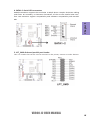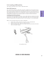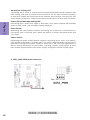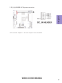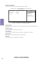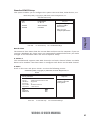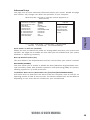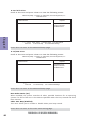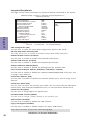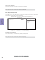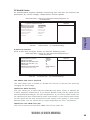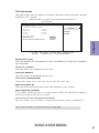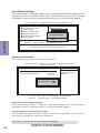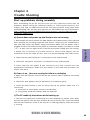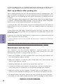
1
Preface Copyright This publication, including all photographs, illustrations and software, is protected under international copyright laws, with all rights reserved. Neither this manual, nor any of the material contained herein, may be reproduced without written consent of the author. Version 1.0 Disclaimer The information in this document is subject to change without notice. The manufacturer makes no representations or warranties with respect to the contents hereof and specifically disclaims any implied warranties of merchantability or fitness for any particular purpose. The manufacturer reserves the right to revise this publication and to make changes from time to time in the content hereof without obligation of the manufacturer to notify any person of such revision or changes. Trademark Recognition Microsoft, Windows and Windows 7/8 are registered trademarks of Microsoft Corp. VIA® are registered trademarks of VIA Corporation. Other product names used in this manual are the properties of their respective owners and are acknowledged. Federal Communications Commission (FCC) This equipment has been tested and found to comply with the limits for a Class B digital device, pursuant to Part 15 of the FCC Rules. These limits are designed to provide reasonable protection against harmful interference in a residential installation. This equipment generates, uses, and can radiate radio frequency energy and, if not installed and used in accordance with the instructions, may cause harmful interference to radio communications. However, there is no guarantee that interference will not occur in a particular installation. If this equipment does cause harmful interference to radio or television reception, which can be determined by turning the equipment off and on, the user is encouraged to try to correct the interference by one or more of the following measures: • • • • Reorient or relocate the receiving antenna Increase the separation between the equipment and the receiver Connect the equipment onto an outlet on a circuit different from that to which the receiver is connected Consult the dealer or an experienced radio/TV technician for help Shielded interconnect cables and a shielded AC power cable must be employed with this equipment to ensure compliance with the pertinent RF emission limits governing this device. Changes or modifications not expressly approved by the system’s manufacturer could void the user’s authority to operate the equipment. VX900-I2 USER MANUAL Declaration of Conformity This device complies with part 15 of the FCC rules. Operation is subject to the following conditions: • This device may not cause harmful interference. This device must accept any interference received, including interference that may cause undesired operation. This device is in conformity with the following EC/EMC directives: Limits and methods of mesurement of radio disturbance char EN 55022 acteristics of information technology equipment EN 61000-3-2 Disturbances in supply systems caused • EN 61000-3-3 Disturbances in supply systems caused by household appliances and similar electrical equipment “ Voltage fluctuations” EN 55024 Information technology equipment-Immunity characteristicsLimits and methods of measurement Safety for information technology equipment including electrical business equipment EN 60950 CE marking Canadian Department of Communications This class B digital apparatus meets all requirements of the Canadian Interferencecausing Equipment Regulations. Cet appareil numérique de la classe B respecte toutes les exigences du Réglement sur le matériel brouilieur du Canada. About the Manual The manual consists of the following: ii Chapter 1 Introducing the Motherboard Describes features of the motherboard. H page 1 Chapter 2 Installing the Motherboard Describes installation of motherboard components. H page 7 Chapter 3 Using BIOS Provides information on using the BIOS Setup Utility. H page 23 Chapter 4 Trouble Shooting Provides basic shooting tips. H page 43 VX900-I2 USER MANUAL trouble TABLE OF CONTENTS Preface i Chapter 1 1 Introducing the Motherboard 1 Introduction...........................................................................................1 Specifications......................................................................................2 Motherboard Components................................................................3 I/O Ports...............................................................................................5 Chapter 2 7 Installing the Motherboard 7 Safety Precautions..............................................................................7 Installing the Motherboard in a Chassis.......................................7 Checking Jumper Settings..................................................................8 Installing Hardware...........................................................................9 Installing Memory Modules.....................................................9 Installing Add-on Cards..........................................................10 Connecting Optional Devices.................................................12 Installing a SATA Hard Drive...................................................17 Connecting Case Components........................................................18 Front Panel Header................................................................19 Chapter 3 23 Using BIOS 23 About the Setup Utility......................................................................23 The Standard Configuration........................ ...........................23 Entering the Setup Utility.......................................................23 Resetting the Default CMOS Values.....................................24 Using BIOS..........................................................................................25 BIOS Navigation Keys..............................................................25 System Information................................................................26 Standard CMOS Setup................................................................27 Advanced Setup......................................................................29 Advanced Chipset Setup.........................................................31 Integrated Peripherals...........................................................32 Power Management Setup.....................................................33 PCI/Plug and Play Setup...........................................................34 PC Health Status....................................................................35 CPU Information....................................................................37 Load Default Settings...........................................................38 VX900-I2 USER MANUAL iii Supervisor Password.............................................................38 User Password......................................................................39 Save & Exit Setup....................................................................40 Exit Without Saving.....................................................................40 Updating the BIOS......................................................................41 Chapter 4 43 Trouble Shooting 43 Start up problems during assembly..............................................43 Start up problems after prolong use............................................44 Maintenance and care tips..............................................................44 Basic Troubleshooting Flowchart.....................................................45 iv VX900-I2 USER MANUAL Introduction Chapter 1 Chapter 1 Introducing the Motherboard Thank you for choosing the VX900-I2 motherboard. This motherboard is a high performance, enhanced function motherboard with onboard VIA® Eden X2 U4200/ VIA® Nano Single Core U3300 Processor. This motherboard is based on VIA® VX900 Express Chipset for best desktop platform solution. It supports up to 8 GB of system memory with single channel DDR3 1066 MHz. It also supports one PCIEX8 slot and one mini PCIE slot. It implements an EHCI compliant interface that provides eight USB 2.0 ports (four USB 2.0 ports and two USB 2.0 headers support additional four USB 2.0 ports). This motherboard integrates a Serial-ATA host controller, supporting two SATA ports with maximum transfer rate up to 3Gb/s each and one Half-Slim SATA supports up 6Gb/s. The motherboard is equipped with advanced full set of I/O ports in the rear panel, including one PS/2 mouse connector, one PS/2 keyboard connector, one display port, one DVI-I port, four USB 2.0 ports, one LAN connector, and one DC_IN jack. VX900-I2 USER MANUAL 1 Chapter 1 Specifications CPU • • Onboard VIA® Eden X2 Dual Core U4200 1GHz/VIA® Nano Single Core U3300 1.2GHz processor Supports FSB 800MHz Chipset • VIA ® VX900 Chipset Memory • • • Single-channel DDR3 SO-DIMM memory architecture 1 x 204-pin DDR3 SO-DIMM sockets support up to 8 GB Supports DDR3 1066 MHz DDR3 SDRAM Note: Please go to ECS website for the latest Memory support list. Expansion Slots • • Storage • 2 Audio • LAN • 1 x PCIEX8 slot 1 x Mini PCIE slot Supported by VIA® VX900 Express Chipset - 2 x Serial ATA 3Gb/s devices - 1 x Half-Slim SATA connector Realtek ALC269 - 2+2 Channel High Definiton Audio Codec - Compliant with HD audio specification Realtek 8111E Gigabit Lan - 10/100/1000 Fast Ethernet Controller - Wake-on-LAN and remote wake-up support Rear Panel I/O • • • • • • • 1 x PS/2 keyboard connector 1 x PS/2 mouse connector 1 x DVI-I port 1 x Display port 4 x USB 2.0 ports 1 x RJ45 LAN connector 1 x DC_IN jack Internal I/O Connectors & Headers • • • • • • • • • • • • • • 1 1 1 2 2 1 3 1 1 1 1 1 1 1 Form Factor • Mini-ITX Size, 170mm x 170mm x 4-pin DC_IN header x 4-pin CPU_FAN connector x 4-pin SATA_PWR connector x USB 2.0 headers support additional four USB 2.0 ports x Serial ATA 3Gb/s connectors x Half-Slim SATA connector x COM headers x LDC header x VGA header x Front Panel audio header x Front Panel switch/LED header x Mono Speaker connector x Parallel port header (LPT) x CLR_CMOS header VX900-I2 USER MANUAL VX900-I2 USER MANUAL Chapter 1 Motherboard Components 3 Chapter 1 4 Table of Motherboard Components LABEL 1. CPU 2. CPU_FAN 3. SPK_MONO 4. DIMM_1 5. SATA_HDD 6. F_USB1~2 7. F_PANEL 8. F_AUDIO 9. SATA1~2 10. CLR_CMOS 11. SATA_PWR 12. LDC 13. PCIEX8 14. MPE1 15. LPT_SMD 16. BZ 17. COM1~3 18. VGA2_HEADER 19. DC_IN_HEADER 20. NB COMPONENTS Onboard VIA® Eden X2 U4200/VIA® Nano Single Core U3300 4-pin CPU cooling fan connector Mono Speaker header 204-pin DDR3 Module slot Half-Slim SATA connector Front panel USB 2.0 headers Front panel switch/LED header Front panel audio header Serial ATA 3.0 Gb/s connectors Clear CMOS jumper 4-pin SATA power connector Debug card header - for factory use only PCI Express x8 slot MINI PCI Express slot Printer Header Buzzer Onboard serial port headers VGA header DC in header VX900 VX900-I2 USER MANUAL Chapter 1 I/O Ports 1. DC_IN jack Connect the power adapter to this jack. 2. PS/2 Keyboard(purple) Use this port to connect a PS/2 keyboard. 3. PS/2 Mouse(green) Use this port PS/2 port to connect a PS/2 mouse. 4. DVI-I Port You can connect the display device to the DVI-I port. 5. DP Port Use this port to connect the display device. 6. USB 2.0 Ports Use the USB 2.0 ports to connect USB 2.0 devices. 7. LAN Port Connect an RJ-45 jack to the LAN port to connect your computer to the Network. LAN LED Activity LED Link LED Status Description OFF Orange blinking OFF Green No data Active No link Link VX900-I2 USER MANUAL Link LED LAN Port 5 Chapter 1 6 Memo VX900-I2 USER MANUAL Chapter 2 Installing the Motherboard Follow these safety precautions when installing the motherboard: • • • • Wear a grounding strap attached to a grounded device to avoid damage from static electricity. Discharge static electricity by touching the metal case of a safely grounded object before working on the motherboard. Leave components in the static-proof bags. Always remove the AC power by unplugging the power cord from the power outlet before installing or removing the motherboard or other hardware components. Chapter 2 2-1. Safety Precautions 2-2. Installing the motherboard in a Chassis This motherboard carries a Mini ITX form factor of 170 x 170 mm. Choose a chassis that accommodates this from factor. Make sure that the I/O template in the chassis matches the I/O ports installed on the rear edge of the motherboard. Most system chassis have mounting brackets installed in the chassis, which corresponds to the holes in the motherboard. Place the motherboard over the mounting brackets and secure the motherboard onto the mounting brackets with screws. Do not over-tighten the screws as this can stress the motherboard. VX900-I2 USER MANUAL 7 2-3. Checking Jumper Settings The following illustration shows the location of the motherboard jumpers. Pin 1 is labeled. Chapter 2 To avoid the system instability after clearing CMOS, we recommend users to enter the main BIOS setting page to “Load Default Settings” and then “Save and Exit Setup”. 8 VX900-I2 USER MANUAL 2-4. Installing Hardware • • • • This motherboard accommodates two memory modules. It can support one 204-pin DDR3 1066. Do not remove any memory module from its antistatic packaging until you are ready to install it on the motherboard. Handle the modules only by their edges. Do not touch the components or metal parts. Always wear a grounding strap when you handle the modules. You must install one module. Total memory capacity is 8 GB. Refer to the following to install the memory modules. Install the DIMM module into the slot and press it firmly down until it seats correctly. Check that the cutouts on the DIMM module edge connector match the notches in the DIMM slot. VX900-I2 USER MANUAL Chapter 2 2-4-1. Installing Memory Modules 9 2-4-2. Installing Add-on Cards The slots on this motherboard are designed to hold expansion cards and connect them to the system bus. Expansion slots are a means of adding or enhancing the motherboard’s features and capabilities. With these efficient facilities, you can increase the motherboard’s capabilities by adding hardware that performs tasks that are not part of the basic system. Chapter 2 MPE1 Slots The mini PCI Express x1 slot is for extending usage. It supports a full-card. PCIEX8 Slot The PCI Express x8 slot is fully compliant to the PCI Express Base Specification revision 2.0. Before installing an add-on card, check the documentation for the card carefully. If the card is not Plug and Play, you may have to manually configure the card before installation. 10 VX900-I2 USER MANUAL 1 Remove a blanking plate from the system case corresponding to the slot you are going to use. 2 Install the edge connector of the add-on card into the expansion slot. Ensure that the edge connector is correctly seated in the slot. 3 Secure the metal bracket of the card to the system case with a screw. 1. For some add-on cards, for example graphics adapters and network adapters, you have to install drivers and software before you can begin using the add-on card. Chapter 2 Follow these instructions to install an add-on card: Please refer the following illustrations to install the add-on card: Install the Raising Card in the PCIEX8 slot Insert a Mini SATA (mSATA) card into the MPEI Slot. Picture 1 Picture 2 * For reference only VX900-I2 USER MANUAL 11 2-4-3. Connecting Optional Devices Refer to the following for information on connecting the motherboard’s optional devices: Chapter 2 No. Components No. 1 SATA_HDD 5 Components LPT 2 F_USB1~2 6 COM1~3 3 F_AUDIO1 7 VGA2_HEADER 4 SATA1~2 —— —— 1. SATA_HDD: Half-Slim SATA Connector 12 VX900-I2 USER MANUAL 2. F_USB1~2: Front Panel USB 2.0 headers Chapter 2 The motherboard has two USB 2.0 headers supporting four USB 2.0 ports. Additionally, some computer cases have USB ports at the front of the case. If you have this kind of case, use auxiliary USB connector to connect the front-mounted ports to the motherboard. Please make sure that the USB cable has the same pin assignment as indicated above. A different pin assignment may cause damage or system hangup. 3. F_AUDIO1: Front Panel Audio Header The front panel audio header allows the user to install auxiliary front-oriented microphone and line-out ports for easier access. This header supports HD audio by default. If you want connect an AC’ 97 front panel audio to HD onboard headers, please set as below picture. VX900-I2 USER MANUAL 13 AC’ 97 Audio Configuration: To enable the front panel audio conne-ctor to support AC97 Audio mode. If you use AC’ 97 Front Panel, please tick off the option of “ Disabled Front Panel Detect ”. If you use HD Audio Front Panel, please don’ t tick off “Disabled Front Panel Detect ” . Chapter 2 * For reference only If you use AC’ 97 Front Panel, please don’ t tick off “Using Front Jack Detect ”. If you use HD Audio Front Panel, please tick off the option of “ Using Front Jack Detect ”. * For reference only 14 VX900-I2 USER MANUAL 4. SATA1~2: Serial ATA connectors Chapter 2 SATA1/2 connectors support the Serial ATA 3.0Gb/s device. Simpler disk drive cabling and easier PC assembly. It eliminates limitations of the current Parallel ATA interface. But maintains register compatibility and sofeware compatibility with Parallel ATA. 5. LPT_SMD: Onboard parallel port Header This is a header that can be used to connect to the printer, scanner or other devices. VX900-I2 USER MANUAL 15 6. COM1~3: Onboard serial port headers Connect a serial port extension bracket to this header to add a serial port to your system. Chapter 2 7. VGA2_HEADER: Chassis Intrusion Detect Header This header is used to connect the display device. 16 VX900-I2 USER MANUAL 2-4-4. Installing a SATA Hard Drive This section describes how to install a SATA Hard Drive. Your motherboard features two SATA connectors supporting a total of two drives. SATA refers to Serial ATA (Advanced Technology Attachment) is the standard interface for the IDE hard drives which are currently used in most PCs. These connectors are well designed and will only fit in one orientation. Locate the SATA connectors on the motherboard and follow the illustration below to install the SATA hard drives. Installing Serial ATA Hard Drives To install the Serial ATA (SATA) hard drives, use the SATA cable that supports the Serial ATA protocol. This SATA cable comes with a SATA power cable. You can connect either end of the SATA cable to the SATA hard drive or the connector on the motherboard. Chapter 2 About SATA Connectors Refer to the illustration below for proper installation: 1 2 3 Attach either cable end to the connector on the motherboard. Attach the other cable end to the SATA hard drive. Attach the SATA power cable to the SATA hard drive and connect the other end to the power supply. * For reference only VX900-I2 USER MANUAL 17 2-4-7. Connecting Case Components After you have installed the motherboard into a case, you can begin connecting the motherboard components. Refer to the following: Chapter 2 No. Components 1 CPU_FAN 2 SPK_MONO 3 F_PANEL 4 SATA_PWR 5 DC_IN_HEADER 1. CPU_FAN (CPU cooling FAN Power Connector) Connect the CPU cooling fan cable to CPU_FAN. Users please note that the fan connector supports the CPU cooling fan of 1.1A ~ 2.2A (26.4W max) at +12V. 18 VX900-I2 USER MANUAL 2. SPK_MONO: Mono Speaker Chapter 2 Connect the case speaker cable to SPK_MONO. 3. Front Panel Header The front panel header (F_PANEL) provides a standard set of switch and LED headers commonly found on ATX or Micro ATX cases. Refer to the table below for information: VX900-I2 USER MANUAL 19 Hard Drive Activity LED Connecting pins 2 and 4 to a front panel mounted LED provides visual indication that data is being read from or written to the hard drive. For the LED to function properly, an IDE drive should be connected to the onboard IDE interface. The LED will also show activity for devices connected to the SCSI (hard drive activity LED) connector. Power/Sleep/Message waiting LED Chapter 2 Connecting pins 1 and 3 to a single or dual-color, front panel mounted LED provides power on/off, sleep, and message waiting indication. Reset Switch Supporting the reset function requires connecting pin 6 and 8 to a momentary-contact switch that is normally open. When the switch is closed, the board resets and runs POST. Power Switch Supporting the power on/off function requires connecting pins 5 and 7 to a momentary-contact switch that is normally open. The switch should maintain contact for at least 50 ms to signal the power supply to switch on or off. The time requirement is due to internal de-bounce circuitry. After receiving a power on/off signal, at least two seconds elapses before the power supply recognizes another on/off signal. 4. SATA_PWR: SATA power connector 20 VX900-I2 USER MANUAL Chapter 2 5. DC_IN_HEADER: DC IN power connector This concludes Chapter 2. The next chapter covers the BIOS. VX900-I2 USER MANUAL 21 Memo Chapter 2 22 VX900-I2 USER MANUAL Chapter 3 Using BIOS About the Setup Utility The BIOS (Basic Input and Output System) Setup Utility displays the system’s configuration status and provides you with options to set system parameters. The parameters are stored in battery-backed-up CMOS RAM that saves this information when the power is turned off. When the system is turned back on, the system is configured with the values you stored in CMOS. The BIOS Setup Utility enables you to configure: • Hard drives, diskette drives and peripherals • Video display type and display options • Password protection from unauthorized use • Power Management features Chapter 3 The computer uses the latest “American Megatrends Inc. ” BIOS with support for Windows Plug and Play. The CMOS chip on the motherboard contains the ROM setup instructions for configuring the motherboard BIOS. The settings made in the Setup Utility affect how the computer performs. Before using the Setup Utility, ensure that you understand the Setup Utility options. This chapter provides explanations for Setup Utility options. The Standard Configuration A standard configuration has already been set in the Setup Utility. However, we recommend that you read this chapter in case you need to make any changes in the future. This Setup Utility should be used: • when changing the system configuration • when a configuration error is detected and you are prompted to make changes to the Setup Utility • when trying to resolve IRQ conflicts • when making changes to the Power Management configuration • when changing the password or making other changes to the Security Setup Entering the Setup Utility When you power on the system, BIOS enters the Power-On Self Test (POST) routines. POST is a series of built-in diagnostics performed by the BIOS. After the POST routines are completed, the following message appears: Press DEL to enter SETUP VX900-I2 USER MANUAL 23 Press the delete key to access BIOS Setup Utility. CMOS Setup Utility - Copyright (C) 1985-2005, American Megatrends, Inc. System Information Standard CMOS Setup Advanced Setup Advanced Chipset Setup Integrated Peripherals Power Management Setup PCI/PnP Setup PC Health Status CPU Information Load Default Settings Supervisor Password User Password Save & Exit Setup Exit Without Saving : Move Enter : Select +/-/PU/PD: Value F10: Save and Exit ESC: Exit F1:General Help F9: Load Default Settings v02.69 (C)Copyright 1985-2010, American Megatrends, Inc. Chapter 3 Resetting the Default CMOS Values When powering on for the first time, the POST screen may show a “CMOS Settings Wrong” message. This standard message will appear following a clear CMOS data at factory by the manufacturer. You simply need to Load Default Settings to reset the default CMOS values. Note: Changes to system hardware such as different CPU, memories, etc. may also trigger this message. CMOS Setup Utility - Copyright (C) 1985-2005, American Megatrends, Inc. System Information Standard CMOS Setup Advanced Setup Advanced Chipset Setup Integrated Peripherals Power Management Setup PCI/PnP Setup PC Health Status CPU Information Load Default Settings Supervisor Password User Password Load Default Settings? Save & Exit Setup Exit Without Saving [OK] [Cancel] : Move Enter : Select +/-/PU/PD: Value F10: Save and Exit ESC: Exit F1:General Help F9: Load Default Settings v02.69 (C)Copyright 1985-2010, American Megatrends, Inc. 24 VX900-I2 USER MANUAL Using BIOS When you start the Setup Utility, the main menu appears. The main menu of the Setup Utility displays a list of the options that are available. A highlight indicates which option is currently selected. Use the cursor arrow keys to move the highlight to other options. When an option is highlighted, execute the option by pressing <Enter>. Some options (marked with a triangle ) lead to submenus that enable you to change the values for the option. Use the cursor arrow keys to scroll through the items in the submenu. In this manual, default values are enclosed in parenthesis. Submenu items are denoted by a triangel . The default BIOS setting for this motherboard apply for most conditions with optimum performance. We do not suggest users change the default values in the BIOS setup and take no responsibility to any damage caused by changing the BIOS settings. Chapter 3 Some options lead to pop-up dialog boxes that prompt you to verify that you wish to execute that option. Other options lead to dialog boxes that prompt you for information. BIOS Navigation Keys The BIOS navigation keys are listed below: KEY ESC FUNCTION Exits the current menu Scrolls through the items on a menu +/- /PU/PD Modifies the selected field’s values Enter Select F9 Loads an optimized setting for better performance F10 Saves the current configuration and exits setup F1 Displays a screen that describes all key functions For the purpose of better product maintenance, the manufacture reserves the right to change the BIOS items presented in this manual. The BIOS setup screens shown in this chapter are for reference only and may differ from the actual BIOS. Please visit the manufacture’s website for updated manual. VX900-I2 USER MANUAL 25 System Information This option shows basic information about your system. CMOS Setup Utility - Copyright (C) 1985-2005, American Megatrends, Inc. System Information Processor Type Processor Speed Install Memory BIOS Version BIOS Date : : : : : VIA Nano U3300@1200MHz 1.20GHz 3328MB 08.00.16 11/06/12 Help Item Use [ENTER], [TAB] or [SHIFT-TAB] to select a field. Use [+] or [-] to configure system Date. Chapter 3 : Move ESC: Exit Enter : Select +/-/PU/PD: Value F10: Save and Exit F1:General Help F9: Load Default Settings Processor Type This item shows the information of current manufacturer of the CPU installed in your computer. Processor Speed This item shows the Frequency of your CPU. Install Memory This item shows the total amount of memory installed on the system. BIOS Version This item shows the information of the BIOS version. BIOS Date This item shows the created date of the BIOS. 26 VX900-I2 USER MANUAL Standard CMOS Setup This option enables you to configure the system time and date, SATA devices, etc. CMOS Setup Utility - Copyright (C) 1985-2005, American Megatrends, Inc. Standard CMOS Setup Date Time Fri 11/16/2012 01 : 16 : 50 SATA1 SATA2 ATAPI CDROM Hard Disk Help Item Use [ENTER], [TAB] or [SHIFT-TAB] to select a field. : Move ESC: Exit Enter : Select +/-/PU/PD: Value F10: Save and Exit F1:General Help F9: Load Default Settings Date & Time The Date and Time items show the current date and time on the computer. If you are running a Windows OS, these items are automatically updated whenever you make changes to the Windows Date and Time Properties utility. Chapter 3 Use [+] or [-] to configure system Date. SATA1~2 This motherboard supports two SATA channels and each channel allows one SATA device to be installed. Use these items to configure each device on the SATA channel. SATA1 Scroll to this item and press <Enter> to view the following screen: CMOS Setup Utility - Copyright (C) 1985-2005, American Megatrends, Inc. SATA1 : Primary IDE Slave Device Vendor LBA Mode PIO Mode Async DMA Ultra DMA Type PIO Mode DMA Mode : : : : : : Help Item ATAPI CDROM SONY DVD RW DRU-190S Supported 4 MultiWord DMA-2 Ultra DMA-5 Select the type of device connected to the system. Auto Auto Auto : Move Enter : Select +/-/PU/PD: Value F10: Save and Exit ESC: Exit F1:General Help F9: Load Default Settings VX900-I2 USER MANUAL 27 SATA2 Scroll to this item and press <Enter> to view the following screen: CMOS Setup Utility - Copyright (C) 1985-2005, American Megatrends, Inc. SATA2 : Primary IDE Master Device Vendor Size LBA Mode Block Mode PIO Mode Async DMA Ultra DMA S.M.A.R.T. Help Item : Hard Disk : HDS728080PLA380 : 82.3GV : Supported : 16Sectors :4 : MultiWord DMA-2 : Ultra DMA-6 : Supported Chapter 3 Type LBA/Large Mode Block (Multi-Sector Transfer PIO Mode DMA Mode S.M.A.R.T. 32Bit Data Transfer Select the type of device connected to the system. Auto Auto Auto Auto Auto Auto Enabled : Move Enter : Select +/-/PU/PD: Value F10: Save and Exit ESC: Exit F1:General Help F9: Load Default Settings Type (Auto) Use this item to configure the type of the IDE device that you specify. If the feature is enabled, it will enhance hard disk performance by reading or writing more data during each transfer. LBA/Large Mode (Auto) Use this item to set the LAB/Large mode to enhance hard disk performance by optimizing the area the hard disk is visited each time. Block (Multi-Sector Transfer) (Auto) If the feature is enabled, it will enhance hard disk performance by reading or writing more data during each transfer. PIO Mode (Auto) Use this item to set the PIO mode to enhance hard disk performance by optimizing the hard disk timing. DMA Mode (Auto) DMA capability allows user to improve the transfer-speed and data-integrity for compatible IDE devices. S.M.A.R.T. (Auto) The S.M.A.R.T. (Self-Monitoring, Analysis and Reporting Technology) system is a diagnostics technology that monitors and predicts device performance. S.M.A.R.T. software resides on both the disk drive and the host computer. 32Bit Data Transfer (Enabled) Use this item to set the onboard SATA-IDE channel to be disabled, IDE, or RAID. Press <Esc> to return to the Standard CMOS Setup page. Press <Esc> to return to the main menu setting page. 28 VX900-I2 USER MANUAL Advanced Setup This page sets up more advanced information about your system. Handle this page with caution. Any changes can affect the operation of your computer. CMOS Setup Utility - Copyright (C) 1985-2005, American Megatrends, Inc. Advanced Setup Enabled On Enabled Removable Dev. (CD/DVD) HDS728080PLA380 Press Enter Press Enter Yes Disabled Help Item Alllows BIOS to skip certain tests while booting. This will decrease the time needed to boot the system. : Move Enter : Select +/-/PU/PD: Value F10: Save and Exit ESC: Exit F1:General Help F9: Load Default Settings Quick Power on Self Test (Enabled) Enable this item to shorten the power on testing (POST) and have your system start up faster. You might like to enable this item after you are confident that your system hardware is operating smoothly. Chapter 3 Quick Power on Self Test Boot Up Numlock Status APIC Mode 1st Boot Device 2nd Boot Device 3rd Boot Device Hard Disk Drives CD/DVD Drives Boot Other Device Video Pass Beep Boot Up Numlock Status (On) This item defines if the keyboard Num Lock key is active when your system is started. APIC Mode (Enabled) This item allows you to enable or disable the APIC (Advanced Programmable Interrupt Controller) mode. APIC provides symmetric multi-processing (SMP) for systems, allowing support for up to 60 processors. 1st/2nd/3rd Boot Device (Removable Dev./(CD/DVD)/HDS728080PLA380) Use these items to determine the device order the computer used to look for an operating system to load at start-up time. The devices showed here will be different depending on the exact devices installed on your motherboard. VX900-I2 USER MANUAL 29 Hard Disk Drives Scroll to this item and press <Enter> to view the following screen: CMOS Setup Utility - Copyright (C) 1985-2005, American Megatrends, Inc. Hard Disk Drives Help Item Hard Disk Drives 1st Drive HDS728080PLA380 Specifies the boot sequence from the available devices. Chapter 3 : Move Enter : Select +/-/PU/PD: Value F10: Save and Exit ESC: Exit F1:General Help F9: Load Default Settings Press <Esc> to return to the Advanced Setup page. CD/DVD Drives Scroll to this item and press <Enter> to view the following screen: CMOS Setup Utility - Copyright (C) 1985-2005, American Megatrends, Inc. CD/DVD Drives Help Item CD/DVD Drives 1st Drive SONY DVD RE DRU-190 Specifies the boot sequence from the available devices. : Move Enter : Select +/-/PU/PD: Value F10: Save and Exit ESC: Exit F1:General Help F9: Load Default Settings Press <Esc> to return to the Advanced Setup page. Boot Other Device (Yes) When enabled, the system searches all other possible locations for an operating system if it fails to find one in the devices specified under the First, Second and Third boot devices. Video Pass Beep (Disabled) This item allows you to enable or disable video pass beep sound. Press <Esc> to return to the main menu setting page. 30 VX900-I2 USER MANUAL Advanced Chipset Setup This page sets up more advanced information about your system. Handle this page with caution. Any changes can affect the operation of your computer. CMOS Setup Utility - Copyright (C) 1985-2005, American Megatrends, Inc. Advanced Chipset Setup Disabled 256MB Auto Enabled Enabled Help Item Options Disabled Auto : Move Enter : Select +/-/PU/PD: Value F10: Save and Exit ESC: Exit F1:General Help F9: Load Default Settings Share Memory Auto Detection (Disabled) Disable this item to set the Share Memory Size. And if the item is set to Auto, Share Memory Size can be controlled according to the dram size. When the dram size is less than 512 MB, Share Memory Size should be set to 64 MB. While between 512 MB and 1 GB, it should be set to 128 MB. When more than 1 GB, it should be set to 256 MB. Chapter 3 Share Memory Auto Detection Share Memory Size Select Display Device Control Dual Monitor Support HPET Share Memory Size (256MB) This item displays the VGA Share Memory Value. Select Display Device Control (Auto) This item enables you to select the display device. When set Auto as the default setting, the system will automatically select the display device. Dual Monitor Support (Enabled) This item enables or disables dual monitor support function. HPET (Enabled) This item enables or disables HPET (High Precision Event Timer) support. Press <Esc> to return to the main menu setting page. VX900-I2 USER MANUAL 31 Integrated Peripherals This page sets up some parameters for peripheral devices connected to the system. CMOS Setup Utility - Copyright (C) 1985-2005, American Megatrends, Inc. Integrated Peripherals Chapter 3 SATA Configuration ON Chip SATA 6Gb/s Controller Onboard AUDIO Function Onboard LAN Function Onboard LAN Boot ROM Serial Port1 Address Serial Port2 Address Serial Port3 Address Parallel Port Address Parallel Port Mode ECP Mode DMA Channel Parallel Port IRQ USB Functions Legacy USB Support : Move ESC: Exit IDE IDE Enabled Enabled Disabled 3F8/ IRQ4 2F8/ IRQ3 Enabled 378 ECP DMA3 IRQ7 Enabled Enabled Help Item Options IDE RAID Enter : Select +/-/PU/PD: Value F10: Save and Exit F1:General Help F9: Load Default Settings SATA Configuration (IDE) Use this item to show the Serial ATA Configuration options: IDE, RAID. ON Chip SATA 6Gb/s Controlle (IDE) This item allows you to enable or disable onchip SATA 6Gb/s controller. Onboard AUDIO Function (Enabled) Use this item to enable or disable the onboard audio device. Onboard LAN Function (Enabled) Use this item to enable or disable the onboard LAN function. Onboard LAN Boot ROM (Disabled) Use this item to enable or disable the booting from the onboard LAN. Serial Port1/Port2/Port3 Address (3F8/IRQ4 / 2F8/IRQ3 / Enabled) Use this item to enable or disable the onboard COM1/COM2/COM3 serial port, and to assign a port address. Parallel Port Address (378) Use this item to enable or disable the onboard Parallel port, and to assign a port address. Parallel Port Mode (ECP) Use this item to select the parallel port mode. You can select Normal (Standard Parallel Port), ECP (Extended Capabilities Port), or EPP (Enhanced Parallel Port). Parallel Port IRQ (IRQ7) Use this item to assign IRQ to the parallel port. ECP Mode DMA Channel (DMA3) Use this item to assign a DMA channel to the parallel port. USB Functions (Enabled) Use this item to enable or disable the USB function. Legacy USB Support (Enabled) Use this item to enable or disable support for legacy USB devices. Press <Esc> to return to the main menu setting page. 32 VX900-I2 USER MANUAL Power Management Setup This page sets up some parameters for system power management operation. CMOS Setup Utility - Copyright (C) 1985-2005, American Megatrends, Inc. Power Management Setup : Move ESC: Exit Auto Power Off Disabled Enabled Disabled Disabled Disabled Disabled Enabled Help Item Select the ACPI state used for System Suspend. Enter : Select +/-/PU/PD: Value F10: Save and Exit F1:General Help F9: Load Default Settings ACPI Suspend Type (Auto) Use this item to define how your system suspends. When set this item to Auto, the system will automatically select the suspend mode(S1 or S3). Chapter 3 ACPI Suspend Type PWRON After PWR-Fail Resume By RING Resume By PCI/PCI-E/Lan PME Resume By USB (S3) Resume By PS2 KB (S3) Resume By PS2 MS (S3) Resume On RTC Alarm EUP Support PWRON After PWR-Fail (Power Off) This item defines how the system will act after AC power loss during system operation. When you set to off, it will keep the system in Off state until the power button is pressed. Resume By RING (Disabled) An input signal on the serial Ring Indicator (RI) line (in other words, an incoming call on the modem) awakens the system from a soft off state. Resume By PCI/PCI-E/Lan PME (Enabled) These items specify whether the system will be awakened from power saving modes when activity or input signal of the specified hardware peripheral or component is detected. Resume By USB (S3) (Disabled) This item allows you to enable/disable the USB device wakeup function from S3 mode. Resume By PS2 KB (S3) (Disabled) This item enables or disables you to allow keyboard activity to awaken the system from power saving mode. Resume By PS2 MS (S3) (Disabled) This item enables or disables you to allow mouse activity to awaken the system from power saving mode. Resume On RTC Alarm (Disabled) The system can be turned off with a software command. If you enable this item, the system can automatically resume at a fixed time based on the system’s RTC (realtime clock). Use the items below this one to set the date and time of the wakeup alarm. You must use an ATX power supply in order to use this feature. VX900-I2 USER MANUAL 33 EUP Function (Enabled) This item allows user to enable or disable EUP support. Press <Esc> to return to the main menu setting page. PCI / Plug and Play Setup This page sets up some parameters for devices installed on the PCI bus and those utilizing the system plug and play capability. CMOS Setup Utility - Copyright (C) 1985-2005, American Megatrends, Inc. PCI / PnP Setup Chapter 3 Init Display First Help Item Onboard Options Onboard PCI-E : Move Enter : Select +/-/PU/PD: Value F10: Save and Exit ESC: Exit F1:General Help F9: Load Default Settings Init Display First (Onboard) This item allows you to choose the primary display card. Press <Esc> to return to the main menu setting page. 34 VX900-I2 USER MANUAL PC Health Status On motherboards support hardware monitoring, this item lets you monitor the parameters for critical voltages, temperatures and fan speeds. CMOS Setup Utility - Copyright (C) 1985-2005, American Megatrends, Inc. PC Health Status Help Item : Move Enter : Select +/-/PU/PD: Value F10: Save and Exit ESC: Exit F1:General Help F9: Load Default Settings Chapter 3 -=- System Hardware Monitor -=Smart Fan Function Press Enter Shutdown Temperature 80°C/176°F Warning Temperature Disabled CPU Temperature : 25°C/77°F System Temperature : 32°C/89°F CPU Fan Speed : 2257 RPM CPU Vcore : 0.912 V VDIMM : 1.548V Smart Fan Function Scroll to this item and press <Enter> to view the following screen: CMOS Setup Utility - Copyright (C) 1985-2005, American Megatrends, Inc. Smart Fan Function CPU SMART Fan Control SMART Fan Mode SMART Fan start PWM value SMART Fan start TEP. (°C) CPU DeltaT SMART Fan Slope PWM value CPU FAN Full Limit Temp : Move ESC: Exit Enabled Normal 28 32 +3 4PWM value/°C 57°C Help Item Enter : Select +/-/PU/PD: Value F10: Save and Exit F1:General Help F9: Load Default Settings CPU SMART FAN Control (Enabled) This item allows you to enable or disable the control of the CPU fan speed by changing the fan voltage. SMART Fan Mode (Normal) This item allows you to select the fan mode (Normal, Quiet, Silent, or Manual) for a better operation environment. If you choose Normal mode, the fan speed will be auto adjusted depending on the CPU temperature. If you choose Quite mode, the fan speed will be auto minimized for quiet environment. If you choose Silent mode, the fan speed will be auto restricted to make system more quietly. If you choose Manual mode, the fan speed will be adjust depending on users’ parameters. SMART Fan start PWM value (28) This item is used to set the start PWM value of the smart fan. VX900-I2 USER MANUAL 35 SMART Fan start TEMP. (°C) (32) This item is used to set the start temperature of the smart fan. CPU DeltaT (+3) This item specifies the range that controls CPU temperature and keeps it from going so high or so low when smart fan works. SMART Fan Slope PWM value (4 PWM value/°C) This item is used to set the Slope Select PWM of the smart fan. CPU FAN Full Limit Temp (57°C) This item shows the limit temperature when the smart fan starts to run at full speed. Chapter 3 Press <Esc> to return to the PC Health Status page. Shutdown Temperature (Disabled) Enable you to set the maximum temperature the system can reach before powering down. Warning Temperature (Disabled) This item enables or disables the warning temperature. System Component Characteristics These items display the monitoring of the overall inboard hardware health events, such as System & CPU temperature, CPU & DIMM voltage...etc. • • • • • CPU Temperature System Temperature CPU Fan Speed CPU Vcore VDIMM Press <Esc> to return to the main menu setting page. 36 VX900-I2 USER MANUAL CPU Information thi page enables you to monitor or set some information of the processor you have This installed in your system. CMOS Setup Utility - Copyright (C) 1985-2005, American Megatrends, Inc. CPU Information : Move ESC: Exit Help Item Options Disabled Enabled Enabled Disabled Enter : Select +/-/PU/PD: Value F10: Save and Exit F1:General Help F9: Load Default Settings Chapter 3 Manufacturer: VIA VIA Eden U3300 @1200MHz Frequency : 1.20GHz FSB Speed : 800MHz Cache L1 : 128 KB Cache L2 : 1024 KB Ratio Actual Value : 6 Spread Spectrum VIA Processor Power Management Manufacturer (VIA) This item displays the information of current manufacturer of the CPU installed in your computer. Frequency (1.20GHz) This item shows the Frequency of your CPU. FSB Speed (800MHz) This item shows the FSB Speed of your CPU. Cache L1/L2 (128KB/1024KB) These items show the actual CPU interal level 1/2 cache size. Ratio Actual Value (6) This item shows the actual ratio of the CPU installed in your system. Spread Spectrum (Enabled) If you enable spread spectrum, it can significantly reduce the EMI (Electro-Magnetic Interference) generated by the system. VIA Processor Power Management (Enabled) This item allows you to enable or disable VIA processor power management. Press <Esc> to return to the main menu setting page. VX900-I2 USER MANUAL 37 Load Default Settings This option opens a dialog box that lets you install stability-oriented defaults for all appropriate items in the Setup Utility. Select <OK> and then press <Enter> to install the defaults. Select <Cancel> and then press <Enter> to not install the defaults. CMOS Setup Utility - Copyright (C) 1985-2005, American Megatrends, Inc. System Information Standard CMOS Setup Advanced Setup Advanced Chipset Setup Integrated Peripherals Power Management Setup PCI/PnP Setup PC Health Status CPU Information Load Default Settings Supervisor Password User Password Load Default Settings? Save & Exit Setup Exit Without Saving [OK] [Cancel] Chapter 3 : Move Enter : Select +/-/PU/PD: Value F10: Save and Exit ESC: Exit F1:General Help F9: Load Default Settings v02.69 (C)Copyright 1985-2010, American Megatrends, Inc. Supervisor Password This page helps you install or change a password. CMOS Setup Utility - Copyright (C) 1985-2005, American Megatrends, Inc. Supervisor Password Supervisor Password : Help Item Not Installed Change Supervisor Password Press Enter Install or Change the password. Enter New Password ****** : Move ESC: Exit Enter : Select +/-/PU/PD: Value F10: Save and Exit F1:General Help F9: Load Default Settings Supervisor Password (Not Installed) This item indicates whether a supervisor password has been set. If the password has been installed, Installed displays. If not, Not Installed displays. Change Supervisor Password (Press Enter) You can select this option and press <Enter> to access the sub menu. You can use the sub menu to change the supervisor password. Press <Esc> to return to the main menu setting page. 38 VX900-I2 USER MANUAL User Password This page helps you install or change a password. CMOS Setup Utility - Copyright (C) 1985-2005, American Megatrends, Inc. User Password User Password Help Item : Not Installed Change User Password Press Enter Install or Change the password. : Move Enter : Select +/-/PU/PD: Value F10: Save and Exit ESC: Exit F1:General Help F9: Load Default Settings User Password (Not Installed) This item indicates whether a user password has been set. If the password has been installed, Installed displays. If not, Not Installed displays. Chapter 3 Enter New Password ****** Change User Password (Press Enter) You can select this option and press <Enter> to access the sub menu. You can use the sub menu to change the user password. Press <Esc> to return to the main menu setting page. VX900-I2 USER MANUAL 39 Save & Exit Setup Highlight this item and press <Enter> to save the changes that you have made in the Setup Utility and exit the Setup Utility. When the Save and Exit dialog box appears, select [OK] to save and exit, or select [Cancel] to return to the main menu. CMOS Setup Utility - Copyright (C) 1985-2005, American Megatrends, Inc. System Information PC Health Status Standard CMOS Setup CPU Information Advanced Setup Load Default Settings Advanced Chipset Setup Supervisor Password Integrated Peripherals User Password Power Management Setup Save & Exit Setup? Save & Exit Setup PCI/PnP Setup Exit Without Saving Chapter 3 [OK] [Cancel] : Move Enter : Select +/-/PU/PD: Value F10: Save and Exit ESC: Exit F1:General Help F9: Load Default Settings v02.69 (C)Copyright 1985-2010, American Megatrends, Inc. Exit Without Saving Highlight this item and press <Enter> to discard any changes that you have made in the Setup Utility and exit the Setup Utility. When the Exit Without Saving dialog box appears, select [OK] to discard changes and exit, or select [Cancel] to return to the main menu. CMOS Setup Utility - Copyright (C) 1985-2005, American Megatrends, Inc. System Information Standard CMOS Setup Advanced Setup Advanced Chipset Setup Integrated Peripherals Power Management Setup PCI/PnP Setup PC Health Status CPU Information Load Default Settings Supervisor Password User Password Save & Exit Setup Exit Without Saving? Exit Without Saving [OK] [Cancel] : Move Enter : Select +/-/PU/PD: Value F10: Save and Exit ESC: Exit F1:General Help F9: Load Default Settings v02.69 (C)Copyright 1985-2010, American Megatrends, Inc. If you have made settings that you do not want to save, use the “Exit Without Saving” item and select [OK] to discard any changes you have made. 40 VX900-I2 USER MANUAL Updating the BIOS 1 If your motherboard has an item called BIOS Protect in Advanced BIOS features, disable it. (BIOS Protect prevents BIOS from being overwritte.) 2 Prepare a bootable device or create a bootable system disk. (Refer to Windows online help for information on creating a bootable system disk.) 3 Download the Flash Utility and new BIOS file from the manufacturer’s Web site. Copy these files to the bootable device. 4 Turn off your computer and insert the bootable device in your computer. ( You might need to run the Setup Utility and change the boot priority items on the Advanced BIOS Features Setup page, to force your computer to boot from the bootable device first ) 5 At the C:\ or A:\ prompt, type the Flash Utility program name and the file name of the new BIOS and then press <Enter>. Example: AFUDOS.EXE 040706.ROM 6 When the installation is complete, remove the bootable device from the computer and restart your computer. If your motherboard has a Flash BIOS jumper, reset the jumper to protect the newly installed BIOS from being overwritten. The computer will restart automatically. Chapter 3 You can download and install updated BIOS for this motherboard from the manufacturer’s Web site. New BIOS provides support for new peripherals, improvements in performance, or fixes for known bugs. Install new BIOS as follows: This concludes Chapter 3. VX900-I2 USER MANUAL 41 Memo Chapter 3 42 VX900-I2 USER MANUAL Chapter 4 Trouble Shooting Start up problems during assembly After assembling the PC for the first time you may experience some start up problems. Before calling for technical support or returning for warranty, this chapter may help to address some of the common questions using some basic troubleshooting tips. You may also log onto our ECS website for more information: http:// www.ecs.com.tw/ECSWebSite/Support/Support_FAQ.aspx?MenulD=49& childid=M 49&LanlD=0 a) System does not power up and the fans are not running. 2. Make sure to remove any unused screws or other metal objects such as screwdrivers from the inside PC case. This is to prevent damage from short circuit. 3. Check the CPU FAN connector is connected to the motherboard. 4. Check the 12V power connector is connected to the motherboard. Chapter 4 1. Disassemble the PC to remove the VGA adaptor card, DDR memory, LAN, USB and other peripherals including keyboard and mouse. Leave only the motherboard, CPU with CPU cooler and power supply connected. Make sure the power cord is plugged into the wall socket & the switch on the Power Supply Unit (PSU) is turned “ on “ as well. Turn on again to see if the CPU and power supply fans are running. 5. Check that the 12V power & ATX connectors are fully inserted into the motherboard connectors. Make sure the latches of the cable and connector are locked into place. b) Power is on, fans are running but there is no display 1. Make sure the monitor is turned on and the monitor cable is properly connected to the PC. 2. Check the VGA adapter card (if applicable) is inserted properly. 3. Listen for beep sounds. If you are using internal PC speaker make sure it is connected. a. continuous 3 short beeps: memory not detected b. 1 long beep and 8 short beeps: VGA not detected c) The PC suddenly shuts down while booting up. 1. The CPU may experience overheating so it will shutdown to protect itself. Apply the thermal grease onto the CPU heatsink & ensure the CPU fan is well-connected with the CPU heatsink. Check if the CPU fan is working properly while the system is running. VX900-I2 USER MANUAL 43 2. From the BIOS setting, try to disable the Smartfan function to let the fan run at default speed. Doing a Load Optimised Default will also disable the Smartfan. Start up problems after prolong use After a prolong period of use your PC may experience start up problems again. This may be caused by breakdown of devices connected to the motherboard such as HDD, CPU fan, etc. The following tips may help to revive the PC or identify the cause of failure. 1. Clear the CMOS values using the CLR_CMOS jumper. Refer to CLR_CMOS jumper in Chapter 2 for Checking Jumper Settings in this user manual. When completed, follow up with a Load Optimised Default in the BIOS setup. 2. Check the CPU cooler fan for dust. Long term accumulation of dust will reduce its effectiveness to cool the processor. Clean the cooler or replace a new one if necessary. 3. Check that the 12V power & ATX connectors are fully inserted into the motherboard connectors. Make sure the latches of the cable and connector are locked into place. Chapter 4 4. Remove the hard drive, optical drive or DDR memory to determine which of these components may be at fault. 5. Check whether there is any bulked up electrolytic capacitor or abnormal component. Please logo onto our ECS website: http://www.ecs.com.tw/ECSWebSite/Support/ Technical_Support_List.aspx?MenuID=50&LanID=0 for more information. Maintenance and care tips Your computer, like any electrical appliance, requires proper care and maintenance. Here are some basic PC care tips to help prolong the life of the motherboard and keep it running as best as it can. 1. Keep your computer in a well ventilated area. Leave some space between the PC and the wall for sufficient airflow. 2. Keep your computer in a cool dry place. Avoid dusty areas, direct sunlight and areas of high moisture content. 3. Routinely clean the CPU cooler fan to remove dust and hair. 4. In places of hot and humid weather you should turn on your computer once every other week to circulate the air and prevent damage from humidity. 5. Add more memory to your computer if possible. This not only speeds up the system but also reduces the loading of your hard drive to prolong its life span. 6. If possible, ensure the power cord has an earth ground pin directly from the wall outlet. This will reduce voltage fluctuation that may damage sensitive devices. 44 VX900-I2 USER MANUAL 45 If fail, contact RMA CLR CMOS and restart. Yes Halt at POST screen Yes Check if monitor has display Yes Check if Power Supply Unit (PSU) is working Power Bu on is pressed but PC fails to start. - need to CLRCMOS. HDD problem. CMOS setup error, - Peripheral device issue No No No VGA not detected - If 1 long beep and 8 short beeps: inserted or memory failure DIMM memory not properly - If 3 short beeps: Yes Any Beep sound No Yes Check if monitor has display Restart the PC is connected if CPU 12V power CLR CMOS and check Basic Troubleshooting Flowchart Problem with PSU or board? Yes -> contact RMA Board problem If board problem -> contact RMA a er modify BIOS se ng. System fail to start or unstable No AC power cord is plugged and PSU switch is turned on? CLR CMOS and restart and restart. or connect to wall socket Turn on PSU switch No Memo Chapter 4 46 VX900-I2 USER MANUAL