1
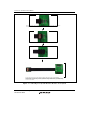
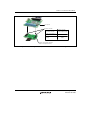
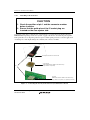
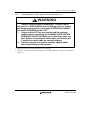
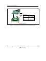
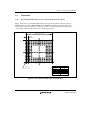
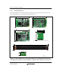
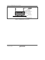
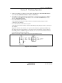
SH7216 Group PLBG0176GA-A
User System Interface Converter Board
R0E572167CBG10 User's Manual
Renesas Microcomputer Development Environment System
SuperHTM Family / SH7216 Series
R0E572167CBG10E
Rev.1.00 2010.07
Rev. 1.00 Jul 02, 2010 Page ii of xvi
REJ10J2185-0100
Notice
1.
All information included in this document is current as of the date this document is issued. Such information, however, is
subject to change without any prior notice. Before purchasing or using any Renesas Electronics products listed herein, please
confirm the latest product information with a Renesas Electronics sales office. Also, please pay regular and careful attention to
additional and different information to be disclosed by Renesas Electronics such as that disclosed through our website.
2.
Renesas Electronics does not assume any liability for infringement of patents, copyrights, or other intellectual property rights
of third parties by or arising from the use of Renesas Electronics products or technical information described in this document.
No license, express, implied or otherwise, is granted hereby under any patents, copyrights or other intellectual property rights
of Renesas Electronics or others.
3.
You should not alter, modify, copy, or otherwise misappropriate any Renesas Electronics product, whether in whole or in part.
4.
Descriptions of circuits, software and other related information in this document are provided only to illustrate the operation of
semiconductor products and application examples. You are fully responsible for the incorporation of these circuits, software,
and information in the design of your equipment. Renesas Electronics assumes no responsibility for any losses incurred by
you or third parties arising from the use of these circuits, software, or information.
5.
When exporting the products or technology described in this document, you should comply with the applicable export control
laws and regulations and follow the procedures required by such laws and regulations. You should not use Renesas
Electronics products or the technology described in this document for any purpose relating to military applications or use by
the military, including but not limited to the development of weapons of mass destruction. Renesas Electronics products and
technology may not be used for or incorporated into any products or systems whose manufacture, use, or sale is prohibited
under any applicable domestic or foreign laws or regulations.
6.
Renesas Electronics has used reasonable care in preparing the information included in this document, but Renesas Electronics
does not warrant that such information is error free. Renesas Electronics assumes no liability whatsoever for any damages
incurred by you resulting from errors in or omissions from the information included herein.
7.
Renesas Electronics products are classified according to the following three quality grades: "Standard", "High Quality", and
"Specific". The recommended applications for each Renesas Electronics product depends on the product's quality grade, as
indicated below. You must check the quality grade of each Renesas Electronics product before using it in a particular
application. You may not use any Renesas Electronics product for any application categorized as "Specific" without the prior
written consent of Renesas Electronics. Further, you may not use any Renesas Electronics product for any application for
which it is not intended without the prior written consent of Renesas Electronics. Renesas Electronics shall not be in any way
liable for any damages or losses incurred by you or third parties arising from the use of any Renesas Electronics product for an
application categorized as "Specific" or for which the product is not intended where you have failed to obtain the prior written
consent of Renesas Electronics. The quality grade of each Renesas Electronics product is "Standard" unless otherwise
expressly specified in a Renesas Electronics data sheets or data books, etc.
"Standard":
Computers; office equipment; communications equipment; test and measurement equipment; audio and visual
equipment; home electronic appliances; machine tools; personal electronic equipment; and industrial robots.
"High Quality": Transportation equipment (automobiles, trains, ships, etc.); traffic control systems; anti-disaster systems; anticrime systems; safety equipment; and medical equipment not specifically designed for life support.
"Specific":
Aircraft; aerospace equipment; submersible repeaters; nuclear reactor control systems; medical equipment or
systems for life support (e.g. artificial life support devices or systems), surgical implantations, or healthcare
intervention (e.g. excision, etc.), and any other applications or purposes that pose a direct threat to human life.
8.
You should use the Renesas Electronics products described in this document within the range specified by Renesas Electronics,
especially with respect to the maximum rating, operating supply voltage range, movement power voltage range, heat radiation
characteristics, installation and other product characteristics. Renesas Electronics shall have no liability for malfunctions or
damages arising out of the use of Renesas Electronics products beyond such specified ranges.
9.
Although Renesas Electronics endeavors to improve the quality and reliability of its products, semiconductor products have
specific characteristics such as the occurrence of failure at a certain rate and malfunctions under certain use conditions. Further,
Renesas Electronics products are not subject to radiation resistance design. Please be sure to implement safety measures to
guard them against the possibility of physical injury, and injury or damage caused by fire in the event of the failure of a
Renesas Electronics product, such as safety design for hardware and software including but not limited to redundancy, fire
control and malfunction prevention, appropriate treatment for aging degradation or any other appropriate measures. Because
the evaluation of microcomputer software alone is very difficult, please evaluate the safety of the final products or system
manufactured by you.
10.
Please contact a Renesas Electronics sales office for details as to environmental matters such as the environmental
compatibility of each Renesas Electronics product. Please use Renesas Electronics products in compliance with all applicable
laws and regulations that regulate the inclusion or use of controlled substances, including without limitation, the EU RoHS
Directive. Renesas Electronics assumes no liability for damages or losses occurring as a result of your noncompliance with
applicable laws and regulations.
11.
This document may not be reproduced or duplicated, in any form, in whole or in part, without prior written consent of Renesas
Electronics.
12.
Please contact a Renesas Electronics sales office if you have any questions regarding the information contained in this
document or Renesas Electronics products, or if you have any other inquiries.
(Note 1) "Renesas Electronics" as used in this document means Renesas Electronics Corporation and also includes its majorityowned subsidiaries.
(Note 2) "Renesas Electronics product(s)" means any product developed or manufactured by or for Renesas Electronics.
Rev. 1.00 Jul 02, 2010 Page iii of xvi
REJ10J2185-0100
Rev. 1.00 Jul 02, 2010 Page iv of xvi
REJ10J2185-0100
IMPORTANT INFORMATION
READ FIRST
• READ this user's manual before using this emulator product.
• KEEP the user's manual handy for future reference.
Do not attempt to use the emulator product until you fully understand its mechanism.
Emulator Product:
Throughout this document, the term "emulator product" shall be defined as the following
products produced only by Renesas Electronics Corp. and Renesas Solutions Corp. excluding all
subsidiary products.
•
•
•
•
•
•
•
•
E200F main unit
External bus trace unit
Evaluation-chip unit
Profiling expansion unit
Emulation memory unit
Common user-system interface adaptor cable
User-system interface converter board
Trace cable
The user system or a host computer is not included in this definition.
Purpose of the User System Interface Converter Board:
The user system interface converter board is used to connect the evaluation chip unit to the
user system. This user system interface converter board must only be used for the above purpose.
Limited Applications:
This emulator product is not authorized for use in transportation, vehicular, medical (where
human life is potentially at stake), aerospace, nuclear, or undersea repeater applications. Buyers of
this emulator product must notify Renesas Electronics Corporation, Renesas Solutions
Corporation or an authorized Renesas Electronics product distributor before planning to use the
product in such applications.
Improvement Policy:
Renesas Electronics Corp. (including its subsidiaries, hereafter collectively referred to as
Renesas) pursues a policy of continuing improvement in design, performance, and safety of the
emulator product. Renesas reserves the right to change, wholly or partially, the specifications,
design, user's manual, and other documentation at any time without notice.
Rev. 1.00 Jul 02, 2010 Page v of xvi
REJ10J2185-0100
Target User of the Emulator Product:
This emulator product should only be used by those who have carefully read and thoroughly
understood the information and restrictions contained in the user's manual. Do not attempt to use
the emulator product until you fully understand its mechanism.
It is highly recommended that first-time users be instructed by users that are well versed in the
operation of the emulator product.
Users are required to be familiar with the basic knowledge for the electric circuits, logic
circuits, and microcomputers.
Precautions to be Taken when Using This Product:
1. This emulator is a development supporting unit for use in your program development and
evaluation stages. In mass-producing your program you have finished developing, be sure to
make a judgment on your own risk that it can be put to practical use by performing integration
test, evaluation, or some experiment else.
2. In no event shall Renesas Solutions Corporation be liable for any consequence arising from the
use of this emulator.
3. Renesas Solutions Corporation strives to renovate or provide a workaround for product
malfunction at some charge or without charge. However, this does not necessarily mean that
Renesas Solutions Corporation guarantees the renovation or the provision under any
circumstances.
4. This emulator has been developed by assuming its use for program development and
evaluation in laboratories. Therefore, it does not fall under the application of Electrical
Appliance and Material Safety Law and protection against electromagnetic interference when
used in Japan.
5. This emulator does not conform to safety standards such as UL or IEC. Be careful when you
take this emulator overseas.
6. Renesas cannot anticipate every possible circumstance that might involve a potential hazard.
The warnings in this user's manual and on the emulator product are therefore not all inclusive.
Therefore, you must use the emulator product safely at your own risk.
Rev. 1.00 Jul 02, 2010 Page vi of xvi
REJ10J2185-0100
LIMITED WARRANTY
Renesas warrants its emulator products to be manufactured in
accordance with published specifications and free from defects in
material and/or workmanship. Renesas, at its option, will replace any
emulator products returned intact to the factory, transportation charges
prepaid, which Renesas, upon inspection, shall determine to be defective
in material and/or workmanship. The foregoing shall constitute the sole
remedy for any breach of Renesas’ warranty. See the Renesas warranty
booklet for details on the warranty period. This warranty extends only
to you, the original Purchaser. It is not transferable to anyone who
subsequently purchases the emulator product from you. Renesas is not
liable for any claim made by a third party or made by you for a third
party.
DISCLAIMER
RENESAS MAKES NO WARRANTIES, EITHER EXPRESS OR
IMPLIED, ORAL OR WRITTEN, EXCEPT AS PROVIDED
HEREIN, INCLUDING WITHOUT LIMITATION THEREOF,
WARRANTIES AS TO MARKETABILITY, MERCHANTABILITY,
FITNESS FOR ANY PARTICULAR PURPOSE OR USE, OR
AGAINST INFRINGEMENT OF ANY PATENT. IN NO EVENT
SHALL RENESAS BE LIABLE FOR ANY DIRECT, INCIDENTAL
OR CONSEQUENTIAL DAMAGES OF ANY NATURE, OR
LOSSES OR EXPENSES RESULTING FROM ANY DEFECTIVE
EMULATOR PRODUCT, THE USE OF ANY EMULATOR
PRODUCT, OR ITS DOCUMENTATION, EVEN IF ADVISED
OF THE POSSIBILITY OF SUCH DAMAGES. EXCEPT AS
EXPRESSLY STATED OTHERWISE IN THIS WARRANTY,
THIS EMULATOR PRODUCT IS SOLD "AS IS ", AND YOU
MUST ASSUME ALL RISK FOR THE USE AND RESULTS
OBTAINED FROM THE EMULATOR PRODUCT.
Rev. 1.00 Jul 02, 2010 Page vii of xvi
REJ10J2185-0100
State Law:
Some states do not allow the exclusion or limitation of implied warranties or liability for
incidental or consequential damages, so the above limitation or exclusion may not apply to you.
This warranty gives you specific legal rights, and you may have other rights which may vary from
state to state.
The Warranty is Void in the Following Cases:
Renesas shall have no liability or legal responsibility for any problems caused by misuse,
abuse, misapplication, neglect, improper handling, installation, repair or modifications of the
emulator product without Renesas’ prior written consent or any problems caused by the user
system.
All Rights Reserved:
1. Circuitry and other examples described herein are meant merely to indicate the characteristics
and performance of Renesas’ semiconductor products. Renesas assumes no responsibility for
any intellectual property claims or other problems that may result from applications based on
the examples described herein.
2. No license is granted by implication or otherwise under any patents or other rights of any third
party or Renesas.
3. This user's manual and emulator product are copyrighted and all rights are reserved by
Renesas. No part of this user's manual, all or part, may be reproduced or duplicated in any
form, in hard-copy or machine-readable form, by any means available without Renesas’ prior
written consent.
Figures:
Some figures in this user's manual may show items different from your actual system.
Rev. 1.00 Jul 02, 2010 Page viii of xvi
REJ10J2185-0100
SAFETY PAGE
READ FIRST
• READ this user's manual before using this emulator product.
• KEEP the user's manual handy for future reference.
Do not attempt to use the emulator product until you fully understand its mechanism.
DEFINITION OF SIGNAL WORDS
Either in the user's manual or on the product, several icons are used to insure proper
handling of this product and also to prevent injuries to you or other persons, or damage to
your properties. Their graphic images and meanings are given in this safety page. Be sure to
read this chapter before using the product.
This is the safety alert symbol. It is used to alert you to potential personal
injury hazards. Obey all safety messages that follow this symbol to avoid
possible injury or death.
DANGER
WARNING
CAUTION
CAUTION
DANGER indicates an imminently hazardous situation which, if not
avoided, will result in death or serious injury.
WARNING indicates a potentially hazardous situation which, if not
avoided, could result in death or serious injury.
CAUTION indicates a potentially hazardous situation which, if not
avoided, may result in minor or moderate injury.
CAUTION used without the safety alert symbol indicates a
potentially hazardous situation which, if not avoided, may result
in property damage.
NOTE emphasizes essential information.
In addition to the four above, the following are also used as appropriate.
Rev. 1.00 Jul 02, 2010 Page ix of xvi
REJ10J2185-0100
means WARNING or CAUTION.
Example:
CAUTION AGAINST AN ELECTRIC SHOCK
means PROHIBITION.
Example:
DISASSEMBLY PROHIBITED
means A FORCIBLE ACTION.
Example:
UNPLUG THE POWER CABLE FROM THE RECEPTACLE.
Rev. 1.00 Jul 02, 2010 Page x of xvi
REJ10J2185-0100
WARNING
Warnings for AC Power Supply:
• If
the attached AC power cable does not fit the
receptacle, do not alter the AC power cable and do not
plug it forcibly. Failure to comply may cause electric
shock and/or fire.
• Use
an AC power cable which complies with the safety
standard of the country.
• Do
not touch the plug of the AC power cable when your
hands are wet. This may cause electric shock.
• This
product is connected signal ground with frame
ground. If your developing product is transformless (not
having isolation transformer of AC power), this may cause
electric shock. Also, this may give an unrepairable
damage to this product and your developing one.
While developing, connect AC power of the product to
commercial power through isolation transformer in order
to avoid these dangers.
• If
other equipment is connected to the same branch
circuit care should be taken not to overload the circuit.
Refer to nameplate for electrical ratings.
•
When installing this equipment, insure that a reliable
ground connection is maintained.
Rev. 1.00 Jul 02, 2010 Page xi of xvi
REJ10J2185-0100
WARNING
• If
you smell a strange odor, hear an unusual sound, or
see smoke coming from this product, then disconnect
power immediately by unplugging the AC power cable
from the outlet.
Do not use this as it is because of the danger of electric
shock and/or fire. In this case, contact your local
distributor.
• When
installing or connecting this product with other
equipment, shut down AC power or disconnect the AC
power cord from the equipment to prevent personal injury
or damage to the equipment.
Warnings to Be Taken for This Product:
•
Do not disassemble or modify this product. Personal
injury due to electric shock may occur if this product is
disassembled and modified.
•
Make sure nothing falls into the cooling fan on the top
panel, especially liquids, metal objects, or anything
combustible.
Warning for Installation:
•
Do not set this product in water or areas of high
humidity. Make sure that the product does not get wet.
Spilling water or some other liquid into the product may
cause unrepairable damage.
Warning for Use Environment:
• This equipment is to be used in an environment with a
maximum ambient temperature of 35°C. Care should be
taken that this temperature is not exceeded.
Rev. 1.00 Jul 02, 2010 Page xii of xvi
REJ10J2185-0100
CAUTION
Cautions for AC Adapter:
• Use only the AC adapter included in this product
package.
•
The included AC adapter is for this emulator. Do not use it
for other product.
•
The DC plug on the included AC adapter has the below
polarity.
•
The included AC adapter has no power supply switch.
The AC adapter is always active while connecting the AC
power cable. Check if the power is supplied by the LED of
AC adapter.
Cautions to Be Taken for This Product:
•
Use caution when handling this product. Be careful not to
apply a mechanical shock.
•
Do not pull the main unit by the probe of the emulation
probe or the flexible cable which are connected to this
product. Excessive flexing or force of the flexible cable for
connecting this product to the emulation probe may break
connector.
Caution for Installation:
•
When in use do not place the emulator on its side.
Rev. 1.00 Jul 02, 2010 Page xiii of xvi
REJ10J2185-0100
WARNING
Observe the precautions listed below. Failure to do so
will result in a FIRE HAZARD and will damage the user
system and the emulator product or will result in
PERSONAL INJURY. The USER PROGRAM will be
LOST.
1. Do not repair or remodel the emulator product by
yourself for electric shock prevention and quality
assurance.
2. Always switch the E200F emulator and user system
OFF before connecting or disconnecting any CABLES or
PARTS.
3. Always before connecting any CABLES, make sure that
the pin 1 positions on both sides are correctly aligned.
Rev. 1.00 Jul 02, 2010 Page xiv of xvi
REJ10J2185-0100
Regulatory Compliance Notices
European Union Regulatory Notices on Electromagnetic Compatibility
CE Certifications:
This product complies with the following European EMC standards.
• EMC Directive 2004/108/EC
EN 55022 Class A
WARNING:
This is a Class A product. In a domestic environment this product
may cause radio interference in which case the user may be required
to take adequate measures.
EN 55024
Environmental Compliance and Certifications:
・WEEE Directive (2002/96/EC)
Renesas development tools and products are directly covered by the European Union's Waste Electrical and
Electronic Equipment, (WEEE), Directive 2002/96/EC. As a result, this equipment, including all accessories,
must not be disposed of as household waste but through your locally recognized recycling or disposal
schemes. As part of our commitment to environmental responsibility Renesas also offers to take back the
equipment and has implemented a Tools Product Recycling Program for customers in Europe. This allows
you to return equipment to Renesas for disposal through our approved Producer Compliance Scheme. To
register for the program, click here “http://www.renesas.com/weee".
Information for traceability:
・Authorised representative
Name:
Renesas Electronics Corp.
Address:
1753, Shimonumabe, Nakahara-ku, Kawasaki-shi, Kanagawa, 2118668,Japan
・Manufacturer
Name:
Renesas Solutions Corp.
Address:
Nippon Bldg., 2-6-2, Ote-machi, Chiyoda-ku, Tokyo 100-0004, Japan
・Person responsible for placing on the market
Name:
Renesas Electronics Europe Ltd.
Address:
Dukes Meadow, Millboard Road,BourneEnd,Buckinghamshire, SL8
5FH, U.K.
・Trademark and Type name
Trademark: Renesas
Product name:E200F Emulator
Type name: R0E572167CBG10
Rev. 1.00 Jul 02, 2010 Page xv of xvi
REJ10J2185-0100
United States Regulatory Notices on Electromagnetic Compatibility
FCC Certifications:
This equipment has been tested and found to comply with the limits for a Class A digital
device, pursuant to Part 15 of the FCC Rules. These limits are designed to provide reasonable
protection against harmful interference when the equipment is operated in a commercial
environment. This equipment generates, uses, and can radiate radio frequency energy and, if
not installed and used in accordance with the instruction manual, may cause harmful
interference to radio communications. Operation of this equipment in a residential area is
likely to cause harmful interference in which case the user will be required to correct the
interference at his own expense.
This device complies with Part 15 of the FCC Rules. Operation is subject to the following two
conditions: (1) this device may not cause harmful interference, and (2) this device must accept
any interference received, including interference that may cause undesired operation.
CAUTION:
Changes or modifications not expressly approved by the party responsible for
compliance could void the user's authority to operate the equipment.
Rev. 1.00 Jul 02, 2010 Page xvi of xvi
REJ10J2185-0100
Preface
The R0E572167CBG10 is a user system interface converter board that connects a user system for
the SH7216 in the PLBG0176GA-A package (Former package code: BP-176V) to the SH7216
E200F emulator (R0E0200F1EMU00 or R0E572160VKK00).
Contents
Section 1 Configuration.........................................................................................1
Section 2 Environmental Conditions..................................................................... 5
Section 3 Connection Procedures ..........................................................................7
3.1
3.2
3.3
3.4
Connecting User System Interface Board to User System.................................................... 7
3.1.1
Installing the IC Socket......................................................................................... 7
Connection to the User System When the Flexible Cable is in Use ..................................... 9
3.2.1
Assembling the User System Interface Cable....................................................... 9
3.2.2
Connecting User System Interface Board to EV-Chip Unit ............................... 12
3.2.3
Installing to the IC Socket .................................................................................. 14
Connection to the User System When the Flexible Cable is Not in Use ............................ 15
3.3.1
Mounting on the IC Socket................................................................................. 15
3.3.2
Connecting the Common User-System Interface Adaptor Cable
(Board Section) ................................................................................................... 16
3.3.3
Adjusting the Spacer Position............................................................................. 18
3.3.4
Connecting the User System Interface Board to EV-Chip Unit.......................... 19
Dimensions ......................................................................................................................... 21
3.4.1
Recommended Dimensions for User System Mount Pad (Footprint)................. 21
3.4.2
External Dimensions........................................................................................... 22
3.4.3
Dimensions of User System Interface Converter Board when Connected ......... 23
Section 4 Installing the MCU to the User System...............................................27
Section 5 Verifying Operation.............................................................................29
Section 6 Notice ..................................................................................................31
Section 1 Configuration
Section 1 Configuration
Figure 1 and table 1 show the external appearance and components, respectively, of the user
system interface converter board for the PLBG0176GA-A. Please make sure you have all of these
components when you unpack the product.
EV-chip unit
Common user-system interface
adaptor cable (board section)
When installing the MCU
Screws
(M2.0 x 10 mm)
The IC socket
for installing the MCU
x3
Common user-system interface
adaptor cable (flexible cable sections )
MCU
User-system interface converter board
IC socket plug
IC socket
User system
Figure 1 Appearance of the User-System Interface Converter Board for SH7216 Group
Products in the PLBG0176GA-A Package
Rev. 1.00 Jul 02, 2010 Page 1 of 32
REJ10J2185-0100
Section 1 Configuration
CAUTION
Use the following item with the IC socket for PLBG0176GA-A
package on the user system:
CSPLUG/W176A1513RE01 IC-socket plug (manufactured by
Tokyo Eletech Corporation).
To connect the emulator with the user-system interface
converter board for the PLBG0176GA-A, the common adaptor
cable (R0E200F1CKL11) for the interface board must be
obtained separately.
The BSSOCKET176A1513RE21N IC socket and
LSPACK176A1513RE01 IC socket for mounting the MCU (both
are manufactured by Tokyo Eletech Corporation) are also to
be purchased separately. Please contact Tokyo Eletech
Corporation for details.
Rev. 1.00 Jul 02, 2010 Page 2 of 32
REJ10J2185-0100
Section 1 Configuration
Table 1
R0E572167CBG10 Components
No. Component
Quantity
Remarks
1
User-system interface
PLBG0176GA-A converter
board
1
R0E572167CBG10
2
IC socket plug
1
CSPLUG/W176A1513RE01 for use to connect the
socket for PLBG0176GA-A package
3
User’s manual
1
User’s manual for R0E572167CBG10 (this manual)
Rev. 1.00 Jul 02, 2010 Page 3 of 32
REJ10J2185-0100
Section 1 Configuration
Rev. 1.00 Jul 02, 2010 Page 4 of 32
REJ10J2185-0100
Section 2 Environmental Conditions
Section 2 Environmental Conditions
Maintain the conditions in table 2 when using the emulator.
Table 2
Environmental Conditions
Item
Specifications
Temperature
Operating: +10 to +35°C
Storage: -10 to +35°C
Humidity
Operating: 35 to 80% RH, no condensation
Storage: 35 to 80% RH, no condensation
Vibration
Operating: 2.45 m/s max.
2
Storage: 4.9 m/s max.
2
Transportation: 14.7 m/s max.
Ambient gases
There must be no corrosive gases present.
2
Rev. 1.00 Jul 02, 2010 Page 5 of 32
REJ10J2185-0100
Section 2 Environmental Conditions
Rev. 1.00 Jul 02, 2010 Page 6 of 32
REJ10J2185-0100
Section 3 Connection Procedures
Section 3 Connection Procedures
3.1
Connecting User System Interface Board to User System
WARNING
Always switch OFF the user system and the emulator
product before the USER-SYSTEM INTERFACE CONVERTER
BOARD is connected to or removed from any part. Before
connecting, make sure that pin 1 on both sides are correctly
aligned. Failure to do so will result in a FIRE HAZARD and will
damage the user system and the emulator product or will
result in PERSONAL INJURY. The USER PROGRAM will be
LOST.
3.1.1
Installing the IC Socket
Solder the IC socket (BSSOCKET176A1513RE21N manufactured by Tokyo Eletech Corporation,
for separate purchase) for the PLBG0176GA-A package to the user system.
Rev. 1.00 Jul 02, 2010 Page 7 of 32
REJ10J2185-0100
Section 3 Connection Procedures
CAUTION
1. Apply the solder paste to the BGA pads on the user
system. Be careful to keep the thickness of the solder
within 100 to 150 micro-meters. Applying too much solder
will cause short circuiting between the pins.
2. To avoid the scattering (dispersal) of flux from other
components at the solder reflow , the protective tape
(polimide tape) is affixed to the section for connection of
the IC plug. Do not peel off the protective tape until the
solder reflow is over.
3. Do not install compnents that occupy large volume
close to the IC socket. Such components will prevent
the convective flow of heat during reflow.
4. Do not use flux etc. to clean the IC socket.
Rev. 1.00 Jul 02, 2010 Page 8 of 32
REJ10J2185-0100
Section 3 Connection Procedures
3.2
Connection to the User System When the Flexible Cable is in Use
The IC socket on the user system is connected with the emulator in either of two ways
according to whether or not the flexible cable section of the common cable for the user system
interface is in use. Refer to this section (section 3.2, Connection to the User System When the
Flexible Cable is in Use) or section 3.3, Connection to the User System When the Flexible
Cable is Not in Use, according to whether or not the flexible cable is in use.
While the flexible cable leads to longer delay times for generated signals to reach the device
from the IC socket, the area taken up on the emulator board for the user system is smaller. This
form of connection is thus applicable to a wider variety of layouts for the user system. Refer to
point 3 of section 5 for details on the delay time.
3.2.1
Assembling the User System Interface Cable
CAUTION
Check the location of pin 1 and the connector number before
insertion.
•
Connecting the user system interface cable
Use the flexible cable section of the common cable for the user system interface to connect the
board section of the common cable for the user system interface with the user-system interface
converter board (see figures 2 and 3).
Rev. 1.00 Jul 02, 2010 Page 9 of 32
REJ10J2185-0100
Section 3 Connection Procedures
Connect the flexible cable to CONNECTOR1 mounted on the board section of the common
user-system interface adaptor cable as shown below .
After that, connect the flexible cable to CONNECTOR2.
Connect the flexible cable to CONNECTOR3.
Connect the common user-system interface adaptor cable with the user-system interface
PLQP0176KB-A converter board, with each of the three flexible cable sections of the adaptor cable
connected to the corresponding connector ([CONNECTOR1], [CONNECTOR2], or [CONNECTOR3])
on the converter board .
Figure 2 Connecting User System Interface Board to User System
Rev. 1.00 Jul 02, 2010 Page 10 of 32
REJ10J2185-0100
Section 3 Connection Procedures
When removing the flexible cable from a converter board or a board section of
the adaptor cable, keep the board in place, hold both sides of the connector at
the head of the cable, and apply vertical force to pull the cable away. If the join
is stiff so that the cable is difficult to remove, pull the cable head up from the
right or left side. Do not apply pressure in the direction marked "X", since this
will damage the connector.
Figure 3 Removing the Flexible Cable
Rev. 1.00 Jul 02, 2010 Page 11 of 32
REJ10J2185-0100
Section 3 Connection Procedures
3.2.2
Connecting User System Interface Board to EV-Chip Unit
WARNING
Observe the precautions listed below. Failure to do so will
result in a FIRE HAZARD and will damage the user system and
the emulator product or will result in PERSONAL INJURY. The
USER PROGRAM will be LOST.
1. Always switch OFF the user system and the emulator
product before connecting the COMMON USER-SYSTEM
INTERFACE ADAPTOR CABLE to or removing it from any
part. Before connecting the cable, make sure that the pin
1 positions on both sides are correctly aligned.
2. Use the common user-system interface adaptor cable that
is specifically for the emulator.
1. Make sure the user system and emulator are turned off.
2. Align the connectors on the board with those on the EV-chip unit according to their numbers
(figure 4).
Rev. 1.00 Jul 02, 2010 Page 12 of 32
REJ10J2185-0100
Section 3 Connection Procedures
EV-chip unit
Connector number
Connector number
on the user-system
interface adaptor cable
EV-chip unit
connector number
User I/F Connector 1
(CN4)
UCN1
User I/F Connector 2
(CN5)
UCN2
Common user-system interface
adaptor cable (board section)
Figure 4 Connecting the User System Interface Board to the EV-Chip Unit
Rev. 1.00 Jul 02, 2010 Page 13 of 32
REJ10J2185-0100
Section 3 Connection Procedures
3.2.3
Installing to the IC Socket
CAUTION
1. Check the position of pin 1 and the connector number
before insertion.
2. Ensure that the guide pins of the IC socket plug are
inserted on the user system side.
Use the IC socket plug to affix the user system interface converter board to the IC socket for
PLBG0176GA-A package on the user system. Apply vertical force to fasten the parts together.
Take particular care to align the positions of pin 1 and the guide pin and to avoid the application
of twisting force that might damage the soldered joint connector for ICE.
User-system interface converter board
IC socket plug
(CSPLUG/W176A1513RE01N manufactured by
Tokyo Eletech Corporation)
Pin 1
User system
IC socket
(BSSOCKET176A1513RE21N manufactured by
Tokyo Eletech Corporation, for separate purchase)
Figure 5 Connecting the User System and User System Interface Board
Rev. 1.00 Jul 02, 2010 Page 14 of 32
REJ10J2185-0100
Section 3 Connection Procedures
3.3
Connection to the User System When the Flexible Cable is Not in Use
While the connection takes up a larger area on the emulator board for the user system when the
flexible cable is not in use, delay times for generated signals to reach the device from the IC
socket are shorter. This form of connection is thus applicable when the cable connection is leading
to insufficient timing margins. Refer to point 3 of section 5, Verifying Operation, for details on
the delay time.
3.3.1
Mounting on the IC Socket
Use the IC socket plug to affix the user system interface converter board to the IC socket for
PLBG0176GA-A package on the user system. Apply vertical force to fasten the parts together.
Take particular care to align the positions of pin 1 and the guide pin and to avoid the application
of twisting force that might damage the soldered joint connector for ICE.
User-system interface converter board
IC socket plug
(CSPLUG/W176A1513RE01 manufactured by
Tokyo Eletech Corporation)
Pin 1
IC socket
(BSSOCKET176A1513RE21N manufactured by
Tokyo Eletech Corporation, for separate purchase)
User system
Figure 6 Connecting the User System and User System Interface Board
Rev. 1.00 Jul 02, 2010 Page 15 of 32
REJ10J2185-0100
Section 3 Connection Procedures
3.3.2
Connecting the Common User-System Interface Adaptor Cable (Board Section)
CAUTION
Check the position of pin 1 and the connector number before
insertion.
Ensure that the positions of [CONNECTOR1], [CONNECTOR2], or [CONNECTOR3] on the
common user-system interface adaptor cable match the positions of [CONNECTOR1],
[CONNECTOR2], or [CONNECTOR3] on the user-system interface converter board, and connect
the cable to the board. When they are correctly connected, the six guide pins on the user-system
interface converter board will enter the holes on the board section of the common user-system
interface adaptor cable.
Rev. 1.00 Jul 02, 2010 Page 16 of 32
REJ10J2185-0100
Section 3 Connection Procedures
Common user-system interface
adaptor cable (board section)
Spacer
Guide pin
Common user-system interface
converter board
User system
Figure 7 Connecting the Common User-System Interface Adaptor Cable (Board Section)
Rev. 1.00 Jul 02, 2010 Page 17 of 32
REJ10J2185-0100
Section 3 Connection Procedures
3.3.3
Adjusting the Spacer Position
Adjust the positions of the spacers mounted on the four corners of the common user- system
interface adaptor board so that they are in contact with the user system.
Common user-system interface
adaptor cable (board section)
Spacer
Spacer
User system
Figure 8 Adjusting the Spacer Position
Rev. 1.00 Jul 02, 2010 Page 18 of 32
REJ10J2185-0100
Section 3 Connection Procedures
3.3.4
Connecting the User System Interface Board to EV-Chip Unit
WARNING
Observe the precautions listed below. Failure to do so
will result in a FIRE HAZARD and will damage the user system
and the emulator product or will result in PERSONAL INJURY.
The USER PROGRAM will be LOST.
1. Always switch OFF the user system and the emulator
product before connecting the COMMON USER-SYSTEM
INTERFACE ADAPTOR CABLE to or removing it from any
part. Before connecting the cable, make sure that the pin
1 positions on both sides are correctly aligned.
2. Use the common user-system interface adaptor cable
that is specifically for the emulator.
1. Make sure the user system and emulator are turned off.
2. Align the connectors on the board with those on the EV-chip unit according to their numbers
(figure 9).
Rev. 1.00 Jul 02, 2010 Page 19 of 32
REJ10J2185-0100
Section 3 Connection Procedures
EV-chip unit
Connector number
EV-chip unit
connector number
Connector number
on the user-system
interface adaptor cable
User I/F Connector 1
(CN4)
UCN1
User I/F Connector 2
(CN5)
UCN2
Common user-system interface
adaptor cable (board section)
Figure 9 Connecting the User System Interface Board to the EV-Chip Unit
Rev. 1.00 Jul 02, 2010 Page 20 of 32
REJ10J2185-0100
Section 3 Connection Procedures
3.4
Dimensions
3.4.1
Recommended Dimensions for User System Mount Pad (Footprint)
Figure 10 shows the recommended dimensions of the pads for mounting of the IC socket for
PLBG0176GA-A package (BSSOCKET176A1513RE21N manufactured by Tokyo Eletech
Corporation, for separate purchase) on the user system (i.e. the footprint of the socket). Please
contact Tokyo Eletech Corporation for the details of the pattern.
0.8 x 14 = 11.2
0.8
φ0.5
Dimensions and tolerance
Dimensions
Tolerance
±0.05
to 1.2
±0.10
1.3 to 2.0
±0.15
2.1 to 5.0
±0.20
5.1 to 10.0
±0.30
10.1 to
Unit: mm
Figure 10 Recommended Dimensions for Mount Pad
Rev. 1.00 Jul 02, 2010 Page 21 of 32
REJ10J2185-0100
Section 3 Connection Procedures
3.4.2
External Dimensions
The external dimensions of the EV-chip unit, common user-system interface adaptor cable, and
user-system interface converter board are shown in figure 11.
125.0
90.0
90.0
125.0
External bus trace unit
125.0
60.0
90.0
90.0
110.0
20.0
49.0
5.81
Emulation memory unit
EV-chip unit
Common user-system interface adaptor cable (board section)
267.0
35.0
241.0
Common user-system interface adaptor cable (flexible cable sections)
35.0
44.5
User-system interface converter board
Unit: mm
Tolerance: ±0.5 mm
Figure 11 External Dimensions of the External Bus Trace Unit, Emulation Memory Unit,
EV-Chip Unit, Common User-System Interface Adaptor Cables, and the Converter Board
Rev. 1.00 Jul 02, 2010 Page 22 of 32
REJ10J2185-0100
Section 3 Connection Procedures
3.4.3
Dimensions of User System Interface Converter Board when Connected
Dimensions of the user system interface converter board when it is connected to the user system
are shown in figures 12 to 15.
10.6
IC socket plug
(CSPLUG/W176A1513RE01N
manufactured by
Tokyo Eletech Corporation)
IC socket
(BSSOCKET176A1513RE21N
manufactured by
Tokyo Eletech Corporation,
for separate purchase)
17.0
14
35.0
13.5
18.8
User-system interface converter board
13
44.5
Pin 1
Figure 12 Dimensions of the User-System Interface Converter Board when Connected to
the User System (Connection Includes the Flexible Cable)
Rev. 1.00 Jul 02, 2010 Page 23 of 32
REJ10J2185-0100
Section 3 Connection Procedures
Emulation memory unit
External bus trace unit
27.9
10.6
15.4
53.8
71.3
EV-chip unit
22.0
Spacer (φ6.0)
37.5
22.5
30.0
30.0
User system
27.5
IC socket
(BSSOCKET176A1513RE21N
manufactured by
Tokyo Eletech Corporation)
24.5
24.5
39.19
39.19
User system
Pin 1
Top view
Unit: mm
Tolerance: ±1.0 mm
Figure 13 Dimensions of the User System and Connected User-System Interface Converter
Board (with the External Bus Trace Unit, Emulation Memory Unit, and EV-chip Unit also
Connected)
Rev. 1.00 Jul 02, 2010 Page 24 of 32
REJ10J2185-0100
Section 3 Connection Procedures
External bus trace unit
27.9
10.6
15.4
40.8
58.3
EV-chip unit
22.0
Spacer (φ6.0)
37.5
22.5
30.0
30.0
User system
27.5
IC socket
(BSSOCKET176A1513RE21N
manufactured by
Tokyo Eletech Corporation)
24.5
24.5
39.19
39.19
User system
Pin 1
Top view
Unit: mm
Tolerance: ±1.0 mm
Figure 14 Dimensions of the User System and Connected User-System Interface Converter
Board (with the External Bus Trace Unit and EV-chip Unit also Connected)
Rev. 1.00 Jul 02, 2010 Page 25 of 32
REJ10J2185-0100
Section 3 Connection Procedures
22.0
Spacer (φ6.0)
37.5
22.5
30.0
30.0
27.9
27.9
10.6
15.4
45.4
EV-chip unit
User system
27.5
IC socket
(BSSOCKET 176A1513RE21N
manufactured by
Tokyo Eletech Corporation)
24.5
24.5
39.19
User system
39.19
Pin 1
Top view
Unit: mm
Tolerance: ±1.0 mm
Figure 15 Dimensions of the User System and Connected User-System Interface Converter
Board (with the EV-chip Unit also Connected)
Rev. 1.00 Jul 02, 2010 Page 26 of 32
REJ10J2185-0100
Section 4 Installing the MCU to the User System
Section 4 Installing the MCU to the User System
CAUTION
1. Check the location of pin 1 before inserting.
2. Use a Phillips-head screwdriver whose head matches the
screw head.
3. The tightening torque must be 0.054 Nom or less. If the
applied torque cannot be accurately measured, stop
tightening when the force required to turn the screw
becomes significantly greater than that needed when first
tightening. If a screw is tightened too much, the screw
head may break or an IC socket contact error may be
caused by a crack in the IC socket solder.
4. If the MCU does not operate correctly, cracks might have
occurred in the solder. Check conduction with a tester and
re-solder the IC socket if necessary.
To mount the MCU on the user system, use an IC socket (BSSOCKET176A1513RE21N, Tokyo
Eletech Corporation, for separate purchase) and LSPACK (LSPACK176A1513RE01, Tokyo
Eletech Corporation, for separate purchase), along with the guide board, spacer and cover for the
IC socket.
1. Fit the BSSOCKET to the guide section of the LSPACK.
2. Place the guide board and spacer on the LSPACK. Adjust the guide points of the spacer to the
LSPACK and the opening for components in the guide board.
3. Place the MCU gently in the opening of the spacer. Be sure to correctly align pin 1 of the MCU
with the IC socket.
4. Put the top cover on the spacer. The four holes at the four corners of the spacer and of the cover
must be aligned. Use the four screws to fasten the cover to the IC socket. Each screw in turn
should be made a little tighter, alternating between screws on opposing corners. Use the
screwdriver provided with the package. The torque in tightening must be 0.054 N·m or less.
5. When removing the cover from the LSPACK, hold the side of the cover so that no stress is
applied to the solder connections between the LSPACK and CS/BSSOCKET while the screws on
the cover are being unscrewed.
Rev. 1.00 Jul 02, 2010 Page 27 of 32
REJ10J2185-0100
Section 4 Installing the MCU to the User System
Four screws
Top cover
Spacer
Guide board
LSPACK
BSSOCKET
Target board
Figure 16 Installing MCU to User System
Rev. 1.00 Jul 02, 2010 Page 28 of 32
REJ10J2185-0100
Section 5 Verifying Operation
Section 5 Verifying Operation
1. Turn on the emulator according to the procedures described in the SH7216 E200F Emulator
User's Manual (R0E0200F1EMU00J or R0E572160EMU00J).
2. The emulator connected to this user-system interface converter board supports two kinds of
clock sources as the MCU clock. For details, refer to the SH7216 E200F Emulator User's
Manual (R0E0200F1EMU00J).
⎯ To use the emulator internal clock
Select the [Emulator Internal Clock] in the [Select Emulation] dialog displayed when
connecting to the emulator.
⎯ To use the external clock on the user system
Select the [User System Clock] in the [Select Emulation] dialog displayed when connecting to
the emulator.
Supply the external clock from the user system to the emulator by inputting the EXTAL pin
(pin E14) on the user-system interface converter board or connecting the crystal oscillator to
the XTAL (pin E15) and EXTAL pins. For details, refer to section 4, Clock Pulse Generator,
in the SH7216 Group Hardware Manual.
Figure 17 shows the clock oscillator on the user system interface board.
H C U04
1 MΩ
H C U04
H C U04
H C U04
22 Ω
To E200F
em ulator
H C U04
H C U04
270 Ω
EXTAL
XT AL
Sys tem c loc k
Figure 17 Clock Oscillator
Rev. 1.00 Jul 02, 2010 Page 29 of 32
REJ10J2185-0100
Section 5 Verifying Operation
3.
When connecting the E200F emulator and the user system with the common user-system
interface adaptor cable and the user system converter board, the wiring of the circuit between
the IC socket pins and pins of the devices on the user system leads to delay times for the
signals.
⎯ When the connection includes the flexible cable
Table 3 gives the delay times when the common user-system interface cable is used with the
supplied flexible cable.
Table 3
Delay Times Created by Connection with the Flexible Cable
No. Signal Name
Delay Time (ns)
1
_RES
22
2
NMI
19
3
Other signals
6
⎯ When the connection does not include the flexible cable
Table 4 shows the delay time generated when the supplied flexible cable has been removed
from the common user-system interface adaptor cable.
Table 4
Delay Times Created by Connection without the Flexible Cable
No. Signal Name
Delay Time (ns)
1
_RES
19
2
NMI
16
3
Other signals
3
Rev. 1.00 Jul 02, 2010 Page 30 of 32
REJ10J2185-0100
Section 6 Notice
Section 6 Notice
1. Before connecting any parts or cables, make sure that pin 1 on the both sides are correctly
aligned.
2. Do not apply excessive force to the user-system interface converter board while it is connected
to the user system.
3. The dimensions of the recommended mount pad for the IC socket for this user-system
interface converter board are different from those of the MCU.
4. This user-system interface converter board is specifically designed for the SH7216 E200F
EV-chip unit (R0E572160VKK00). Do not use this board with any other emulator.
5. When power is not supplied to the VCCQ pin on the user-system interface converter board, the
emulator displays ** VCC DOWN. The emulator will not operate correctly.
Rev. 1.00 Jul 02, 2010 Page 31 of 32
REJ10J2185-0100
Section 6 Notice
Rev. 1.00 Jul 02, 2010 Page 32 of 32
REJ10J2185-0100
SH7216 Group PLBG0176GA-A
User System Interface Converter Board
R0E572167CBG10 User's Manual
Publication Date: Rev.1.00, July 2, 2010
Published by:
Renesas Electronics Corporation
http://www.renesas.com
SALES OFFICES
Refer to "http://www.renesas.com/" for the latest and detailed information.
Renesas Electronics America Inc.
2880 Scott Boulevard Santa Clara, CA 95050-2554, U.S.A.
Tel: +1-408-588-6000, Fax: +1-408-588-6130
Renesas Electronics Canada Limited
1101 Nicholson Road, Newmarket, Ontario L3Y 9C3, Canada
Tel: +1-905-898-5441, Fax: +1-905-898-3220
Renesas Electronics Europe Limited
Dukes Meadow, Millboard Road, Bourne End, Buckinghamshire, SL8 5FH, U.K
Tel: +44-1628-585-100, Fax: +44-1628-585-900
Renesas Electronics Europe GmbH
Arcadiastrasse 10, 40472 Düsseldorf, Germany
Tel: +49-211-65030, Fax: +49-211-6503-1327
Renesas Electronics (China) Co., Ltd.
7th Floor, Quantum Plaza, No.27 ZhiChunLu Haidian District, Beijing 100083, P.R.China
Tel: +86-10-8235-1155, Fax: +86-10-8235-7679
Renesas Electronics (Shanghai) Co., Ltd.
Unit 204, 205, AZIA Center, No.1233 Lujiazui Ring Rd., Pudong District, Shanghai 200120, China
Tel: +86-21-5877-1818, Fax: +86-21-6887-7858 / -7898
Renesas Electronics Hong Kong Limited
Unit 1601-1613, 16/F., Tower 2, Grand Century Place, 193 Prince Edward Road West, Mongkok, Kowloon, Hong Kong
Tel: +852-2886-9318, Fax: +852 2886-9022/9044
Renesas Electronics Taiwan Co., Ltd.
7F, No. 363 Fu Shing North Road Taipei, Taiwan
Tel: +886-2-8175-9600, Fax: +886 2-8175-9670
Renesas Electronics Singapore Pte. Ltd.
1 harbourFront Avenue, #06-10, keppel Bay Tower, Singapore 098632
Tel: +65-6213-0200, Fax: +65-6278-8001
Renesas Electronics Malaysia Sdn.Bhd.
Unit 906, Block B, Menara Amcorp, Amcorp Trade Centre, No. 18, Jln Persiaran Barat, 46050 Petaling Jaya, Selangor Darul Ehsan, Malaysia
Tel: +60-3-7955-9390, Fax: +60-3-7955-9510
Renesas Electronics Korea Co., Ltd.
11F., Samik Lavied' or Bldg., 720-2 Yeoksam-Dong, Kangnam-Ku, Seoul 135-080, Korea
Tel: +82-2-558-3737, Fax: +82-2-558-5141
© 2010 Renesas Electronics Corporation and Renesas Solutions Corp. All rights reserved.
Colophon 1.0
SH7216 Group PLBG0176GA-A
User System Interface Converter Board
R0E572167CBG10 User's Manual
REJ10J2185-0100