1
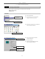
M371E
ECLIPSE LV Series Support Tools
(Setup software for ECLIPSE LV series microscopes)
Software Manual
06.1.NF.1 (3/3)
Introduction
Thank you for purchasing the Nikon products.
This manual describes how to install and use the ECLIPSE LV Series Support Tools
software for ECLIPSE LV series microscopes. To ensure correct use, please read this
manual carefully before operating the product.
Refer to the hardware manual for detailed information on how to connect your microscope
and discussions of the system configuration.
• Copyright laws prohibit the copying of this manual, in whole or in part, without written
permission from Nikon.
• The contents of this manual are subject to change without notice.
• Although every effort has been made to ensure the accuracy of this manual, errors or
inconsistencies may remain. If you note any points that are unclear or incorrect, please
contact your nearest Nikon representative.
• Read the instruction manuals provided with your microscope and computer.
Prerequisite knowledge
This manual assumes a basic familiarity with Windows. If you come across unfamiliar
terms or operations while reading through this manual, consult the user's manual for your
version of Windows.
About the example screens used in the manual
This manual describes various operations in Windows 2000/XP using Windows 2000
screens as examples. Procedures are virtually identical for Windows 2000 and XP.
Depending on the specific OS type or version, the actual appearance of the screen or
operations may not correspond precisely to the example screens shown at various points
throughout the manual. For information on operations or screens specific to your OS
version, please consult the OS user's manual.
Trademarks
Microsoft and Windows are registered trademarks of Microsoft Corporation in the U.S.
and other countries.
Pentium is a registered trademark of Intel Corporation in the U.S. and other countries.
Other company and product names occurring in this manual are the trademarks or
registered trademarks of their respective companies.
This manual omits trademark indications such as TM and ® for various trademarks or
registered trademarks.
Disclaimer
Nikon shall not be liable for any damages and problems on user side or on a third-party
side, which may result from the use of this software.
Contents
1.
Preparations ...................................................................................................................... 3
1.1
1.2
1.3
Hardware and Software Requirements.................................................................... 3
1.1.1
Checking Available RAM .................................................................................4
1.1.2
Checking the Free Hard Disk Space ...............................................................5
Installing the Application Software........................................................................... 6
1.2.1
Closing All Other Application Software ............................................................6
1.2.2
Running the Setup Wizard...............................................................................7
1.2.3
Installing Device Drivers ................................................................................10
Uninstalling the Application Software .................................................................... 14
2.
LV Series Support Tools Configuration............................................................................ 15
3.
LV Setup ......................................................................................................................... 16
3.1
LVSetup Workflow................................................................................................. 16
3.1.1
3.2
Setting Item List .............................................................................................17
Starting and Ending LVSetup ................................................................................ 19
3.2.1
Starting Up.....................................................................................................19
3.2.2
Ending the Software ......................................................................................20
3.3
Layout of the LVSetup Main Window..................................................................... 21
3.4
Setting Up the Microscope System........................................................................ 22
3.5
Microscope System Configuration ......................................................................... 23
3.5.1
3.6
3.7
3.8
3.9
Returning the Settings to the Factory Default Condition................................24
LVSetup Condition ................................................................................................ 25
3.6.1
Entering the Name of the Microscope System ..............................................25
3.6.2
Selecting the Setup Mode .............................................................................26
Setting Up Objectives............................................................................................ 29
3.7.1
Objective Settings..........................................................................................29
3.7.2
Objective Settings (Registering New Objectives) ..........................................30
3.7.3
Special Control Settings ................................................................................31
Filter Cube Setup .................................................................................................. 32
3.8.1
Filter Cube Settings .......................................................................................33
3.8.2
Filter Cube Settings (Registering New Filter Cubes) .....................................34
3.8.3
Registering New Filters..................................................................................35
Interlock ................................................................................................................ 36
3.9.1
Setting Up the Interlock Control.....................................................................38
3.10
Settings for Other Control Items ............................................................................ 40
3.11
Data Transfer Process .......................................................................................... 43
3.12
Password Settings ................................................................................................ 44
2
1
Preparations
This chapter describes hardware and software requirements for Nikon ECLIPSE LV Series Support Tools
and how to install and uninstall the software.
1.1
Hardware and Software Requirements
CAUTION
• Before installing Nikon ECLIPSE LV Series Support Tools, confirm that your
computer meets the minimum requirements given below for memory and
available hard disk space.
• Install the application software before connecting your computer and
microscope system (LV100DA or LV-ECON).
Personal computer main unit
Item
Condition
CPU
Pentium III 1 GHz or higher
Memory
256 MB or more
Hard disk drive
Minimum of 100 MB free space
Video RAM
16 MB or more
OS
Windows 2000 (Japanese or English version)
Note: Use Windows 2000 Professional Service Pack 4 or later.
Windows XP (Japanese or English version)
Note: Use Windows XP Professional Service Pack 2 or later.
"Nikon ECLIPSE LV Series Support Tools" is supplied in CD-ROM. A
CD-ROM drive is required to read and install the software.
Other
Display
Item
Resolution
Condition
1,024 x 768 pixels. A monitor/video card capable of True Color output is
recommended.
"LV Series Support Tools" is not guaranteed to be compatible with all personal computers. Please
contact your distributor for detailed compatibility information.
3
Chapter 1
1.1
Preparations
Hardware and Software Requirements
Checking Available RAM
1.1.1
Use the System Properties dialog box to check the amount of free RAM.
[Memory requirements]
256 MB or more
Procedure
d Start menu
(1) Click the Start button.
(2) Choose Settings, then Control Panel to
(2) Choose Settings, then
Control Panel.
display the Control Panel window.
(1) Click the Start button.
d Control Panel window
(3) Double-click the System icon to display the
System Properties dialog box.
(3) Double-click the System icon.
d System Properties dialog box
(4) Click the General tab of the System
(4) Click the General tab.
Properties dialog box.
(5) Check free memory.
(6) Click OK or Cancel button to close the
System Properties dialog box.
(5) Check free memory
here.
(6) Click OK or Cancel
button.
4
Chapter 1
1.1
1.1.2
Preparations
Hardware and Software Requirements
Checking the Free Hard Disk Space
The free hard disk space can be confirmed in the My Computer window. If you have insufficient hard disk
space, remove any unnecessary applications from the hard disk to increase available free space.
[Hard disk drive]
Must have 100 MB or more free space.
Procedure
d Desktop
(1) Double-click the My Computer icon to
display the My Computer window.
(1) Double-click the My
Computer icon.
d My Computer window
(2) Right-click on the Drive icon in the My
Computer window to which you want to
install the application.
(2) Right-click on the Drive
icon.
(3) Click Properties in the shortcut menu to
display the Properties dialog box for the
selected drive.
(3) Click Properties.
d (Drive) Properties dialog box
(4) Click the General tab of the Properties
(4) Click the General tab.
dialog box.
(5)
Check the amount of free space on the
hard disk.
(5) Check the amount of free
hard disk space.
(6) Click OK or Cancel button to close the
(Drive) Properties dialog box.
(6) Click OK or Cancel button.
5
Chapter 1
1.2
1.2
Preparations
Installing the Application Software
Installing the Application Software
You are now ready to install Nikon ECLIPSE LV Series Support Tools.
CAUTION
• Install the application software before connecting the personal computer
and microscope system.
• To install the Nikon ECLIPSE LV Series Support Tools, you must login to
your computer with a user account with Administrator rights.
1.2.1
Closing All Other Application Software
Before installing Nikon ECLIPSE LV Series Support Tools, close all system-resident programs such as
the screensaver and anti-virus utility.
Closing the screensaver
d Shortcut menu on the desktop
(1) Right-click on the desktop to display a
(1) Right-click on the
desktop.
shortcut menu.
(2) Click Properties in the shortcut menu to
display the Display Properties dialog box.
(2) Click Properties.
d Display Properties dialog box
(3) Click the Screen Saver tab of the Display
(3) Click the Screen Saver
tab.
Properties dialog box.
(4) Click the Screen Saver text box and select
"None" from the list.
(5) Click the OK button.
(4) Select "None".
(5) Click the OK button.
6
Chapter 1
1.2
1.2.2
Preparations
Installing the Application Software
Running the Setup Wizard
To install the application software, run the setup wizard from the CD-ROM and follow the on-screen
instructions.
CAUTION
• To install the Nikon ECLIPSE LV Series Support Tools, you must login as
Administrator.
• For information on uninstalling Nikon ECLIPSE LV Series Support Tools,
refer to Section 1.3, “Uninstalling the Application Software.”
Normally, the setup wizard runs automatically when you insert the CD-ROM into the CD-ROM drive of
your computer. If the setup wizard does not start, follow the procedure given below to start it.
Starting the setup wizard
d Desktop
(1) Double-click the My Computer icon to
display the My Computer window.
(1) Double-click the My Computer icon.
d My Computer window
(2) Double-click the CD-ROM icon to display
the CD-ROM window.
(2) Double-click the CD-ROM
icon.
d CD-ROM window
(3) Double-click the Setup icon to start the
setup wizard.
(3) Double-click the Setup
icon.
7
Chapter 1
1.2
Preparations
Installing the Application Software
Installation procedure
d Setup wizard startup screen
The Setup Menu opens automatically when you
insert the CD-ROM into the CD-ROM drive of
your computer.
(1) Click the Next button.
(1) Click the Next button.
d Installation folder setup screen
(2) Specify the folder in which to install Nikon
ECLIPSE LV Series Support Tools.
The default folder is C:\Program
Files\Nikon\LV Series Support Tools\. To
install to a different folder, click the Browse
button and select from the displayed list.
(3) Click the Next button.
(2) Specify the folder in which
to install the application
files.
(3) Click the Next button.
8
Chapter 1
1.2
Preparations
Installing the Application Software
d Confirmation screen
(4) Click the Next button. The application
software will be installed into the specified
folder.
(4) Click the Next button.
d Screen during installation
d Screen when installation is complete
(5) After installing the software, the setup
wizard displays the screen shown at left.
Click the Close button to exit the wizard.
You have finished installing Nikon ECLIPSE LV
Series Support Tools.
(5) Click the Close button.
9
Chapter 1
1.2
1.2.3
Preparations
Installing the Application Software
Installing Device Drivers
After installing Nikon ECLIPSE LV Series Support Tools, connect your computer and microscope system.
When you connect the microscope system to your computer for the first time, the Found New Hardware
Wizard will start automatically. Follow the screen messages displayed to install device drivers.
CAUTION
• To install the Nikon ECLIPSE LV Series Support Tools, you must login as
Administrator.
• For information on uninstalling Nikon ECLIPSE LV Series Support Tools,
refer to Section 1.3, “Uninstalling the Application Software.”
d USB connector
(1) Plug the USB A connector of the USB cable
into the connector on your computer and the
other end into the USB connector of the
microscope system.
■
CAUTION
When the operation system is Windows XP,
the left screen may appear.
In this case, check "No, not this time." And
then click on the Next button.
d Wizard startup screen
(2) Click the Next button.
(2) Click the Next button.
10
Chapter 1
1.2
Preparations
Installing the Application Software
d Install Hardware Device Drivers screen
(3) Select the option “Search for a suitable
driver for my device (Recommended).”
(4) Click the Next button.
(3) Select the option
“Search for a suitable
driver for my device
(Recommended).”
(4) Click the Next
button.
d Locate Driver Files screen
(5) The wizard searches for the necessary
device driver information. Clear all check
boxes and click the Next button.
Clear all check boxes.
(5) Click the Next button.
d Driver Files Search Results screen
(6) When the necessary device driver
information is found, a screen like the one
shown at left is displayed. Click the Next
button.
(6) Click the Next button.
11
Chapter 1
1.2
Preparations
Installing the Application Software
d Digital Signature Not Found screen
(7) After searching for the device drivers, a
screen like the one shown at left is
displayed. Click the Next button.
(7) Click the Yes button.
d Files Needed screen
(8) A screen for specifying the file location is
displayed. You need to specify the folder in
which the device driver file (LVmicusb.sys)
is located. Click the Browse button.
(8) Click the Browse button.
d Locate File screen
(9) Select the "drivers" folder from the "Look in"
list box.
(9) Select the "drivers" folder.
Normally, select
C:\WINNT\SYSTEM32\DRIVERS for
Windows 2000 or
C:\WINDOWS\SYSTEM32\DRIVERS for
(10) Select the "LVmicusb.sys" file.
Windows XP.
(10) Select LVmicusb.sys.
(11) Click the Open button.
12
(11) Click the Open button.
Chapter 1
1.2
Preparations
Installing the Application Software
d Files Needed screen
(12) The screen at left is displayed again. Click
the OK button to install the device drivers.
(12) Click the OK button.
d Screen when installation is complete
(13) After installing the device drivers, the setup
wizard displays the screen shown at left.
Click the Finish button to exit the wizard.
You have finished installing the device
drivers.
(13) Click the Finish button.
13
Chapter 1
1.3
1.3
Preparations
Uninstalling the Application Software
Uninstalling the Application Software
If you no longer need Nikon ECLIPSE LV Series Support Tools and wish to uninstall it (remove it from
the hard disk drive), use the Add/Remove Programs utility in the Control Panel.
CAUTION
• Once uninstalled, the application software cannot be used unless it is
installed again.
Uninstallation procedure
d Start menu
(1) Click the Start button.
(2) Choose Settings, then Control Panel to
(2) Choose Settings,
then Control
Panel.
display the Control Panel window.
(1) Click the Start button.
d Control Panel window
(3) Double-click the Add/Remove Programs
icon to display the Add/Remove Programs
dialog box.
(3) Double-click the Add/Remove
Programs icon.
d Add/Remove Programs dialog box
(4) Choose Nikon ECLIPSE LV Series Support
(4) Select "Nikon
ECLIPSE LV
Series Support
Tools."
Tools from the list.
(5) Click the Remove button to uninstall the
selected application software from the hard
disk drive.
(5) Click the Remove
button.
14
2
LV Series Support Tools Configuration
When you install Nikon ECLIPSE LV Series Support Tools, the following application software is installed
to your PC.
•
LVSetup
When you connect a PC and a microscope system for the first time or when you change the
microscope system configuration, use this application software to set information for the microscope
system, to send the information to the microscope system, and to register the information into the
system memory.
For more details about the software operation, refer to Chapter 3, "LVSetup operation."
CAUTION
• If you are using Nikon ECLIPSE LV Series Support Tools for the first time,
write the information for the microscope system to memory using LVSetup.
• Although the transmitted information is stored in memory on the
microscope system, transmitting new information will overwrite information
previously stored in memory. Nikon recommends saving setup information
made in LVSetup to a file after assigning the file an appropriate name.
• Even if two or more microscope system is connected to one PC, only one
microscope system can be controlled. Nikon recommends that one
microscope system be connected to one PC.
15
3
LVSetup Operation
LVSetup is used to perform initialization of the LV series microscope.
When you connect a PC and a microscope system for the first time, use this application software to set
information for the microscope system, to send the information to the microscope system, and to register
the information into the system memory.
3.1
LVSetup Workflow
Shown below is the LVSetup workflow when setting information for the microscope system.
Start the microscope system
Connect the USB cable to the PC and the microscope system, and turn on the
power for the microscope system. (It will take 20 seconds at the maximum to
initialize the microscope system.)
Note: For information about connecting the USB cable and starting the microscope
system, refer to the instruction manual for the microscope.
Start LVSetup
Select the microscope
When the initialization of the microscope system is complete, start LVSetup.
Select the microscope system to be set up.
(When one microscope system is connected to the PC, it will be selected by
default.)
Make environment settings
Make information settings for
the microscope system
Send the settings
Save a file for the information
settings
End LVSetup
Make the microscope configuration settings. And then, enter the microscope
system name. Enter the microscope system information or specify a file that
includes the microscope system information.
Make information settings for objectives and filter cubes attached on the
microscope system. (The setting items vary depending on the microscope system
configuration.)
Send the settings such as microscope system configuration, name, and information
to the microscope system.
(The memory on the microscope system for the microscope system configuration,
name, and information is overwritten.)
Save the microscope system configuration, name, and information to a file with
assigning the file an appropriate name.
(You can end LVSetup without saving a file. But Nikon recommends saving data.
The memory on the microscope system will be overwritten and lost.)
End LVSetup.
16
Chapter 3
3.1
3.1.1
LVSetup Operation
LVSetup Workflow
Setting Item List
Shown below is a list of items that can be set:
Microscope system configuration (3.5)
Motorized devices
LVSetup Condition (3.6)
Entering the Name of the Microscope System (3.6.1)
Setting Up Objectives (3.7)
Objective Settings (3.7.1)
Objective Settings (Registering New Objectives) (3.7.2)
Special Control Settings (3.7.3)
Switching Limitation
Filter Cube Setup (3.8)
Filter Cube Settings (3.8.1)
Filter Cube Settings (Registering New Filter Cubes) (3.8.2)
Registering New Filters (3.8.3)
Interlock (3.9)
Setting Up the Interlock Control (3.9.1)
Epi illuminations
Dia illuminations
Aperture diaphragm
ND filter
Illumination settings
Interlock settings
17
Chapter 3
3.1
LVSetup Operation
LVSetup Workflow
Settings for Other Control Items (3.10)
Initial condition
Parfocal correction
Switches on the microscope main body
Buzzer on the microscope main body
Data Transfer Process (3.11)
Data transfer to the microscope
Data save to a file
Password Settings (3.12)
18
Chapter 3
3.2
3.2
LVSetup Operation
Starting and Ending LVSetup
Starting and Ending LVSetup
You can start and end LVSetup in several ways. A general method is explained here, using the Start
menu to start and the Cancel button in the operation window to end.
3.2.1
Starting Up
Procedure
d Start menu
Confirm that the microscope is connected before
starting the PC.
(1) Click the Start button.
(2) Point to Programs, Nikon, and LVSeries
Tools. And then click LVSetup.exe to start
LVSetup. LVSetup main window opens.
■
CAUTION
Do not unplug the USB cable that connects
(1) Click the Start
button.
the microscope with the PC when LVSetup
(2) Point to Programs, Nikon, and LVSeries
Tools. And then, click LVSetup exe.
d LVSetup main window
19
is running.
Chapter 3
3.2
LVSetup Operation
Starting and Ending LVSetup
d Dialog box to select the device
■
Note:
When two or more microscope systems are
connected to the PC, a dialog box appears
on the LVSetup main window to select the
device.
3.2.2
Ending the Software
Procedure
d LVSetup main window
(1) Click the Quit button.
(2) A confirmation message appears. Click OK
to end the software.
(1) Click the Quit button.
20
Chapter 3
3.3
3.3
LVSetup Operation
Layout of the LVSetup Main Window
Layout of the LVSetup Main Window
The LVSetup main window consists of setup item buttons, explanation message area, alarm area, and
setup area.
d LVSetup main window
Setup area
Explanation message area
Alarm area
Setup item button
d Setup item button
The setup item buttons are shown on the left of
the main window and arranged from top to
bottom in order of setup sequence. Follow this
sequence when setting up items.
(1) When you click a button for any setup item,
the middle part of the window changes to a
setup screen for that item.
■
(1) Click a setup item button.
Note:
Depending on the system configuration,
some items here may not need to be set. In
that case, such buttons are disabled.
21
Chapter 3
3.4
3.4
LVSetup Operation
Setting Up the Microscope System
Setting Up the Microscope System
Specify the microscope system to be set up before making various settings with LVSetup.
Click Accessories in the Setup item buttons to show the dialog box to select the microscope system.
■
Note:
When only one microscope system is connected to the PC, the microscope system is selected by
default and this dialog box does not appear.
When two or more microscope systems are connected to the PC and LVSetup starts, this dialog box
appears automatically. (To specify the microscope system repeatedly, click Accessories in the Setup
item button to show this dialog box and then specify the microscope system anew.)
d
Dialog box to select the microscope system
(1) Select the microscope system to be set up.
(2) Click the OK button.
(1) Select the microscope system.
If you wish to cancel the selection and
return to the previous selection, click
Cancel.
■
Note:
When it is the first time you make settings of
a microscope system, the name for the
microscope system is blank because the
system name has not be specified.
Even if no microscope system is connected
to the PC, you can make various settings.
However you cannot send the contents of
the settings to a microscope system. You
can only save the contents to a file.
(3) Enter the password.
■
(3) Enter the password.
22
Note:
No password is set in the factory default
condition. Therefore, simply click OK without
entering any character strings.
Chapter 3
3.5
3.5
LVSetup Operation
Microscope System Configuration
Microscope System Configuration
Specify the motorized devices of the microscope system.
d Accessories view
(1) Select all connected motorized devices in
the list.
■
Note:
To select multiple devices, click them while
holding down the Ctrl key or the Shift key.
Several devices are shown for EPI, DIA, and
Focus. But only one device is selectable for
each.
(2) Click Next to end the settings of the
microscope system configuration.
(1) Select all connected motorized
devices in the list.
(2) Click Next to end the
settings of the
microscope system
configuration.
23
■
Note:
When you wish to change the settings for
the microscope system configuration, reset
the settings to the factory default condition
and then specify the devices anew.
■
CAUTION
If you select a not-connected motorized
device, an error may occur on the Interlock
view or on the Control view.
Chapter 3
3.5
3.5.1
LVSetup Operation
Microscope System Configuration
Returning the Settings to the Factory Default Condition
To reset the microscope system settings to the factory default condition, perform the following.
d Accessories view
(1) Click the Reset System button.
(1) It is used to return the
settings to the factory
default condition.
(2) A confirmation message appears. Click OK
to reset the settings.
■
Note:
After resetting the microscope system
settings, make sure to turn off the
microscope main body and then turn on
again. Besides, end and restart LVSetup
(LV Series Support Tools).
If the correct password is not entered at the
startup or at the step in specifying the
microscope system configuration, the Reset
System button is disabled.
CAUTION
When the Reset System button is pressed,
the password and the system name
registered in the microscope system are
also reset to the factory default condition.
24
Chapter 3
3.6
3.6
LVSetup Operation
LVSetup Condition
LVSetup Condition
Specify the microscope system name before making various settings with LVSetup.
When two or more microscope systems are connected to one PC, microscope system names are used to
identify the systems.
After specifying the name, select the setup mode for the microscope system information.
■
Note:
Even if two or more microscope system is
connected to one PC, only one system can
be specified with LVSetup.
3.6.1
Entering the Name of the Microscope System
Enter the microscope system name into the dialog box as shown below.
d System Name view
(1) Enter the name of the microscope system
into the System Name text box. (You can
enter up to 15 alphanumeric characters.)
System name display area
(2) Click Next to end the settings of the
microscope system name.
(1) Enter the
microscope system
name.
■
Note:
When a name has been specified already
and when the Next button is clicked after
entering a name, the name is displayed at
the upper right in the screen.
(2) Click Next to end the settings
of the microscope system
name.
25
Chapter 3
3.6
3.6.2
LVSetup Operation
LVSetup Condition
Selecting the Setup Mode
The Setup Mode view appears when the Next button is clicked in the System Name view.
In the Setup Mode view, select the way to enter the microscope system information. You can enter the
information from the keyboard or from a file.
d Setup Mode view
(1) There are two actions, Normal or File, in the
Setup Mode view. Each is detailed below:
-
Normal
You can enter the information of the
(1) Select the mode you
wish.
microscope system from the keyboard.
-
File
You can enter the information of the
microscope system from a file.
■
Note:
After entering the information from a file,
you can modify the information with the
keyboard.
26
Chapter 3
3.6
LVSetup Operation
LVSetup Condition
1. Normal setup
When Normal is selected, setup items are shown in the list box.
■ Note:
Setup items vary depending on the system configuration.
Example: setup items for LV100DA
- Objective
Note: It is shown when the motorized nosepiece is attached.
-
Filter Cube
Note: It is shown when the LV-UEPI2A is attached.
- Interlock
Note: It is shown when the motorized nosepiece and LV-UEPI2A are attached.
- Control
d Setup Mode view
(1) Select Normal in the Setup Mode view.
(1) Select
Normal.
Setup items are shown here.
(2) Click Next to accept the
selection.
27
(2) Click Next to accept the selection of the
setup mode.
Chapter 3
3.6
LVSetup Operation
LVSetup Condition
2. Setup with a file
You can enter the information of the microscope system from a file when it is prepared. The
information of the microscope system can be modified with LVSetup.
d Setup Mode view
(1) Select File in the Setup Mode view.
(2) Click Next to show the file selection window.
(1) Select File.
■
Note:
The file selection window appears only when
Next is clicked. It does not appear when
Previous or Finish is clicked.
(2) Click the Next
button.
d File selection window
(2) Select a file (***.xml) and click the Open
button to show the item selection dialog box.
(2)-1
Select a file.
(2)-2
Click the Open
button.
d Select File Items window
(3) Select the items to take effect.
■
Note:
By default, all items are selected.
(3) Select the items to take
effect.
(4) Click OK to load the data of the selected
items and take effect the settings to
LVSetup. Select File Items window closes.
After this step, the same procedure with
Normal must be performed.
(4) Click OK to load the data.
■
Note:
When the setup work is performed with this
mode and any motorized component is not
connected yet, click the OK button on the
Select File Items window and then click the
Finish button.
28
Chapter 3
3.7
3.7
LVSetup Operation
Setting Up Objectives
Setting Up Objectives
Setting up the objective lets you monitor the status of the microscope system at a glance and makes
microscopy method switching and objective switching interlocked.
The following items can be set for objectives.
•
Objective settings: (only for the microscope system with the motorized nosepiece)
Specify objective information for each address (socket) on the nosepiece.
•
Objective settings to register new objectives: (only for the microscope system with the
motorized nosepiece)
Register objective information for each address (socket) on the nosepiece when new objectives are
attached.
•
Special control: (only for the microscope system with the motorized nosepiece)
Specify the special control settings when changing objectives.
3.7.1
Objective Settings
To show the objective setup view, click the Next button in the Setup Mode view or click the Objective
button in the setup item buttons.
On the objective setup view, specify the information on the objective for each address of the nosepiece.
d Objective setup view
(1) Select the address of the objective from the
tab to specify the information.
(1) Select the address.
The name, type, magnification,
working distance, and numerical
aperture of objectives are shown.
(2) Select the objective from the list box.
(3-1)
To specify information for another
address, return to Step (1) and repeat the
setup procedure.
(3-2) To accept the objective settings, click the
Next button.
■
Note:
To register objectives not registered in the
list, click the Optional Obj. button. For more
details, refer to the next page.
When an address that has already
registered on the Optional Obj. view (refer
to the next page) is selected on the
Objective setup view, the registered
(2) Select the
objective.
(3-2) To accept the objective
settings, click Next.
contents are shown at the top of the list and
the "Optional setting" line is selected in the
list.
When no objective is attached, select [---].
29
Chapter 3
3.7
LVSetup Operation
Setting Up Objectives
Objective Settings (Registering New Objectives)
3.7.2
To register new objectives, make settings as described in this section. Click the Optional Obj. button in
the Objective Setting view to specify the objective settings for new objectives.
You can specify six items, name, series, magnification, type, numerical aperture, and working distance in
this view.
d Optional Obj. view
(2) Select the
address.
(1) Click the Optional
Obj. button.
(1) Click the Optional Obj. button in the
(7) Enter the working
distance and
numerical aperture.
subclassification item buttons.
(2) Select the address of the objective from the
tab to specify the information.
(3) Enter the name of the objective into the
Name text box. (You can enter up to 20
alphanumeric characters.)
(4) Select the objective series from the Series
list box.
(3) Enter the name.
(5) Select the objective type from the Type list
box.
(6) Select the objective magnification from the
Mag. list box.
(7) Enter the working distance and numerical
aperture into the WD text box and NA text
(4) Select the
objective
series name.
(5) Select the
objective
type.
box.
(6) Select the
objective
magnification.
■
Note:
When the selected address has contents
specified in Objective Settings in the
previous section, the view shows the
contents as selected conditions.
The entry of DIC is disabled in this version
of the software.
30
Chapter 3
3.7
LVSetup Operation
Setting Up Objectives
Special Control Settings
3.7.3
Click the Limit Control button in the Objective Setting view to specify the special settings.
Special control setup is designated to set the following control items:
•
Switching limitation from low magnification to high magnification:
■ Note:
A low-magnification objective has a long depth of focus, occasionally resulting in the specimen
and the objective being close to each other. If, under such a condition, the objective is changed
to one of higher magnification, the tip may touch the specimen. To prevent such a problem, the
switching limitation from low magnification to high magnification can be specified.
You can disable the rotation from a low magnification to a high magnification of the nosepiece with
this setting. The rotation is disabled when following two conditions are met.
1. The preceding objective has a magnification of 5x or less.
2. The subsequent objective has a working distance of 1 mm or less.
d Limit Control view
(1) Click the Limit Control button in the
subclassification item buttons.
(1) Click the Limit Control button.
(2) Select "Always rotates." or "No rotation
when change from 5x/Lower Obj. to
1mm/Less W.D. Obj." for the switching
limitation function.
(2) Select the setting for the switching limitation function.
31
Chapter 3
3.8
3.8
LVSetup Operation
Filter Cube Setup
Filter Cube Setup
Setting up the filter cube lets you monitor the status of the microscope system at a glance and makes
microscopy method switching and filter cube switching interlocked.
The following items can be set for filter cubes (only for the microscope system that has LV-UEPI2A).
•
Filter cube settings:
Specify filter cube information for each address (position) of the filter cube.
•
Filter cube settings to register new filter cubes:
Specify an excitation light filter, dichroic mirror, barrier filter, and filter cube name.
•
Filter settings to register new filter:
Register the name of the excitation light filter, dichroic mirror, and barrier filter.
32
Chapter 3
3.8
3.8.1
LVSetup Operation
Filter Cube Setup
Filter Cube Settings
To show the filter cube setup view, click the Next button in the objective setup view or click the Filter
Cube button in the setup item buttons.
Specify filter cube information for each address (position) of the filter cube.
Note:
The address number 1 is used for the bright-field microscopy and the address number 2 is
used for the dark-field microscopy. The address number 3 is used for the differential
interference contrast microscopy or fluorescence microscopy. And the address number 4
is used for the fluorescence microscopy.
d Filter cube setup view
(1) Select the address.
(1) Select the address of the filter cube from the
tab to specify the information.
Names of the excitation light
filter, dichroic mirror, and barrier
filter are displayed.
(2) Select the filter cube from the list box.
When a filter cube is selected, its
components names for excitation light filter,
dichroic mirror, and barrier filter will be
displayed in "Exciter", "Dichroic", and
"Barrier" area at the top of the list.
(3-1) To specify information for another
address, return to Step (1) and repeat the
setup procedure.
(3-2) Click Next to accept the settings of the
filter cubes.
■
(2) Select the filter
cube.
(3-2)
To accept the filter
cube settings, click
Next.
Note:
To register filter cubes not registered in the
list, click the Optional Cube button. For
more details, refer to the next page.
When an address that has already
registered on the Optional Cube view (refer
to the next page) is selected on the Filter
Cube setup view, the registered contents
are shown at the top of the list and the
"Optional setting" line is selected in the list.
The address number 1 is used for the
bright-field microscopy and the address
number 2 is used for the dark-field
microscopy. You cannot change these
settings.
When no filter cube is attached, select [---].
33
Chapter 3
3.8
3.8.2
LVSetup Operation
Filter Cube Setup
Filter Cube Settings (Registering New Filter Cubes)
To register new combination of an excitation light filter, dichroic mirror, and barrier filter, perform the
procedure described in this section. Click the Optional Cube button in the Filter Cube Setting view to
specify the filter cube settings for new filter cubes.
You can specify filter cube information of an excitation light filter, dichroic mirror, and barrier filter on the
Optional Cube view.
d Optional Cube view
(1) Click the Optional Cube button in the
subclassification item buttons.
(1) Click the Optional
Cube button.
(2) Select the address of the filter cube from the
tab to specify the information.
(2) Select the
address.
(3) Enter the name of the filter cube into the
Name text box. (You can enter up to 10
alphanumeric characters.)
(4) Select the excitation light filter name from
the list box of "Exciter."
(5) Select the dichroic mirror name from the list
box of "Dichroic."
(6) Select the barrier filter name from the list
box of "Barrier."
(3) Enter the
filter cube
name.
(4) Enter the
excitation
light filter
name.
(5) Select the
dichroic mirror
name.
■
Note:
When the selected address has contents
(6) Select the
barrier filter
name.
specified in Filter Cube Settings in the
previous section, the view shows the
contents as selected conditions.
To register new excitation light filter,
dichroic mirror, or barrier filter, click
Optional Item button. For more details, refer
to the next page.
34
Chapter 3
3.8
3.8.3
LVSetup Operation
Filter Cube Setup
Registering New Filters
To register new component, excitation filter, dichroic mirror, or barrier filter, perform the procedure
described in this section. Click the Optional Item button in the Filter Cube Setting view to register new
component settings.
You can register up to 9 components each for the excitation filter, dichroic mirror, and barrier filter on the
Optional Item view.
d Optional Item view
(1) Click the Optional Item button in the
subclassification item buttons.
(1) Click the Optional Item button.
(2) Enter the names of excitation light filters,
dichroic mirrors, and barrier filters into text
boxes of "Exciter," "Dichroic," and "Barrier."
(You can enter up to 10 alphanumeric
characters.)
The newly registered names are added to
(2) Enter the name.
35
the selectable components in the list box in
the Optional Cube view.
Chapter 3
3.9
3.9
LVSetup Operation
Interlock
Interlock
You can use the interlock function to control various motorized devices of the microscope system. You
can get the best condition for various microscopy methods and objectives with this function. You must
specify values for each objective of each microscopy method.
Microscopy method
You can specify microscopy methods with two ways, standard or user option.
Standard microscopy method
Bright-field (BF), dark-field (DF), fluorescence 1 (FL1), and fluorescence 2 (FL2) can be used with
the default settings.
User optional microscopy method
You can register 6 microscopy methods, User Option 1 to User Option 6.
(You can specify filter cubes for observation.)
Set-up memory (only for LV-ECON)
The microscopy method settings registered to User Option 1 to User Option 3 are also registered
to the set-up memory in the LV-ECON. The microscopy method can be selectable with the "Set
up" button on the LV-ECON body.
* When the "1" button in the "Set up" area is pressed, the settings are changed to User Option 1
conditions. When the "2" button is pressed, they are changed to User Option 2 conditions. And
when the "3" button is pressed, they are changed to User Option 3 conditions.
Filter cube and illumination
You can specify filter cubes to be used and illumination conditions for each microscopy method.
Filter cube
BF:
The filter cube in the BF position is used in the microscopy.
DF:
The filter cube in the DF position is used in the microscopy.
FL1:
The filter cube in the FL1 position is used in the microscopy.
FL2:
The filter cube in the FL2 position is used in the microscopy.
* With the FL1 setting, the filter cube in the address number 3 is used. And with the FL2
setting, the filter cube in the address number 4 is used.
36
Chapter 3
3.9
LVSetup Operation
Interlock
Illumination
EPI:
The EPI illumination is turned on and the DIA illumination is turned off.
DIA:
The DIA illumination is turned on and the EPI illumination is turned off.
EPI, DIA:
The EPI illumination and the DIA illumination are turned on.
EPI, ---:
The EPI illumination is turned on and the DIA illumination is not controlled.
---, DIA:
The DIA illumination is turned on and the EPI illumination is not controlled.
---:
Both of the EPI illumination and the DIA illumination are not controlled.
(When the illumination mode is EPI or DIA)
---, ---:
Both of the EPI illumination and the DIA illumination are not controlled.
(When the illumination mode is EPI+DIA)
* When the illumination is not controlled with this function, the illumination condition keeps the
condition before changing the microscopy method.
Interlock mode
There are two options to control the interlock function.
* The interlock function is performed with the value including the preset value and user offset value for
both options.
For details about user offset values, refer to the instruction manual for the microscope.
Default mode:
When the interlock control is set to the Default mode, the interlock function is controlled with the
fixed values (calculated values) set in the system.
Optional mode:
When the interlock control is set to the Optional mode, the interlock function is controlled with the
values set in LVSetup.
The following items can be controlled with this function.
・ EPI illumination voltage (only for the microscope system with the EPI illuminator)
・ ND filter (only for the microscope system with the external light source)
・ Aperture diaphragm (only for the microscope system with the LV-UEPI2A)
・ DIA illumination voltage (only for the microscope system with the DIA illuminator)
* The DIC function is not supported with this function.
(These values can be changed when the correct password is entered at the start of the software.)
37
Chapter 3
3.9
LVSetup Operation
Interlock
Setting Up the Interlock Control
3.9.1
To show the interlock view, click the Next button in the filter cube setup view or click the Interlock button
in the setup item buttons.
d Interlock view
(1) Select the
interlock mode.
(1) Select the interlock mode.
(3) Select the
microscopy method.
(4) Select the filter
cube and the
illumination
condition.
•
Optional:
The interlock function is
controlled with the values set in
LVSetup.
•
Default:
The interlock function is
controlled with the fixed values set in
the system.
(2) Select the illumination mode.
•
EPI + DIA: Both the epi illumination
and the dia illumination are enabled.
They can be controlled individually and
can be lit simultaneously.
•
EPI: Only the epi illumination is
enabled and controllable.
•
DIA: Only the dia illumination is
enabled and controllable.
(2) Select the
illumination mode.
(5) Select the address of
the objective.
(3) Select the microscopy method.
(When BF, DF, FL1, or FL2 is selected, the
appropriate filter cube is placed into the
optical path.)
(4) Select the filter cube and the illumination
condition.
(The illumination is turned on/off with this
setting. When one of User Option 1 to User
Option 6 is selected in the microscopy
method area, the preset filter cube is placed
into the optical path.)
(5) Select the address number of the objective.
(The objective is placed into the optical
path.)
38
Chapter 3
3.9
LVSetup Operation
Interlock
d Interlock view
(6) Control the sliders to set electrical devices
to an appropriate condition.
(6) Set electrical devices to an
appropriate condition.
The following items can be set in this view.
(8) Enable or disable the
interlock function.
•
Lamp voltage of the epi illuminator
(only for the microscope system with
the epi illuminator)
•
Opening
size
of
the
aperture
diaphragm (only for the microscope
system with the LV-UEPI2A)
•
Lamp voltage of the dia illuminator
(only for the microscope system with
the dia illuminator)
*
The DIC function is not supported with
this function.
(7) Select the ND filter to be used.
(only for the microscope system with the
external light source)
(8) When you select one of User Option 1 to
User Option 6 in the microscopy method
(7) Set the ND filter.
*
In this example, the external
light source is not included in
the system. Therefore, the ND
filter entry is disabled.
(9-2)
Click Next to accept the
settings of the interlock
control.
area, you can enable or disable the interlock
control here. When the OFF option is
checked, the interlock control is disabled.
Even if objectives are changed, no control is
performed with the OFF position.
■
Note:
When the microscopy method other than
User Option 1 to User Option 6 is selected,
the interlock function is enabled unless
special setting is specified in the application
software for control.
(9-1)
To
specify
information
for
another
address or microscopy method, return to
Step (3) and repeat the setup procedure.
(9-2)
Click Next to accept the settings of the
interlock control.
■
Note:
To clear the interlock values and return to
the default values, click the Default button.
To clear the microscopy methods specified
for User Option 1 to User Option 6, select
[-----] in
method.
39
the
User optional microscopy
Chapter 3
3.10
3.10
LVSetup Operation
Settings for Other Control Items
Settings for Other Control Items
The following items can be set for other control purpose.
•
Microscopy method at the initial condition
Specify the microscopy method selected at the initial condition of the microscope system.
•
Buzzer setting:
Enable or disable the buzzer at the occasion of an error of the microscope system.
•
Switch operation:
Enable or disable the switches on the microscope main body.
•
Parfocal correction setting:
Adjust the parfocal position for each objective (only for the microscope system with LV-FMA or
LV-IMA)
■
Note:
The focal lengthes of all objectives are designed the same value, but actually it varies a little
because of their individual difference. Therefore the parfocal length must be adjusted for each
objective. The parfocal correction function is used to register the parfocal distance for each objective
and correct the difference.
40
Chapter 3
3.10
LVSetup Operation
Settings for Other Control Items
d Control view
(1) Select the microscopy method set at the
(1) Select the microscopy method at the
initial condition.
initial condition of the microscope.
(2) Enable or disable the control switches on
the microscope main body.
(3) Enable or disable the buzzer on the
(3) Enable or disable the
switches on the
microscope main body.
microscope system.
(4) Click Next to accept the settings of the other
control items.
(2) Enable or disable the
buzzer.
(4) Click Next to accept
the settings.
41
Chapter 3
3.10
LVSetup Operation
Settings for Other Control Items
d Control view
Parfocal correction settings
(1) Click the address of the objective to be
corrected.
(2) Adjust the focus with the focus adjustment
buttons.
(3) Click Memory to register the focal position.
(4-1)
To register other address, go to Step (2)
and repeat the procedure.
(4-2)
(2) Adjust the focus.
Click Next to accept the settings of the
other control items.
Note:
The movement with the focus adjustment
buttons is controlled in units of steps. The
travel of one step is specified in Step Width.
Be careful to avoid colliding the objective
with the specimen when adjusting the focus.
(1) Select the
objective.
(3) Register the
focal position.
(4-2) Click Next to
accept the
settings of the
other control
items.
■
Note:
You can enable or disable the parfocal
correction. Check the ALF check box to
enable the parfocal correction.
To clear the correction value for the
selected objective, click the Clear button.
The parfocal correction can be used only
when the LV-FMA or LV-IMA is installed to
the microscope system.
42
Chapter 3
3.11
3.11
LVSetup Operation
Data Transfer Process
Data Transfer Process
To show the Ending view, click the Next button in the interlock view or click the Ending button in the
setup item buttons.
You can send the data to the microscope system on the Ending view. The data will be registered in the
microscope system. You can save the data to a file on this view if necessary.
d Ending view
(1) All of the information you've set is displayed
in this view, so check the displayed
contents. After checking the contents, click
Send. This completes the settings, and the
information is sent to the microscope
system. The data will be registered in the
microscope system.
■
Note:
If you wish to modify the data, click Previous
or click the corresponding button in the
setup item buttons.
(1) Click Send to accept
the contents.
(2) Click Save to save
the data to a file.
d File selection window
(2) To save the information to a file, click Save.
(3) Enter the file name in the file selection
window.
(4) Click the Save button to save the
information to the file.
(3) Enter the file name.
(4) Click the Save button.
(5) To end LVSetup, click Quit.
A confirmation message appears. Click OK
to end the software.
43
Chapter 3
3.12
3.12
LVSetup Operation
Password Settings
Password Settings
You must enter the password when starting the software and resetting the microscope system. When you
don't enter the correct password (when you click the Cancel button in the password window), you cannot
change control values, lamp voltage or so on, on the interlock view. Also, you cannot reset the settings to
the factory default condition.
d Password setting window
(1) Click the Password button in the setup item
buttons.
(2) Password setting window appears. Enter the
Enter the old password.
old password and new password.
(3) Click the OK button.
Enter the new password.
■
Note:
No password is set in the factory default
condition. Therefore, do not enter any
character strings into the old password box.
The Password button is enabled when the
correct password is entered at the startup of
the software.
44