1
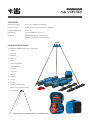
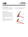
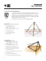
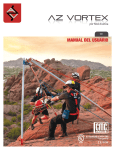
V2.2 USER’S MANUAL UL Classified to NFPA 1983 General Use 5F04 EN 795 U S E R ’ S M A N UA L INTRODUCTION Congratulations on your purchase of the AZ (Arizona) VORTEX from CMC Rescue. You have chosen the most versatile, state-ofthe-art artificial high directional (AHD) available to rescuers and industry workers today. This beautiful, handcrafted piece of equipment will serve your AHD needs for years to come. With proper study and hands-on training, you can use the AZ VORTEX in a variety of ways and in any number of environments from industry to wilderness. The AZ VORTEX is ideal for most edge transition applications including confined space entry, as well as mine, cliff and industrial rescue operations. It is also well suited for bridge and dam inspection, rope access, construction trades, military and the entertainment industry. Often called a “multipod” because of its flexibility, the two-piece head can be rigged as a standard tripod, or in advanced WHAT IS AN AZ VORTEX? In NFPA Standard 1983 terminology, the AZ VORTEX is referred to as a portable anchor device. Most riggers use the more common term artificial high directional (AHD). An AHD is used to elevate lines above edges, entryways, or obstructions in rescue operations or rope access work. Unlike other metal tripods or unequal-sided tetrahedrons, the AZ VORTEX adapts to almost any terrain or difficult set-up location. More than just a tripod, the AZ VORTEX offers three different configurations with a single unit: 1. Tripod (conventional and easel leg) 2. Bipod or A-frame (conventional and sideways) 3. Monopod or Gin Pole 2 applications such as an A-frame, sideways A-frame, or Gin Pole. The “easel” leg allows the tripod to lean, creating an easel A-frame to position the change of direction pulley closer to the edge of the cliff or the structure. With the adjustable leg lengths and the flexible third leg, the AZ VORTEX lets rescuers set up an artificial high directional in virtually any urban, industrial or wilderness location. The telescoping legs also project through the Head Set, providing a wide range of adjustment. On the A-frame and easel A-frame application, at least two pulleys can be attached directly into the Head Set without carabiners, eliminating lost head space and working clearance. This two-pulley capability makes the AZ VORTEX ideal for use with high lines and track line offsets. For rope access work, it allows the use of two Main Lines. U S E R ’ S M A N UA L SPECIFICATIONS Inside height clearance 9 ft (2.7 m) in regular tripod configuration Horizontal clearance 8 ft 9 in (2.6 m) at foot level in 9 ft height configuration Height with additional legs 12 ft (3.7 m) System weight 72 lb (33 kg) with both sets of feet Pin strength 18,000 lbf (80 kN) for the 3/8-inch leg pins 32,000 lbf (142 kN) for the 1/2-inch head pins STANDARD AZ VORTEX PACKAGE The standard AZ VORTEX package comes complete with: 1 Head Set 3 Inner Legs 7 Outer Legs 3 Raptor Feet 3 Flat Feet 1 Head Set Pulley Wheel 1 Head Set Backpack 3 Leg Bags 2 Foot Sleeves 1 Pin Bag 4 Head Pins 11 Leg Pins 15 Pin Flags 3 AZ VORTEX Hobble Straps 1 40 foot x 8 mm Cord (for tethering) 1 User’s Manual 3 For tactical purposes, AZ VORTEX hardware is also available in black. U S E R ’ S M A N UA L SELECTING FEET FOR THE AZ VORTEX The AZ VORTEX comes with two sets of feet for best performance on different types of surfaces. The performance of each foot design should be considered when setting up the AZ VORTEX. Flat Foot. This design works well on flat surfaces such as floors, roadways, or roofs. The wide surface area of the foot helps prevent penetration. Raptor Foot. Dubbed the “Raptor” because of its shape, the carbide tip penetrates the surface, helping to anchor the foot in place. The design of the leg allows the Raptor Foot to rotate to best direct the claw’s force downward, or to gain purchase on various rock features such as small holes or cracks. SURFACE Smooth An example of a smooth surface would be a concrete or asphalt roadway, metal tank cover, or roof. For most set ups, the legs may be secured by tying them together. Flat Soft Soil, Undisturbed The Raptor Feet of the AZ VORTEX are designed to penetrate into this type of substrate with minimal outward force on the A-frame legs. Use the heel of your boot on each Raptor Foot to firmly press the foot into the soil. All legs must still be independently hobbled to each other or to independent anchors. Raptor Soft Soil, Disturbed A disturbed soil condition requires additional soil pickets (not supplied) for anchoring the AZ VORTEX. The Raptor Foot on each leg should be placed up against the driven picket so that force on the AZ VORTEX forces the Claw down, not out. Secure the AZ VORTEX by lashing each individual foot to the pickets. Raptor Industrial Grating Select the desired feet depending on the type of grating. Only secure the feet to the grating IF the grating is stable and secure. 4 FOOT RECOMMENDED Dependent on grating type Roofing In conditions where the roof surface cannot be marred or punctured by the Raptor’s point, use the Flat Foot. The Flat Foot protects the roofing, but may allow a skidding action with the AZ VORTEX legs. Hobble the legs together, or secure to the roof structure or parapet. Flat Rock, Not Fractured In rock that is not fractured, use short chains looped through the Raptor Foot chain slots. Secure each side of the chain using ≥ 3/8-inch diameter expansion (Rawl) or epoxy bolts. Raptor Rock, Fractured Without placing bolts, use standard rock protection hardware to anchor the feet of the AZ VORTEX. After placing the hardware, lash the feet tightly to these anchors. Raptor U S E R ’ S M A N UA L WARNINGS When performing rescue, climbing or work within the vertical realm, the risk of injury or death cannot be eliminated. Do not use this device unless you have: • Read all the instructions and warnings. • Received competent and suitable training. • Trained your entire team on the proper use of this device. • Inspected and safety-checked the AZ VORTEX and rigging equipment before each use. • Accepted total responsibility for your safety and the equipment suitability/configuration. TRAINING AND EXPERIENCE IN TECHNICAL RIGGING IS ESSENTIAL FOR SAFE USE! This device can topple over if the user does not properly account for the direction and the strength of forces occurring in the specific situation and configuration. While the User’s Manual is not intended to teach everything necessary to safely operate this device, it is the user’s responsibility to read and understand the User’s Manual that accompanies the AZ VORTEX. It’s important at all times to follow these safety guidelines: • Always maintain a second Safety Line (Belay Line) independent of this device. • • All feet on this device must be securely anchored to resist side-ways, spreading and uplift forces. • Do not couple more than three outer leg sections together on any one leg. FIGURE 1A Inner legs flush with top of head 5 Make sure the connection pin that inserts through the head feeds through an inner leg hole when the leg is at full extension, rather than feed through the head “above” the top of the leg. When assembled correctly, the top of the leg should be flush with, or extended above the top leg sleeve of the head, Figures 1A and 1B. FIGURE 1B Inner legs extended beyond the top of head U S E R ’ S M A N UA L Proper rigging runs the Main Line through a pulley attached to the head with a head pin or through a carabiner Figure 2. This aligns the resultant force vector with the legs. • Personal Safety Lines should have anchors independent of the AZ VORTEX. Never attach or tether personnel to the AZ VORTEX itself or any of the rigging lines. • As with any equipment near the edge, always tether the equipment to prevent items from falling or being knocked over the edge. • The Main Line should never enter and exit on the same side of the AZ VORTEX head, Figure 3A. This creates a horizontal force vector that will attempt to topple the tripod. Fixing the Main Line directly to the AZ VORTEX head will cause the same hazard, Figure 3B. FIGURE 2 SAFE DANGER! UNSAFE FIGURE 3A DANGER! UNSAFE FIGURE 3B DANGER! UNSAFE VISUALIZING THE RESULTANT The resultant force vector (R) created by a Main Line under tension bisects the incoming vector (F1) and the out-going vector (F2). One way to visualize where the resultant is directed is to imagine a line drawn through the pin supporting the pulley and the pulley’s axle, extending down to the surface. F2 F1 6 R U S E R ’ S M A N UA L PRINCIPLES OF OPERATION • Stability is always a concern when using tripods, A-frames, and Gin Poles. Unless the forces are carefully evaluated, the possibility of legs slipping or the structure toppling is very real. The following Principles of Operation apply to using the AZ VORTEX as well as other tripods, Gin Poles and A-frames. • Do not exceed the safe working load. As an artificial high directional, the AZ VORTEX uses a change of direction pulley at the head. Depending on the entry and exit angle of the Main Line, the force on the legs can be multiplied to twice the weight of the load. • Whenever possible, set up the AZ VORTEX in the threelegged configuration. It usually takes less effort to transport the complete set of legs than to securely rig the AZ VORTEX in the A-frame or Gin Pole configuration. An A-frame and a Gin Pole provide options where the full tripod configuration cannot be adapted to the location. • Prevent any possible movement of the legs by connecting the feet together using Hobble Straps, cord, webbing or chain, or by anchoring each individual foot to the surface. • Consider using the easel leg to the side when setting up a sideways A-frame. If the Main Line is kept inside the legs, stability is increased. The easel leg should still be guyed back. • 8- or 9-mm Accessory Cord works well for guy lines in most circumstances. Use the triangular holes in the head for attaching guy lines. • Always run the Safety Line (Belay Line) at ground level. This minimizes the possible fall distance if the AHD topples or collapses. • Always provide travel restraint for personnel working near the edge. • • • The resultant force on any tripod should be directly down, as close to the center of the three legs as possible. When extending the easel leg of the AZ VORTEX, the resultant force vector may move toward the A-frame legs and a tag line will be necessary to stabilize the AZ VORTEX. Connect the tag line to the head and secure it to an anchor behind the AZ VORTEX. The resultant force on an A-frame should be in line with the legs. A line projected through the pin and pulley axle should be aligned with the legs. The angles between the Main Line and the legs on either side should be equal. USING THE AZ VORTEX Assembly of the AZ VORTEX Assembly of the AZ VORTEX is easiest with two or more people. Installing the AZ VORTEX at any edge without handrails requires the use of Travel Restraint within the Hazard Zone. There are two ways to assemble the AZ VORTEX: 1. Build in place. This allows easier movement but individual sections must be supported and belayed until the assembly is complete. Assemble as much as possible, such as each head piece to a leg, before moving into position. 2. Build it away from the edge and then walk it out as one unit to the edge. This may require three to four people to move it into place but only requires a single Tether Line for safety. Sometimes a combination of both ways works well, but remember that it is difficult to change pins at the head while standing on an edge by a large drop. Make these changes back from the edge and then move the AZ VORTEX into position and secure the feet only after making your final changes. Several attempts at getting 7 it right may be needed before tie down commences. This process will become less cumbersome with experience. Each method has advantages and disadvantages depending on the location and the available personnel. Practicing both will prepare the team to select the best option under difficult set up positions. Always attach a Tether Cord to the individual sections or to the entire unit until the AZ VORTEX is secured. Tether Cord(s) should be belayed on a separate anchor to prevent the AZ VORTEX from toppling over during installation. The Tether Cord(s) can be left in place during the operation for later disassembly. Never leave an unsecured AZ VORTEX unattended! Support each leg section until the unit is secured to prevent toppling during set up. As in any rigging situation, one person should be in charge of the set up and communication should be deliberate and precise. U S E R ’ S M A N UA L Anchoring the AZ VORTEX It is important to remember that the AZ VORTEX must be secured for any possible unanticipated dynamic event. This includes securing the rear easel leg for compression and tension. This leg should not be able to move forward towards the edge or back away from the edge. The most secure method to accomplish this is to anchor the rear foot to the surface as shown in Figure 4. The timing of a rescue may not allow anchoring each foot. Connecting the feet together using AZ VORTEX Hobble Straps as shown in Figure 5 is a standard practice for conventional tripods and works well with the AZ VORTEX. For NFPA-certified configurations, each pair of feet must be independently hobbled. With any tripod it is critical to keep the resultant force vector as close to the center as possible. This minimizes the horizontal vector that tends to topple the tripod. Figure 5 also shows the Main Line (blue) exiting the manhole and the pulling force positioned as close to the manhole as safety allows. This keeps the resultant force centered under the change of direction pulley. When the Main Line (red) is pulled from outside of the tripod base, the resultant force vector will try to topple the tripod, Figure 6. FIGURE 5 SAFE FIGURE 4 FIGURE 6 DANGER! UNSAFE Even with the easel leg extended, the AZ VORTEX is secure when the legs are restrained and the force vector is directed inside of the legs, Figure 7. Resultant Force FIGURE 7 8 Remember, if the AZ VORTEX is near an edge, a Tether Line is necessary to prevent the unit from accidentally falling. This is even more critical before the AZ VORTEX is loaded. U S E R ’ S M A N UA L Disassembly of the AZ VORTEX Disassembly of the AZ VORTEX is less problematic. With adequate personnel on travel restraint devices, remove the anchoring at each foot and carry the entire device back out of the hazard zone for disassembly. Again, the Tether Cord should be in place during this movement away from the edge. Once the AZ VORTEX is well away from any hazard, it may be disassembled, inspected for any damage, and stowed in its proper storage compartments. SECURING THE FRONT LEGS The front A-frame legs of the AZ VORTEX must be restrained from spreading apart, which is accomplished when the feet are anchored to the surface. If this is not possible, an alternative method is used to independently connect (or hobble) the legs together using the provided AZ VORTEX Hobble Straps, or by using independently secured accessory cords. Moderate tension should be applied so that the straps are snug but do not flex the legs. Keep the straps as low to the surface as possible to prevent tripping hazards. FLAT FOOT HOBBLE NOTE When you connect the Raptor Foot to the leg, position it so that the force exerted on the leg pushes the tip of the foot towards the center of the tripod or bipod. This encourages the “claw” to bite into the surface. RAPTOR FOOT HOBBLE 9 U S E R ’ S M A N UA L USING THE AZ VORTEX AS A TRIPOD The AZ VORTEX can be set up in a variety of tripod configurations, including an equal leg tripod. The adjustability of the AZ VORTEX allows it to fit a variety of spaces that the adjustment range of conventional, equal leg tripods may not. As discussed above, the legs should be either anchored to the surface or connected with Hobble Straps, cord, webbing or chain to keep them from spreading. This is even more important on the AZ VORTEX than the conventional tripods due to the ability of the easel leg to move. When used in the equal leg configuration, the resultant force vector should be as close to the center as possible. If not, additional rigging may be required for stability or one of the other tripod configurations may provide a more stable platform. TRIPOD SET UP WITH EXTENDED EASEL LEG One of the significant advantages of the AZ VORTEX design is the “easel” leg that allows greater flexibility than a conventional tripod. By extending the length of the easel leg, the A-frame legs can be rigged in a more vertical position. This allows the anchor points on the AZ VORTEX head to be placed closer to an edge or directly over an opening next to a wall or other barrier as shown in Figures 8 and 9. With the long easel leg, the AZ VORTEX resists the tipping force associated with equal-leg tripods, but still must be secured. The increased skidding force on the feet must be taken into account when anchoring the feet or securing the legs. FIGURE 8 FIGURE 9 10 U S E R ’ S M A N UA L USING THE AZ VORTEX AT AN EDGE Using the AZ VORTEX at an edge is a challenging set up location. This could be on a cliff, rooftop, or a tank as shown in Figure 10. Practice on low parapets first before heading to more exposed locations. Again, be sure and attach a Tether Cord to the top of the AZ VORTEX head and secure the unit before moving to an edge or using. This cord can be left in place during the operation and then used while disassembling the device. For clarity, the Tether Cord is not shown in the example. FIGURE 10 ADVANCED APPLICATIONS It is usually quicker and safer to set up the AZ VORTEX with all three legs. Bipods and monopods are inherently unstable. If you let go, the device falls over. If the resultant force does not vector straight down the legs, the guy lines take additional loading and a guy line failure will cause a collapse. For rescue teams already trained in and using improvised bipods and monopods, the AZ VORTEX follows the same principles. The AZ VORTEX is easier to transport and the set up does not require any lashing at the top. As well as attachment points for pulleys, the AZ VORTEX head provides secure points for connecting guy lines. TRAINING AND SAFETY While a tripod is inherently stable when correctly loaded, A-Frames (bipods) and Gin Poles (monopods) are inherently unstable. Adequate rigging is essential to prevent injury to subjects and rescuers. Knowledge of advanced rigging, complex guying, and establishing adequate anchors is essential. Several training organizations provide instruction on improvised high directionals. For training classes specific to the AZ VORTEX contact: CMC RESCUE SCHOOL cmcrescue.com (800) 235-5741 or (805) 562-9120 ROPES THAT RESCUE ropesthatrescue.com (928) 282-7299 11 U S E R ’ S M A N UA L A-Frame An A-frame set up requires the legs to be secured by anchoring the feet to the surface and attaching guy lines to keep the A-frame in position as shown in Figure 11. The guy lines should be under tension to eliminate movement. If the feet cannot be individually secured, the legs must be secured together. An A-frame requires guy lines connected to anchors both in the front (near or over the edge) and in the back. Additional guy lines may be needed to prevent the A-frame from moving sideways if the load should shift. To maximize the force supported by the legs and minimize the forces on the guy lines, lean the A-frame slightly towards the edge. The legs and the axle of the pulley should line up when the legs bisect the angle of the Main Line through the pulley, as shown in Figure 12. The resultant force should also be centered between the legs. This balances the forces for stability and allows the legs to take most of the load. Resultant Force FIGURE 11 Second leg is hidden from view by closer leg. Adjustable guy anchor(s) may be placed over the edge. FIGURE 12 12 U S E R ’ S M A N UA L Sideways A-Frame One of the challenges with setting up an A-frame near an edge is locating suitable anchors on the edge side. Usually the easel leg set up of the AZ VORTEX would solve this problem, but another option is a Sideways A-frame. The concerns for securing the feet remain the same. While the high anchor point is further from the edge, the anchors are located along the edge rather than over it. A Sideways A-frame set-up, Figure 13, is guyed from both sides (right and left), which alleviates the need for an anchor point close to, or over the edge as required by a conventional A-frame set-up. The head unit has two sets of holes for the pins that attach the legs. One set is angled to the side to allow better Main Line clearance. Remember that the easel leg set up of the AZ VORTEX can also be constructed as a Sideways A-frame. In such a set up, the Main Line should run inside the legs. FIGURE 13A FIGURE 13B Hobble strap is hidden from view by legs. 13 U S E R ’ S M A N UA L Gin Pole A Gin Pole or “monopod” should have a minimum of three guy lines spaced at 120˚ angles. If anchor availability permits, four guy lines spaced at 90° angles makes the set-up even more secure, Figure 14. The ground end of the pole should be secure, either anchored to the surface or placed in a natural opening or hole. As with the A-frame, the Gin Pole should be tilted so that the resultant force vector is directed down in line with the pole. ) The AZ VORTEX head has an ample number of holes for attaching the guy lines. The head should be positioned so that the Main Line clears the guy lines and does not torque the Gin Pole when the load is applied. FIGURE 14 CARE AND MAINTENANCE User Information shall be provided to the user of the product. Industry equipment standards recommend separating the user information from the equipment and retaining it in permanent record. The standard also recommends making a copy of the user information to keep with the equipment and that the information should be referred to before and after each use. Additional information regarding life-safety equipment can be found in NFPA 1500, Standard on Fire Department Occupational Safety and Health Programs, and NFPA 1983, Standard on Life Safety Rope and Equipment for Emergency Services. Inspection Inspect the AZ VORTEX according to your department’s policy for inspecting life-safety equipment. Equipment should be inspected after each use by an inspector that meets your department’s training standard for inspection of life-safety equipment. Record the date of the inspection and the results in the equipment log. Each user should be trained in equipment inspection and should do a cursory inspection before each use. Inspect the AZ VORTEX for cracks, dents, or elongation of the carabiner and pin holes. The head unit should rotate easily but not feel loose. The legs should fit together smoothly and should not appear bent or deformed. Pins should have the retaining ball present and function smoothly. If any significant damage is observed, the equipment should be removed from service. If the AZ VORTEX is dropped or impact loaded, it should be inspected by a qualified inspector prior to being returned to service. 14 In most cases, a visual inspection will not be able to determine if the equipment has been damaged. Based on the history of the incident, if there is any doubt regarding the safety of the equipment, it should be removed from service and retired. Product Lifetime. It is impossible to give a definite lifetime for life safety equipment. While carefully used gear may last a long time, one extreme or improper use could require that it be retired. Cracks, corrosion, deformation, wear, failure to properly function, major falls, any doubt as to prior usage or condition all require that the equipment be retired and destroyed. In addition to inspections before and during use, a competent person must conduct a detailed inspection every 12 months at a minimum. A record should be kept of the date, person performing the inspection and results, as well as the date of first use, name of users and any other pertinent information necessary to keep accurate track of the equipment’s usage history. Carrying, Maintenance and Storage During use, carrying, and storage, keep away from acids, alkalis, exhaust emissions, rust and strong chemicals. Do not expose to flame or high temperatures. If the equipment becomes soiled, it can be washed in soap and water. For decontamination, the equipment may be cleaned per your department’s protocols on biohazards. Make sure the parts are dry before storage and store in a dry location. Dot not store with dissimilar metals. U S E R ’ S M A N UA L REPAIR All repair work shall be performed by the manufacturer. Other work or modifications may void the warranty, and releases CMC Rescue, Inc. from all liability and responsibility. FOR INFORMATION OR SERVICE CONTACT CMC Rescue, Inc. 6740 Cortona Drive Goleta, CA 93117 USA (800) 235-5741 / (805) 562-9120 cmcrescue.com [email protected] The AZ VORTEX User’s Manual is also available to download at cmcrescue.com/azvortex. MANUFACTURED BY Rock Exotica Clearfield, Utah USA SAMPLE INSPECTION LOG The sample equipment log suggests records that should be maintained by the purchaser or user of rescue equipment. Equipment Inspection and Maintenance Log Item # Brand/Model Date Date in Service Size How Used or Maintained Comments Name MARKINGS ON THE PRODUCT The orange component of the AZ VORTEX head is marked as follows: “CE 0120 (EN 795 B)” and “WARNING: For Dangerous Situations. Risk of Death/Injury Cannot Be Eliminated. Use of this device requires specialized skills and training.” It also has the assembly date, serial number and an icon reminding users to read instructions. CE CERTIFICATION NOTIFIED BODY Conformity assessment was done by notified body No. 0120, SGS United Kingdom Limited, Unit 202B, Worle Parkway, Weston-super-Mare, Somerset, BS22 6WA, United Kingdom. Notified body controlling the manufacturing of the product: notified body No. 0120, SGS United Kingdom Limited, Unit 202B, Worle Parkway, Weston-super-Mare, Somerset, BS22 6WA, United Kingdom. COUNTRY OF ORIGIN The AZ VORTEX is made in the USA of domestic and foreign materials. The AZ VORTEX design is patented. 15 U S E R ’ S M A N UA L AZ VORTEX NFPA CERTIFIED CONFIGURATIONS THIS PORTABLE ANCHOR DEVICE MEETS THE AUXILIARY EQUIPMENT REQUIREMENTS OF NFPA 1983, STANDARD ON LIFE SAFETY ROPE AND EQUIPMENT FOR EMERGENCY SERVICES, 2012 EDITION. 5F04 EMERGENCY SERVICES AUXILIARY EQUIPMENT IN ACCORDANCE WITH NFPA 1983, 2012 EDITION. MINIMUM BREAKING STRENGTH AND RATING ARE DETERMINED AT THE CONFIGURATION OF LOWEST STRENGTH PER MANUFACTURER’S INSTRUCTIONS. RATED G (GENERAL USE), MBS 36 kN FOR THE FOLLOWING CONFIGURATIONS: CONFIGURATION 1 Tripod (all legs equal length) 1. 2 outer legs coupled to 1 inner leg at maximum length (9 ft / 2.7 m) 2. Head unit connected to the inner leg via upper head pin hole and last inner leg pin hole 3. Use either Raptor or Flat Feet 4. Legs at equal distance apart 5. Feet are required to be individually hobbled or anchored CONFIGURATION 2 Easel A-Frame 1. A-FRAME SECTION 2 outer legs coupled to 1 inner leg at maximum length (9 ft / 2.7 m) 2. EASEL LEG SECTION 3 outer legs coupled to 1 inner leg at maximum length (12 ft / 3.6 m) 3. A-frame head unit connected to the inner leg via upper head pin hole and last outer leg pin hole 4. Easel head unit connected to the inner easel leg via second-to-last leg pin hole 5. A-frame section must be at 90 degrees relative to the surface 6. Use either Raptor or Flat Feet 7. Easel leg to A-frame leg distance 10 ft (3 m) 8. Feet are required to be individually hobbled or anchored 16 Easel Tripod (raptor feet) U S E R ’ S M A N UA L GLOSSARY Artificial High Directional (AHD) An elevated change-of-direction anchor point used to change the direction of the Main Line, such as an AZ VORTEX. Fall Hazard Location with exposure to a fall. Guy Line A tensioned line that prevents the AZ VORTEX from toppling. Hazard Zone Location in which a fall hazard exits, usually considered as 6 ft (2 m) from any edge. Hobbles or Hobble Straps Used to connect the legs of the AZ VORTEX together to prevent the tripod or bipod legs from spreading or moving apart from one another. Main Line or Working Line The line used to move the load. NFPA National Fire Protection Association Resultant Force The linear direction of the sum of all of the vector forces acting on the component. Safety Line or Belay Line A second rope system used to support the load should the Main Line fail. Tether Line An 8- or 9-mm Accessory Cord used to prevent sections of the AZ VORTEX from falling over the edge. Travel Restraint Lanyard, tether or safety line device that prevents the user from reaching the edge. CMC Rescue, Inc. 6740 Cortona Drive Goleta, CA 93117 USA (800) 235-5741 / (805) 562-9120 cmcrescue.com [email protected] The AZ VORTEX User’s Manual is also available to download at cmcrescue.com/azvortex. ©2013 CMC Rescue, Inc. All rights reserved. 727300.00.120513 17