1
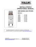
MA-9OOOAH
Portable
Air Conditioner
-
Cooling
Heating
Dehumidifying
Fan
Please read Owner's Manual
carefully before operating the
unit.
TABLE
OF CONTENTS
INTRODUCTION ...........................................................................................................................................
3
IMPORTANT SAFEGUARDS .......................................................................................................................
3
PACKAGE
CONTENTS ................................................................................................................................
4
IDENTIFYING THE PARTS ..........................................................................................................................
4
ASSEMBLY
6
REQUIREMENTS
...........................................................................................................
CONTROL PANEL AND LCD DISPLAY .....................................................................................................
7
CONTROL PANEL FUNCTIONS .................................................................................................................
8
OPERATION USING CONTROL PANEL ....................................................................................................
9
OPERATION USING REMOTE CONTROLLER
CONDENSATE
........................................................................................
WATER DRAINAGE .........................................................................................................
11
14
MAINTENANCE ..........................................................................................................................................
16
TROUBLESHOOTING
17
................................................................................................................................
TECHNICALSPEClFICATIONS
.................................................................................................................
18
DISCLAIMER ..............................................................................................................................................
18
CONTACT INFORMATION
18
WARRANTY
........................................................................................................................
...............................................................................................................................................
19
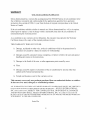
INTRODUCTION
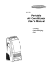
Thank you for purchasing the Soleus Air MA-9000AH portable air conditioner.
This unit is
designed to improve living and working comfort by providing cooling, dehumidifying
and fan
functions with only minimum installation required. With its whisper quite operation and attractive
design, you will enjoy the convenience and comfort that this unit provides for many years to come.
When operating as an air conditioner, this unit is designed for spot cooling or cooling
no larger than 300 square feet with a standard ceiling height of 8 feet.
IMPORTANT
Before
installing
for a room
SAFEGUARDS
and using
the portable
air conditioner,
please
read
this Owner's
manual
carefully.
1. Never use or store gasoline or other flammable
2.
.
4.
.
.
7.
Maintain at least 10" (25cm) clearance
air inlet or outlet grilles.
vapor or liquid near this unit.
space around all side of the unit. Do not obstruct
All in-home wiring must comply with local and national codes and be installed by a
qualified technician. The power supply must be properly grounded.
All wiring problems
should be resolved by a qualified technician BEFORE installation and use of this air
conditioner
Always inspect the power cord and plug for signs of damage before use.
For your safety, this unit is grounded through the power cord plug when connected
matching wall outlet. Do not use an adapter plug or extension cord.
When removing the power cord from the wall outlet, always grasp the plug firmly and pull
straight from the outlet. Never unplug the air conditioner by pulling on the cord itself.
Do not use the unit in the immediate surroundings of a bath, a shower or a swimming pool.
Never immerse the unit in water or any other liquid.
8. Keep out of reach of children.
9.
to a
Use product only as directed in this manual; unintended
use may void the warranty.
PACKAGE
CONTAINS:
1 Portable Air Conditioner
1 Air Exhaust Duct
1 Window Kit (2 Sliding Panels)
1 Window Kit Adapter
1 Remote Controller
2 AAA Batteries
1 User Manual
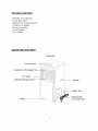
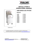
IDENTIFYING
THE PARTS
Front View
Control
Up/down
Panel
--
Air Swinging
Air Outlet
Left/right
Swinging
Handle
Water
Caster
Tank
Cable(power
Cord and Plug)
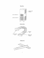
Rea.r
View
...........................
Upper Air Inlet
Grill/Filter
Hot Air Outlet Grill .............
Lower Air Inlet Grill
ItI,fJtIIIJ
i
Exhaust
Duct
E×h_ust
Duct
Window
Window Kit
Kit
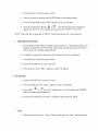
ASSEMBLY
l)
Exhaust
REQUIREMENTS
Duct
When you use the unit as an air conditioner, the hot exhaust air must be directed out of the
room. The exhaust duct is required to allow the hot air out of the room through a window.
DO NOT INSTALL OR USE THE EXHAUST DUCT WHEN THE U_NIT IS
OPERATED AS A DEHUMIDIFIER
OR FAN.
Slide "Unit Terminal
End" of the exhaust
connector completely over the "Hot Air Outlet
Grill" on the rear of the unit. Plastic grooves
are located on the hot air outlet help to guide
the exhaust connector into place.
Window Kit Mounting: Connect the window
kit adapter to the external end of the exhaust
duct. The exhaust duct is now ready to be
attached to the window kit. See page 7 for
window kit installation
Wall Mounting: Mount the external end of the
exhaust duct to a 5¼" hole within the wall.
Creating a hole into a wall is a separate
procedure that may require professional
installation.
NOTE: In orderto achievemaximumroomcooling efficiency,the exhaustduct should
remainasshortandstraightaspossible.To further shortenthe exhausthose,first unthread
eitherexhaustductadapterclockwiseto removeit. Thencut thehoseto desiredlength. It
is not recolmnendedto increasethe manufacturer'slengthof the exhausthose.This may
reducethecooling efficiencyor damagetheunit.
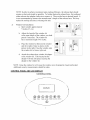
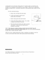
2)
Window Kit Installation
a.
b.
C.
d.
Open window approximately
5 inches (13 cm)
Adjust the length of the window kit
to the same length of the window; use both
panels if necessary. The window kit
has a maximum length 50.5 inches.
Place the window kit between the window
and the window frame as shown in the
picture to the right. Close the window onto
the window kit to form a tight seal.
Attach the exhaust duct window kit adapte
to the window kit. Tabs located on the
adapter will lock into place securing the
adapter to the window kit.
NOTE: Using the window kit will cause the window not to be properly closed and locked.
Additional security measurements should be taken.
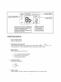
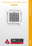
CONTROL
PANEL AND LCD DISPLAY
CONTROL
PANEL
\
DISPLAY
@ @
TIMER
TIME
TEMP+
MODE
TEMP-FAN
SPgEB
SWIt'_G
HIGHMED LOW_
SWING _'"
! OperNion,mode in_ic8tor_---
eF
HEAT
SET FAULT
D splayof preset,temperaturean_failure_de
• WhenSETis,displayed medisplayeddigits
indicate_'_edes led tempe[ature,
• WhenFAULTisdisplayed,_e dispi_d digiLs
indicatethecode of fNures.
Control
.
.
Panel Functions
Power On/Off Control
Starts or stops the unit
Temperature Settin_ Control
Select the desired temperature
recommended
.
.
setting by pressing either the it_
to set the temperature
Mode Control
Select the functions
a.
b.
c.
.
[ Displayo_Time Se_,ting
1
I ThedisNayeddigits
i_dicatelhe remainin#
_me of onlo# ope[aiion
before selecting
or _
the Mode Control.
of the unit for:
Air Conditioning Mode (COOL)
Dehumidifying Mode (DRY)
Heating Mode (HEAT)
Fan Speed Control
Select the fan speed for:
a.
b.
High
Medium
C.
Low
Timer + Time
Sets the amount of time, in hours, to automatically
start or to stop the unit
key. It is
When the unit is On, press "Tilner" Button, then press the "Tilne" button until the
desired number of hours is displayed in the lower right corner of the display
window. The unit will automatically power Off once the selected number of hours
has elapsed.
a.
When the unit is Off, press "Tilner" Button, then press the "Time" button until the
desired number of hours is displayed in the lower right corner of the display
window. The unit will automatically power On once the selected number of hours
has elapsed.
b.
NOTE: The timer function must be manually reset before each automatic
6.
Swing
Activates
Operation
or deactivates
the oscillating
Usinq the Control
start or stop.
louvers
Panel
1. Cooling Operation
a.
Be sure that the drain bucket is properly placed in the unit. If the drain bucket is not
properly secured, the red "Water Full" light located on the front panel will blink
and the unit will not begin cooling.
b.
Be sure the exhaust duct properly
installation.
c.
Plug the Power Cord to the power outlet.
d.
Turn on the unit by pressing
installed.
Refer to page 6 for exhaust duct
the On/Off Button on the control panel.
e. Press the Mode Button until "COOL" appears on the LCD display.
Press the Temperature Button A or _ until the desired room
temperature appears on the LCD. The temperature ranges from
63°F-88°F (17°C-3 I°C). After two seconds the current room
temperature will appear on the LCD screen
NOTE: During hot days, the unit will cool off the room most efficiently by setting the
telnperamre to the lowest setting and the Pan speed to the highest setting (see page 9 for fan
operation). Reducing the length of the exhaust duct, insulating the exhaust duct and keeping
direct sunlight to a minimum will also improve the cooling efficiency.
2. Dehumidifying Operation
a.
Be sure that the drain bucket is properly placed in the unit. If the drain bucket is not
properly secured in the unit, the red "Water Full" light located on the front panel
will blink and the unit will not begin dehumidifying.
b.
If exhaust duct is attached,
c.
Plug the Power Cord to the power outlet.
d.
Turn on the unit by pressing
e.
Press the Mode Button until "DRY" appears on the LCD display.
remove
it from the rear of the air conditioner
the On/Off Button on the control panel.
NOTE: Do not use the exhaust duct when the unit is running at dehumidifying mode. You must
remove the exhaust duct from the unit. When the unit is running at dehumidifying mode, the tan
speed cannot be adjusted. Keep the windows and the doors closed to aid the efficiency of the unit
in removing the moisture from the room.
3.
Fan Operation
a.
Plug the Power Cord to the power outlet.
b.
Turn on the unit by pressing
c.
Press the Mode Button until "COOL"
d.
or _ to set the temperature HIGHER than
Press the Temperature Button
the current room temperature.
After two seconds the current room temperature
will appear on the LCD screen.
the On/Off Button on the control panel.
appears on the LCD display.
Set the fan speed to "LOW" "MEDIUM" or "HIGH" by pressing the Fan Speed
button.
4.
Heating Operation
a.
Plug the Power Cord to the power outlet.
b.
Turn on the unit by pressing
c.
Press the Mode Button until "Heat" appears on the LCD display.
d.
Press the Temperature Buttoni_
(x_ 7
until the desired room temperature
appears on the LCD. The temperature ranges from 63°F-88°F (17°C-3 I°C).
NOTE: When the unit is operating
the On/Off Button on the control panel.
in heating mode, the exhaust duct is not required.
10
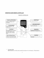
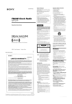
OPERATION
USING REMOTE
CONTROLLER
REMOTE
I
CONTROLLER
Sets the _an sp_e_ t_ H_gh,
F;_n
Speed Bu_on
m_diwm
or
_ow
Timer 8ut_o,n
Swing Bu_on
P_es_ _NSbu_or_acHvates or
deactivates the oscillating}ouvers
.:S,r_s
th_ _mo unt o f tirr_, in h#_rs,
to _u{o matio_R_ystart or sto# th_
an _; Press "HOUR" butto _ _#
select the #_mber of desired
ho_rs
1
Bour _nd MinuSe Buttons
Sets the current tim_ and number
of hours for _u_o,sta_
and stop
1. To Set the Clock
Open the back cover of the remote controller
11
and insert two AAA batteries.
When batteries
are installed or replaced,
time:
the clock is set to 12:00AM.
.......
To set present
¸¸¸¸¸¸¸%¸
n
----_
Press
the HOUR
Press
the
huron
MiN bu_on
to Select the hour
to Select
the minute
I Press the CLK botton again,then
H,,e
b,Ck
oo er.
reattach
2. Cooling Operation
Be sure that the drain bucket is properly placed in the unit. If the drain bucket is not
properly secured, the red "Water Full" light located on the front panel will blink
and the unit will not begin cooling.
b.
Be sure the exhaust duct properly installed. Refer to page 6 for exhaust duct
installation.
c. Plug the Power Cord to the power outlet.
d. Press the ON/OFF key to turn on the unit
e. Press the Mode key until the LCD displays "COOL"
f.
Press either _+\, of _
desired temperature
key of the Temperature keyuntil the LCD displays the
g. Press the Fan Speed key until the LCD displays the desired Pan speed.
3. Heating Operation
12
a.
Plug the Power Cord to the power outlet.
b.
Turn on the unit by pressing
c.
Press the Mode Button until "Heat" appears on the LCD display.
d.
Press the Temperature Button /_
ot_
until the desired room temperature
appears on the LCD. The temperature ranges from 63°F-88°F (17°C-3 I°C).
NOTE: When the unit is operating
.
the On/Off Button on the remote control.
in "HEAT"
mode, the exhaust duct is not required.
Dehumidifying Operation
a. Be sure that the drain bucket is properly placed in the unit. If the drain bucket is not
properly secured, the red "Water Full" light located on the front panel will blink
and the unit will not begin dehumidifying.
b. If attached, remove the exhaust duct from the back of the air conditioner
c. Plug the Power Cord to the power outlet.
d. Press the ON/OFF key to turn on the unit
e. Press Mode key until "DRY" appears on the LCD display.
.
Fan Operation
a. Press the ON/OFF key to turn on the unit
b. Press the Mode key unit "COOL" appears on the LCD display.
c. Press either
_
or _
key of the temperature to set the temperature HIGHER
than the current room temperature.
d. Press the Fan Speed key until the LCD displays the desired Pan speed.
.
Timer
a.
When the unit is On, press "Timer" Button, then press the "Hour" button until the
13
desired number of hours is displayed in the LCD. The unit will automatically
Off once the selected number of hours has elapsed.
b.
When the unit is Off, press "Timer" Button, then press the "Hour" button until the
desired number of hours is displayed in the LCD. The unit will automatically power
On once the selected number of hours has elapsed.
NOTE: The timer function must be manually reset before each automatic
CONDENSATE
1)
power
WATER
start or stop.
DRAINAGE
Internal Water Bucket
When operating in cooling or dehumidifying
mode, the condensate water will drain into
the internal water bucket. Depending o17the surrounding humidity, the unit can
continuously operate for 2 to 12 hours before the internal water bucket is full. When the
internal water bucket becomes full, the red "Water Full" light located on the front of the
unit will flash. The compressor will stop, but the Fan will continue to run at the set speed.
To empty the water bucket:
a.
Turn the unit off.
b.
Remove water bucket slowly and discard
the water inside the bucket.
c.
Place the bucket back to its original position
d.
Turn the unit on
*The drain bucket may be emptied before it is full. First turn off the unit, then wait
3 minutes before removing the water bucket to prevent the condensate water from
discharging into the unit.
NOTE: If you remove the water bucket while the unit is operating in cooling or dehumidifying
mode the red "Water Full" Light will flash and the compressor will stop. Once the drain bucket is
placed back in the unit, the compressor will remain off for approximately 3 minutes before
restarting the cooling or dehumidifying
cycle.
2)
Continuous Drainage
The unit can operate on continuous drainage mode. When the unit is operating on continuous
drainage mode, condensate water will not drain into the internal water bucket. Condensate water
14
is discharged by gravity through a drainage tube (12" length) to either an external hose (not
included) or to a condensate water pump device (not included). When the unit is operating on
continuous drainage mode, it can operate continuously without periodic stops to empty the water
bucket.
To allow continuous
a.
b.
C.
d.
e.
NOTE:
to carpet,
Remove the water bucket from the cabinet.
Find the tube hanging beside the water
bucket inside of the cabinet.
Remove the plug from the end of the tube.
Connect the drainage tubing to a hose.
or adapter (not provided) if necessary
Use a clamp
Place the other end of the hose into either an external
water bucket, a floor drain or the intake side of a
condensate water pump.
When
automatically
drainage:
using
when
floors,
the continuous
an external
furniture
drainage
water
and other
bucket
method,
is full.
the
unit will NOT
Spill water
can cause
shut
off
substantial
damages
valuables.
NOTE: Do not use a lengthy drainage hose without a condensate water pump as water may
overflow into the internal drain bucket which requires periodic manual drainage
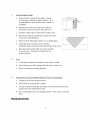
MAINTENANCE
Note: Before performing any maintenance
the power plug from the power outlet.
activities turn the unit off and remove
15
1)
Clean or Replace Filter
a.
2)
3)
If the air filter is clogged, the airflow volume
will decrease, reducing cooling efficiency. It is
recolmnended to clean the filter once a month or
as needed.
b.
Push down the tab on the filter cover and pull
outwards to remove the entire filter and cover.
c.
Carefully
d.
Wash the air filter by immersing
water with a mild detergent.
e.
Rinse the filter thoroughly
f.
Attach the filter to the filter cover with the
attachment hooks located on the inside surface of the cover
g.
Place the bottom of the filter cover into the holes
in the unit case. Push the cover back into its
original position.
remove the air filter from the filter cover.
it gently into warm
(,4_)2
and dry it in a shaded place.
;Y;hg//
i fll¢/y_
Case
a.
Avoid direct exposure to sunlight as case color may fade.
b.
Clean surface area with a damp cloth. Dry with a soft towel.
c.
Do not use abrasive cleaning products.
Storing the Unit for an Extended
Period of Time or Transporting
a.
Unplug the unit from the power outlet.
b.
Ensure that the water bucket is empty.
c.
If using continuous drainage, disconnect
cap the end of the internal drain robe.
d.
Store and transport unit in an upright position.
place.
TROUBLESHOOTING
16
any external drain hose and
Store unit in a cool dry
0
PROBLEM
POSSIBLE
Unit does not operate
CAUSE
Unit is unplugged
Securely plug receptacle
the power outlet
Drain bucket is full
Empty water bucket
Water bucket not installed
Completely
correctly
Air exhaust is clogged
Timer is on
Unit does not cool room
REMEDY
There is a heating source in the
room
Temperature
setting is too high
Air filter is dirty
Air exhaust is not installed
correctly
into
insert water bucket
Remove obstruction from
exhaust hose
Cancel the timer
Turn down or off the other
heating source
Lower temperature
setting
Clean or replace the air filter
Check the exhaust duct to
make sure that the hot exhaust
air is being vented out of the
room
Room is too big or too much
ambient sunlight is reaching in
There is frost on the evaporator
This unit provides spot cooling
or cooling tbr a room no larger
than 300 square feet with
standard ceiling height
The unit will defrost
In dehumidifying mode, no
cool air coming out
There is frost on the evaporator
automatically
and return to
operation afterwards
The unit will defrost
"Water Full" indicator is
blinking
The water bucket is full
The water bucket is not
Noise or vibration
installed correctly
Surt:ace is not level
automatically and will return to
operation afterwards
Empty the water bucket
Completely insert the water
bucket
Place unit on a level surt:ace
Water is leaking from unit
Surface is not level
and away from obstructions
Place unit on a level surt:ace
Drainage
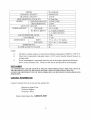
TECHNICAL
plug is loose
SPECIFICATIONS
17
Make drain tube is properly
secured and plugged
MODEL
COOLING CAPACITY
MA-9000AH
HEATING
ll00
9000 BTU/hr
CAPACITY
DEHUMIDIFYING
CAPACITY
POWER
COOLING/HEATING
88 Pints/Day
1120W/1350W
DEHUMIDIFYING
AIR FLOW VOLUME
POWER
SOURCE
W
1100W
180 CFM
VOLTAGE
115 V 60 HZ
RATED CURRENT
11.5 AMP COOLING
11.7 AMP HEATING
54 db
77 Lbs
SOUND PRESSURE LEVEL
NET WEIGHT
DIMENSIONS
BODY
17'/4 x 143/4x 32'/2 Inches
PACKAGE
26'/2 x 18'/2 x 34'/2 Inches
R22
4L
REFRIGERANT
WATER BUCKET VOLUME
NOTE:
1)
2)
The above cooling capacity is measured at ambient temperature of DB 86 F, WB 78 F.
Noise level is measured at the point where is 3.28 ft away from the front of the unit, in
cooling mode.
Power consumption is measured when fan runs at the highest speed Specifications
above are for reference only. Please see the actual data printed on the nameplate.
3)
DISCLAIMER
ALL INFORMATION
AND THE TECHNICAL
SPECIFICATIONS
PRESENTED
IN THL_ USER'S MANUAL
ARE THE PRESENTATION
OF THE MANUFACTURER.
SOLEUS INTERNATIONAL
HAS NOT
CONDUCTED
INDEPENDENT
TEST OF THE INFORMATION
AND THE SPECIFICATIONS
PRESENTED
HERE WITHIN.
CONTACT
INFORMATION
Contact Customer
Service at our tool free number for:
Optional or Spare Parts
Technical Support
Warranty Claims
Soleus International Inc. 1.888.876.5387
18
WARRANTY
ONE YEAR
LIMITED
WARRANTY
Soleus International Inc. warrants the accompanying MA-9000AH Soleus Air air conditioner to be
free of defects in material and workmanship for the applications specified in its operation
instruction for a period of ONE (1) year from the date of original retail purchase in the United
States or Canada.
If the air conditioner exhibits a defect in normal use, Soleus International Inc. will, at its option,
either repair or replace it, free of charge within a reasonable time after the air conditioner is
returned during the warranty period.
As a condition to any warranty service obligation, the consumer
Certificate along with a copy of the original purchase invoice.
THIS
l)
WARRANTY
DOES
NOT
COVER:
Damage, accidental or other wise, to the air conditioner while in the possession
consumer not caused by a defect in material or workmanship.
2) Damage caused by consumer misuse, tampering,
handling provisions in the instructions.
of a
or failure to follow the care and special
3) Damage to the finish of the case, or other appearance
4)
must present this Warranty
parts caused by wear.
Filter.
5) Damage caused by repairs or alterations
authorized by Soleus International Inc.
6) Freight and Insurance
of the air conditioner
cost for the warranty
by anyone other than
service.
This warranty covers only new products purchased from our authorized
It does not cover used, salvaged, or refurbished
products.
dealers or retailers.
ALL WARRANTIES, INCLUDING ANY IMPLIED WARRANTY OR MERCHANTABILITY ARE LIMITED TO
ONE-YEAR DURATION OF THIS EXPRESS LIMITED WARRANTY. SOLEUS INTERNATIONAL
INC. DISCLAIMS ANY LIABILITY FOR CONSEQUENTIAL
AND 1N NO EVENT SHALL SOLEUS INTERNATIONAL
OR INCIDENTAL DAMAGES
1NC.'S LIABILITY EXCEED THE
RETAIL VALUE OF THE AIR CONDITIONER FOR BREACH OF ANY WRITTEN OR IMPLIED WARRANTY
WITH RESPECT TO THIS AIR CONDITIONER
Serial No
19