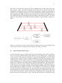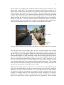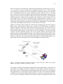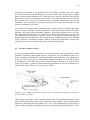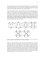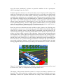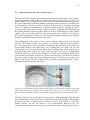
1
AALTO UNIVERSITY
School of Electrical Engineering
Department of Electronics
Jussi Kuutti
A Test Setup for Comparison of People Flow Sensors
Licentiate’s Thesis submitted in partial fulfillment of the requirements for the
degree of Licentiate of Science in Technology in Espoo 23.3.2012
Supervisor:
Professor Raimo Sepponen
Second examiner:
Professor Petri Vuorimaa
Instructor:
Lic.Sc.(Tech.) Matti Linnavuo
AALTO-UNIVERSITY
SCHOOL OF ELECTRICAL ENGINEERING
ABSTRACT OF THE
LICENTIATE'S THESIS
Author:
Jussi Kuutti
Title of thesis:
A Test Setup for Comparison of People Flow Sensors
Date:
23.3.2012
Pages:
10 + 89
Chair:
Applied electronics
Chair code:
S-66
Supervisor:
Professor Raimo Sepponen
Second examiner:
Professor Petri Vuorimaa
Instructor:
Lic.Sc.(Tech.) Matti Linnavuo
People flow sensor is a device used to measure the number and often also the direction of people passing through a certain passage per unit time. Sensors based on a variety of technologies are available
including infrared beam sensors, and video and infrared camera sensors. The applications of people
flow sensors include gathering counting data for customer flow modeling, demand based ventilation
control, and safety applications. The quality and further feasibility of the collected sensor data are
subject to the accuracy and reliability of the sensor used. That is why the proper sensor for a desired
application has to be chosen. Efficient state-of-the-art sensors are needed in busy locations but are
usually expensive and often require stable environmental conditions. Simpler, budget-priced sensors
cannot handle complex situations but are generally more robust in tolerance to diverse ambient conditions.
The aim of this thesis is to design and realize a test setup that can be used to compare nine people flow
sensors based on different technologies and to collect test data by exploiting an existing setup. Additionally, the literature is reviewed for previous research on people flow sensors and their applications.
Eight of the selected test sensors provided either one or two pulse-channel outputs, depending on their
direction sensitivity. The data collection was implemented using data loggers connected to a commercial server through a public GSM network. The basic resolution of the GSM loggers was one hour, but
six-minute data was available for closer analysis. An exception was one video camera sensor that was
connected to a local PC via an Ethernet connection and provided counting data with a resolution of 15minutes.
A suitable doorway for a sensor test site was selected at the Aalto Design Factory. Sensors were
mounted on the doorposts, wall, ceiling, or fixed to the floor according to the manufacturers’ recommendations. The operation of the sensors was verified and found out to work properly. There were,
however, certain drawbacks with the test setup: all the sensors could not be installed on the same
counting line and the limited mounting height for the camera sensors. The completed test setup was
used to collect sensor data for about 30 days together with five separate one-hour manual on-site control counting sessions including simultaneous live video capture. Related future work will include the
analysis of the collected sensor test data and the utilization of suitable sensors in building applications.
Keywords:
People flow rate, people flow sensor, visitor counter, sensor comparison,
demand controlled ventilation
AALTO-YLIOPISTO
SÄHKÖTEKNIIKAN KORKEAKOULU
LISENSIAATTITYÖN
TIIVISTELMÄ
Tekijä:
Jussi Kuutti
Työn nimi:
Testijärjestely ihmisvirtasensorien vertailua varten
Päivämäärä:
23.3.2012
Sivumäärä:
10 + 89
Professuuri:
Sovellettu elektroniikka
Koodi:
S-66
Työn valvoja:
Professori Raimo Sepponen
Toinen tarkastaja:
Professori Petri Vuorimaa
Työn ohjaaja:
TkL Matti Linnavuo
Ihmisvirtasensorilla voidaan mitata valitun väylän läpi tietyssä ajassa kulkevien ihmisten määrää. Sensoreita on saatavilla useisiin eri mittausmenetelmiin perustuen, mm. infrapunavalokennosensoreita
sekä video- ja infrapunakamerasensoreita. Ihmisvirtasensorisovelluksiin kuuluvat mm. laskentadatan
kerääminen asiakasvirtamallinnuksia varten, tarpeeseen perustuva ilmanvaihdon hallinta sekä turvasovellukset. Kerätyn sensoridatan laatu ja edelleen sen käyttökelpoisuus ovat riippuvaisia käytetyn sensorin tarkkuudesta ja luotettavuudesta. Näin ollen haluttuun sovellukseen on tärkeää valita sopivin sensori. Viimeisintä tekniikkaa edustavat suorituskykyisimmät laitteet soveltuvat vilkkaisiin mittauskohteisiin, mutta ovat kuitenkin yleensä kalliita ja edellyttävät usein vakaita ympäristöolosuhteita. Yksinkertaisemmat ja halvemmat sensorit eivät selviydy monimutkaisista tilanteista, mutta ovat yleensä ottaen
sietokykyisempiä erilaisia ympäristöolosuhteita kohtaan.
Tämän lisensiaattityön päämääränä oli suunnitella ja toteuttaa testijärjestely yhdeksän, eri tekniikoihin
perustuvan ihmisvirtasensorin vertailua varten sekä kerätä testimittausdataa valmista järjestelyä käyttäen. Lisäksi tarkoituksena oli tehdä katsaus ihmisvirtasensoreiden ja niiden sovellusten aikaisempaan
tutkimukseen. Kahdeksan testisensorin ulostulona oli niiden suunnantunnistuskyvystä riippuen yhdestä
kahteen pulssikanavaa. Datankeräys toteutettiin yleiseen GSM-verkkoon liitetyillä dataloggereilla.
GSM-loggereiden perusresoluutio oli yksi tunti, mutta kuuden minuutin mittausdataa oli saatavilla
tarkempia analyyseja varten. Poikkeuksen muodosti yksi kamerasensoreista, joka oli yhdistetty PCtietokoneeseen lähiverkon kautta ja tarjosi mittausdataa 15-minuutin resoluutiolla.
Testipaikaksi sopiva kulkuväylä valittiin Aalto Design Factorylta. Sensorit kiinnitettiin ovenpieliin,
seiniin, kattoon tai lattiaan valmistajien suositukset huomioon ottaen. Koekäyttöjen perusteella sensorit
toimivat asianmukaisesti, mutta testijärjestelyssä havaittiin kuitenkin puutteita: mm. kaikkia sensoreita
ei voitu asentaa täsmälleen samalle laskentalinjalle ja kamerasensorien asennuskorkeus oli rajoitettu.
Valmista testijärjestelyä käyttäen kerättiin sensoridataa noin 30 vuorokauden ajan. Lisäksi tehtiin reaaliaikaista manuaalista kontrollimittausta viitenä erillisenä yhden tunnin ajanjaksona samanaikaisen
videokaappauksen kanssa. Aiheeseen liittyvä jatkotutkimus tulee sisältämään mm. tässä työssä kerätyn
sensoritestidatan analysointia sekä sopivien sensorien hyödyntämistä taloteknisissä sovelluksissa.
Avainsanat:
Ihmisvirta, ihmisvirtasensori, kävijälaskuri, sensorivertailu,
tarpeeseen perustuva ilmanvaihdon hallinta
IV
Acknowledgements
This licentiate’s thesis was completed at the Aalto University Department of Electronics
as a part of the 4D-Space project of the university’s Multidisciplinary Institute of Digitalisation and Energy (MIDE) research program. I would like to thank the MIDE program for financially supporting the project and further my thesis. Professor Raimo
Sepponen supervised my thesis work reviewing and commenting the ready thesis, for
which I wish to express my gratitude. Likewise I’d like to thank professor Petri Vuorimaa for acting as a second examiner for the thesis. Laboratory manager Matti Linnavuo, who acted as an instructor for the thesis work, I’d like to thank for his valuable
improvement suggestions for the thesis contents. Thanks go also to university teacher
Luis Costa, who proof-red the complete manuscript.
Teknovisio Ltd. provided the vast majority of the test sensors and the data collection
equipment to my usage for which I’m appreciative. Special thanks go to Teknovisio’s
project manager Rauli Laiho with whom the test setup described in this thesis was
planned and completed in co-operation. I also want to express my gratitude to all my
fellow-researchers at the MIDE 4D-Space project. Special thanks go to James Culley,
Riikka Hänninen and Sonja Lätti for their valuable assistance in performing the definitely tedious manual control counting. The Aalto Design Factory staff receives my
thanks for co-operation, especially the Factory’s machine shop for preparing the sensor
mounting equipment needed in the test setup. Thanks belong also to all my colleagues at
the Department of Electronics who have in any possible way contributed to this research
work.
Further I’d like to thank my friends and relatives for every cheerful moment that directly or in-directly has sustained me. I’m especially grateful to my mother Leena and my
in-laws-to-be Helka and Seppo for their continuous support during my graduate studies.
Finally, I’d like to express my deepest gratitude to my fiancée Silke whose love and
support made the completion of this thesis work possible.
Otaniemi, 23.3.2012
Jussi Kuutti
V
Contents
ACKNOWLEDGEMENTS ........................................................................................ IV
CONTENTS ....................................................................................................................V
SYMBOLS AND ABBREVIATIONS ..................................................................... VII
1 INTRODUCTION .......................................................................................................1
1.1
BACKGROUND AND THESIS OBJECTIVES ...................................................................................... 1
1.2
MIDE 4D-SPACE PROJECT.......................................................................................................... 2
1.3
PEOPLE FLOW RATE AND PEOPLE FLOW SENSOR ......................................................................... 3
1.4
STRUCTURE OF THE THESIS ......................................................................................................... 4
2 PREVIOUS RESEARCH ON PEOPLE FLOW SENSORS ................................5
2.1
SENSOR TYPES ............................................................................................................................ 5
2.2
INFRARED LIGHT BEAM SENSORS ................................................................................................ 8
2.3
ACTIVE INFRARED SENSOR ARRAYS............................................................................................ 9
2.4
PASSIVE INFRARED SENSORS .................................................................................................... 10
2.5
PRESSURE SENSITIVE SENSORS ................................................................................................. 16
2.6
VIDEO AND INFRARED CAMERA SENSORS ................................................................................. 18
2.7
ULTRASOUND SENSORS ............................................................................................................ 22
2.8
SENSOR CALIBRATIONS ............................................................................................................ 25
2.9
SENSOR REVIEWS ...................................................................................................................... 27
2.10
SENSOR COMPARISON TESTS ..................................................................................................... 30
3 APPLICATIONS FOR PEOPLE FLOW SENSORS ..........................................40
3.1
VISITOR COUNTING AND RETAIL APPLICATIONS ........................................................................ 40
3.2
DEMAND CONTROLLED VENTILATION ....................................................................................... 43
3.3
SAFETY APPLICATIONS ............................................................................................................. 48
4 SENSORS OF THE TEST SETUP .........................................................................50
4.1
TECHNICAL DETAILS OF THE TEST SENSORS .............................................................................. 50
4.2
PRESSURE SENSITIVE SENSOR MATS .......................................................................................... 51
VI
4.3
INFRARED LIGHT BEAM SENSORS .............................................................................................. 53
4.4
INFRARED CAMERA AND VIDEO CAMERA SENSORS ................................................................... 55
5 SETUP FOR SENSOR COMPARISON TESTS ..................................................59
5.1
TEST SITE LOCATION ................................................................................................................. 59
5.2
SENSOR ASSEMBLY ................................................................................................................... 59
5.3
DATA LOGGING ......................................................................................................................... 68
5.4
SENSOR CONFIGURATION .......................................................................................................... 72
6 SENSOR TEST DATA COLLECTION ................................................................75
6.1
ON THE DATA COLLECTION ....................................................................................................... 75
6.2
COUNTING REPORTS ................................................................................................................. 76
6.3
PRECISION TEST DATA .............................................................................................................. 78
7 CONCLUSIONS AND FUTURE WORK .............................................................79
7.1
CONCLUSIONS .......................................................................................................................... 79
7.2
FUTURE WORK .......................................................................................................................... 82
BIBLIOGRAPHY .........................................................................................................83
VII
Symbols and abbreviations
Symbols
C
Sensor counting result
1/s
Ccal
Calibrated sensor counting result
1/s
c
Indoor air carbon dioxide
concentration
ppmv
cs
Supply air carbon dioxide
concentration
ppmv
cf
Calibration factor
-
G
Carbon dioxide generation
rate per person
h
Height
m
M
Manual counting result
1/s
N
Number of people
-
Qs
Supply air ventilation rate
q
People flow rate
1/s
t
Time
s
v
Mean speed of people
m/s
w
Width
m
wo
Width of the optimal counting area
m
Interval delimiter
-
Hourly counting error rate
%
Average counting error rate
%
Mean people density
1/m2
ave
/min
/min
VIII
Abbreviations
Aalto ELEC
Aalto University School of Electrical Engineering
Aalto ENG
Aalto University School of Engineering
Aalto ECON
Aalto University School of Economics
Aalto SCI
Aalto University School of Science
Aalto ARTS
Aalto University School of Art, Design and Architecture
Al
Aluminum
ANN
Artificial neural network
APeC
Automated People Counting from Video
ASHRAE
American Society of Heating, Refrigerating and
Air-Conditioning Engineers
AVI
Audio video interleave
CAV
Constant air volume
CCTV
Closed-circuit television
CO2
Carbon dioxide
CSV
Comma-separated values
C++
One of the popular general-purpose programming languages
DC
Direct current
DCV
Demand controlled ventilation
ESN
Echo state network
EUR
Euro (currency)
GSM
Global system for mobile communications
GUI
Graphical user interface
HSI
Hue, saturation, and intensity
Hz
Hertz
IAQ
Indoor air quality
IX
IR
Infrared
ITS
Intelligent transportation system
kg
Kilogram
LVQ
Learning vector quantization
lx
lux
m
Meter
MICA
Multidimensional independent component analysis
MIDE
Multidisciplinary Institute of Digitalisation and Energy
MOCUS
Moving Object Counting approach using
Ultrasound Sensor networks
N/A
Not available
PbTiO3
Lead titanate (lead titanium oxide)
PC
Personal computer
PET
Polyethylene terephthalate
PIR
Passive infrared (sensor)
PoE
Power over Ethernet
ppmv
Parts per million in a volume
RBF
Radial basis function
RJ
Registered jack
SIM
Subscriber identity module
SOM_PAK
Self-organizing map program package
SVGA
Super video graphics array
USA
United States of America
USB
Universal serial bus
USD
United States dollar
UK
United Kingdom
X
V
Volt
W
Watt
VGA
Visibility graph analysis
VHS
Video Home System
XML
Extensible markup language
°C
Centigrade, degree Celsius
1
1
1.1
Introduction
Background and thesis objectives
People flow measurement is a valuable tool in various applications, e.g. in mapping
market strategies (Adriano et al. 2005). For instance, at shopping malls one of the most
important attributes determining the value of individual stores is the number of people
passing it by. In fact the success or failure of a shopping center as well as the stores
wherein is ultimately determined by the circulation of shoppers (Brown 1991). With
better information about the shopper circulation through customer flow measurement
the shopping mall administration can define more accurately correct rental levels for
individual tenants. Knowledge about the actual distribution of flows inside the shopping
center is also beneficial for the tenants and gives them information about the influence
of mutual placing of the shops and stores. Providing customers a comfortable and cozy
shopping environment hence is beneficial for the mall proprietors.
Knowledge of the people flow sensor performance is of paramount importance. The
more reliable data a sensor provides the better are the results of applications utilizing it,
like people flow modeling (Cessford et al. 2002). The most fundamental and least technical registering method of people flow is manual counting by human observers. The
process is, however, tedious, expensive, and typically used only for a short period of
time, which makes the results quite unreliable in general. (Heikkilä & Silvén 2004)
Hence manual counting is usually used only to check the accuracy of sensor-based
counting.
People flow sensors can also be utilized in so called smart space applications. The sensor data can be used to determine the number of people occupying a certain space and
further use the information to adjust the environmental conditions, such as ventilation
and lighting, automatically. This way an increase of user comfort and energy savings
can be gained. People flow sensors can also be used for security purposes. (Hashimoto
et al. 1998; Yoshiike et al. 1999; Hurych 2007)
People flow monitoring and visitor counting has been widely utilized in nature parks
and conservation areas around the world (Cessford et al. 2002; Arnberger et al. 2003).
Sensor technologies have also been widely tested for pedestrian and bicycle traffic
counting and safety related presence detection (Dharmaraju et al. 2001; SRF Consulting
Group, Inc. 2003; Chan et al. 2005; Bu et al. 2007; Diogenes et al. 2007). For presence
detection purposes, the detection reliability of people in a certain area is often of more
importance than counting every individual in the possible group or crowd. Previous
people flow sensor comparisons have been mostly accomplished in the context of outdoor counting or detection. Larger scale sensor performance comparisons in indoor environments are, however, missing.
The objectives of this thesis were to design, realize, and document a test setup for a
comparison of nine different people flow sensors. Further, the complete test setup was
to be exploited for the collection of sensor data over a longer period of time together
with limited-time manual control counting. Analysis of the gathered test data was left
2
for future research. Additionally, the thesis objectives included a literature review on
previous research on people flow sensors and their applications. The test sensors were
selected in co-operation with Teknovisio Ltd., a Finnish company providing automatic
visitor counting and logging systems for the retail sector. The thesis work was carried
out as part of the ‘Customer movement work package’ of the larger 4D-Space project
that will be introduced in the following.
1.2
MIDE 4D-Space project
Multidisciplinary Institute of Digitalisation and Energy (MIDE) is a research program
of the Aalto University. MIDE carries out long-term projects that combine different
areas of expertise of several research groups in the university and its partners in cooperation. The aims of the research program include strengthening of competitiveness
of Finnish industry and research as well as related education. MIDE’s funding arose
with the help of the ‘Technology for life’ campaign that was organized in 2008 to honor
the 100-year history of the Helsinki University of Technology, now a part of Aalto University. The MIDE research program includes 11 projects covering a broad selection of
different research areas of engineering. (Aalto University 2011b)
The MIDE 4D-Space project focuses on the research and development of future retail
administrative tools for shopping mall merchants and correspondents as well as new
advanced services for their customers. Exploiting user feedback and dialog is at the center of the project’s service development processes. The project’s interests involve embedded software and service prototypes combining both physical location and context
information. The emergence of photogrammetric and other sensing techniques is studied, and the project also handles the monitoring of people movement in public spaces.
(Aalto University 2011a)
The 4D-Space project involves five schools and seven departments of Aalto University:
School of Arts, Design and Architecture (Aalto ARTS)
o Department of Design
School of Economics (Aalto ECON)
o Department of Marketing
School of Electrical Engineering (Aalto ELEC)
o Department of Electronics: Applied Electronics Group
School of Engineering (Aalto ENG)
o Department of Civil and Environmental Engineering:
Transportation Engineering Group
o Department of Energy Technology:
Heating, Ventilating, and Air-Conditioning Group
o Department of Surveying and Planning:
Real Estate Group, Geomatics Group
School of Science (Aalto SCI)
o Department of Media Technology: Web Services Group
3
Additionally, research collaboration is done in particular with Teknovisio Ltd., VTT
Technical Research Centre of Finland and the Finnish Geodetic Institute. (Aalto University 2011a) The research areas of the project and the corresponding research groups
are presented in Figure 1. Although the research topics are marked as a brief of a certain
research group or groups, the 4D-Space project strives for a collaboration of all of the
parties involved to form a comprehensive research ensemble. (Aalto University 2011a;
Kivilahti 2011)
Figure 1. Research areas and corresponding research groups of the 4D-Space project.
(Modified from Kivilahti 2011)
1.3
People flow rate and people flow sensor
People flow rate is a physical quantity representing the number of people passing
through a certain passage per unit time. Brocklehurst (2005, p. 21) defines people flow
rate q as follows:
,
(1)
where v is the mean speed and the mean density of passing people and w is the passage width. The equation above can be assumed to concern situations where a people
mass proceeds through a long passage of constant width. In this thesis, however, only a
volume of passing people at a point location is examined, and a simpler form for people
flow rate can be used:
4
= ,
(2)
where N is the number of people that passed and t is the selected unit time.
A people flow sensor is a device capable of measuring people flow rate and often also
the direction of passing people. It is also commonly called a pedestrian or visitor counter. Pedestrian counting is based on the sensor’s ability to detect single persons crossing
a virtual counting line. The sensor is triggered by physical signals caused by the pedestrians like visual appearance, heat emission, reflections of the body surface, or pressure
against the path (Bauer et al. 2009).
A sensor literally means a device that is used to convert measurable physical or chemical phenomena or quantities—e.g., mass, temperature, or number of objects—to electric
quantities, like resistance or voltage pulses (Pietiläinen & Merimaa 2000, p. 57). Thus
the definition of a sensor does not include possible measuring electronics or signal or
data processing. The people flow measurement devices used in the test setup realized in
this thesis vary significantly in their operation principle, and some of them have built-in
measurement software. All except one of the sensors transform recognized passers-by to
voltage pulses in one or two outputs and are thus referred to as people flow sensors.
1.4
Structure of the thesis
A review of previous research on different people flow sensors and pedestrian counting
systems is presented in the section 2. The same section includes an overview of previous people flow sensor calibration studies and comparisons. Section 3 presents a selection of applications for people flow sensors in retail, demand based ventilation control,
and safety area.
The people flow sensors included in the comparison test setup realized in this thesis as
well their essential characteristics are listed in section 4. The test setup itself is portrayed in section 5, including choosing the test site location, disposition of the sensors
and the sensor data collection system. Section 6 contains a description of the exploitation of the complete test setup for the collection of the sensor test data. The realization
of the manual control counting and comparison of the collected sensor data against the
manual control is also presented. The thesis’ conclusions are given in the section 7 together with intended future work.
5
2
2.1
Previous research on people flow sensors
Sensor types
People flow sensors or counters can be categorized by the detection method used.
Commercially available sensors include, e.g., infrared (IR) light beam cells, passive
infrared (PIR) detectors, video cameras, infrared cameras, laser scanners, ultrasonic
detectors, microwave radars, piezoelectric mats, and switching mats. Most of these are
capable of sensing the movement direction of the monitored object or can be modified
for this purpose by combining two similar sensor modules and possibly auxiliary electronics and counting software.
The selection of a people flow sensor is based on the required accuracy, reliability and
practicality. The price spread of the sensors is wide and as, a rule of thumb, sensors with
good performance and high capacity are usually expensive (Mathews & Poigné 2009).
One common indicator that representing the counting performance of a people flow
sensor is the counting error rate :
=
× 100%,
(3)
where C is the counting reading of the sensor and M the manual ground-truth counting
result from the corresponding time span (Yang et al. 2011).
Usability limitations of certain sensor types, like privacy issues with recording video
cameras or the possibility of real-time monitoring, have to be taken into account in the
sensor selection as well. For proper operation sensors might have some requirements for
the mounting location, like minimum and maximum installation heights. Ambient conditions may also limit the sensor usability, e.g. enough lighting is usually needed for
video camera sensors and IR camera counters should be installed at locations where
they are protected from strong temperature gradients and air flows.
Active optical light beam sensors can be based on IR or visible light. They are small,
light in weight, cheap in price, temperature insensitive, and have usually adjustable detection delay to prevent overcounting caused, e.g., by swinging arms and legs. (Cessford
et al. 2002) IR beam sensors have low power consumption and can hence be powered
with batteries. The sensors have a transmitter that emits a constant IR beam and a receiver that intercepts the beam. When the beam is interrupted by an object, a count can
be registered with a data logger. The transmitter and receiver can be in separate housings located on different sides of the monitored pathway or in the same casing. In the
latter case, a separate reflector might be needed. The path between a transmitter and
receiver or a reflector has to be carefully aligned. Hence the sensor can be prone to mechanical movements. Sensors with two beams can be used to provide the walking direction information but the light beam sensors cannot count several pedestrians passing
side by side. (Bu et al. 2007)
6
Assembling several dual-beam counters one behind the other above the path perpendicular to the walking direction, it is possible to register several pedestrians walking side
by side. The main challenge with this setup is how to estimate the real number of passing people as only one person might trigger multiple sensors. IR beam rows are suitable
for wide corridors in large infrastructures like train stations. (Bauer et al. 2009)
Active IR sensor arrays illuminate the detection area with low power IR energy. They
detect the intensity of the light reflected from the target and are capable of classifying
pedestrians and cyclists. They still need a separate detection algorithm for pedestrians
and vehicles and are sensitive to adverse weather conditions. (Dharmaraju et al. 2001)
PIR sensors detect the IR radiation of a passing object. Their properties are similar to
the active sensors but PIR sensors consume less power. Their detection range is dependent of the IR characteristics of the object and its backgrounds. Additionally, sudden
lighting changes can trigger false counts. (Cessford et al. 2002) The sensors are usually
based on pyroelectric technology and might have an adjustable temperature threshold.
Double sensors are capable of direction sensing, but passive IR sensors can have difficulties separating closely walking pedestrians. (Bu et al. 2007)
Piezoelectric sensor mats generate an electrical signal as a result of the mechanical pressure applied by a person stepping on it. The sensors require only simple signal processing but a physical contact with the detected object is necessary. Piezoelectric sensors are often used together with other sensors, e.g. IR beam sensors, to improve the
detection accuracy. (Chan & Bu 2005) The piezoelectric sensors can differentiate between pedestrians and bicycles based on the signal characteristics (Dharmaraju et al.
2001). Several sensors can be connected together to cover a wider area, and a timer can
be used to eliminate overcounting caused by persons making multiple steps on the mat.
The installation of the sensors under path surface can be expensive. (Bu et al. 2007)
Video camera sensors use an image processing technique to subtract the static background, track the remaining objects to determine whether they are pedestrians, and to
count them. Variations in lighting conditions, pedestrian clothing, occlusions, and shadows can be challenging for computer vision detection. Hence, the cameras are usually
mounted above the monitored area. An extra benefit is the possibility to acquire a video
capture for manual control simultaneously with the automatic counting. (Bu et al. 2007)
The video camera sensors are suitable for infrastructures of large people flows, although
they tend to undercount pedestrians during very high flow rates (Bauer et al. 2009). The
needed image processing usually requires a lot of computing power. Motion-based detection can efficiently reduce the number of false positive detections, but it is worse in
detecting stationary persons than the shape-based method. Stereo cameras are a good
choice for accurate range measurements. (Chan & Bu 2005) Automatic video monitoring can also raise privacy issues (Cessford & Muhar 2003).
Thermal IR camera sensors are often classified under PIR sensors as they don’t emit
any IR light but absorb heat emitted by objects. Still, they differ fundamentally from
PIR sensors, as they involve active image processing and can be used to detect multiple
pedestrians simultaneously. IR camera sensors can lose counting accuracy at higher
pedestrian densities. Several IR camera sensors from Irisys can be linked together to
cover a wider area. (Bu et al. 2007) IR camera sensors can better handle challenging
7
lighting conditions than visual cameras. They can be possibly utilized in people tracking
in their detection area as well. (Chan & Bu 2005)
Pulse ultrasound sensors send pulsed waves and measure the propagation time of the
reflected echo. Continuous ultrasound sensors send the waves continuously and use the
Doppler principle for object detection. The Doppler principle can be used to determine
the object’s speed and direction, but not to detect stationary objects. For ultrasound sensors, a preferred assembly is facing directly downwards or horizontally sideways to the
monitored area. As the speed of sound varies according to the temperature and medium,
the pedestrian’s clothing and, when operating outdoors, weather conditions affect the
detection. (Chan & Bu 2005)
The operation principle of microwave radar sensors is similar to ultrasound sensors.
They send radio waves and detect changes in the waves reflected from the moving objects. Microwave radar sensors are relatively small and can be set to detect both pedestrians and vehicles. They can also feature an adjustable detection interval. (Cessford et
al. 2002) An ultra-wide band radar sensor sends and receives an extremely short duration radio frequency bursts and has good potential in intelligent transportation system
(ITS) applications. Different microwave sensor technologies can be integrated for more
versatile operation. They demand simpler signal processing than computer vision and
can operate in variable environmental conditions. Microwave sensors can also be hidden behind materials that are permeable to radio frequency signals and can be used to
classify detected objects based on power spectrum of the reflected signal. (Chan & Bu
2005) Microwave sensors are often used for pedestrian presence detection at intersections (Dharmaraju et al. 2001). Ultrasonic and microwave radar sensor solutions have
not yet, to the author’s best knowledge, shown satisfactory functioning in real-world
pedestrian counting applications. (Bauer et al. 2009)
Laser scanners emit IR laser pulses and detect reflections from the objects using the
time-of-flight method. One scanner can cover the entire 360-degree viewing angle. Applying a procedure similar to image processing, a high resolution image of the surroundings can be obtained. (Chan & Bu 2005) Depending on the device the scanning can be
performed horizontally or vertically. The distance detection accuracy of the scanners are
in the order of a centimeter and, depending on the scanning frequency, the azimuth angel accuracy is between 0.25–1 degrees. Pedestrians can be classified by the characteristics of their moving legs. The horizontal laser scanner manufactured by Sick AG can
detect objects within a 15-m radius. The LASE PeCo vertical laser scanner can cover a
passage of up to 26 m wide and classify pedestrians according to their height. (Bu et al.
2007) Top-mounted laser scanners use two vertical height profiles to detect people and
their walking directions. With an installation height of 15 m, up to a 26-m wide counting line is possible. Laser scanners costing several thousands of euros costing are some
of the most expensive sensors for pedestrian counting. Hence they are an attractive option for counting needs of corridor widths starting from about 5 m. In addition, closely
spaced pedestrians tend to be undercounted even with a laser scanner. (Bauer et al.
2009) Laser scanners are also suitable for object tracking, but conditions affecting the
visibility, like fog and snow, limit their operation range (Chan & Bu 2005).
Mechanical counters include hinged boardwalks, turnstiles, gates, doors, and stiles.
They are inexpensive, simple to build and maintain, and can be installed to existing
8
structures. However, their moving parts are subject to environmental burdens, abrasion,
and vandalism. Pressure sensors include pneumatic tubes, sensor cables, pressure pads,
and strain gauges. They can be used to count both pedestrians and vehicles and can be
concealed against weathering. The pressure sensors may have adjustable sensitivity and
logging delay to exclude false counts and they are low in power use. However, their
operation can vary with the temperature and sometimes they need to be built in an existing structure. (Cessford et al. 2002) A combination of pneumatic tubes and inductive
loops is considered capable of detecting and classifying of both pedestrians and bicycles
(Dharmaraju et al. 2001). Seismic and vibration sensors register vibrations originating
from a buried sensor. Their benefits and drawbacks are basically similar to the pressure
sensors, but seismic and vibration sensors need very careful calibration at each site.
(Cessford et al. 2002) Capacitive and electric field sensors detect disturbances in the
electric field between charged electrodes. They are non-contacting, but their operation
range is too low for practical pedestrian detection applications. (Chan & Bu 2005)
The accuracy of the traditional manual counting depends on the vigilance of single observers and the complexity of the monitored scene. Manual observations, however, need
only a little planning and are the most effective way for temporally limited, small size
counting, especially when immediate results are needed. (Bauer et al. 2009) Manual
counting can also include descriptive data (Cessford et al. 2002). Video recordings enable repeated and even slow viewing of the counting events and hence increased accuracy, but require hardware installations and a lot of time for viewings (Bauer et al. 2009).
Camera hardware also needs power and can be subject to vandalism. Manual field and
video counting is, in general, used to calibrate automatic counting sensors. (Cessford et
al. 2002)
2.2
Infrared light beam sensors
Song et al. (2008) examined a customer counting system based on a radial basis function (RBF) neural network using IR photoelectric sensors. Video counting has to handle
a large set of image data and a complex counting algorithm. Hence, it has difficulties in
satisfying real-time rate and accuracy requirements. Strict environmental requirements
for lighting conditions also limit the usefulness of the method. Active IR counting technology is considered to be more stable as it requires less handling of measurement data
and is resistant to environmental effects. IR beam sensors, however, cannot distinguish
people entering the counting location simultaneously. (Song et al. 2008)
To improve the counting accuracy of IR beam sensors, Song et al. presented a customer
counting system based on an RBF neural network. They assembled four IR beam sensors on the two sides of a market’s doorway. The sensors were placed at the height of an
ankle and at a distance of 25 cm from each other (Figure 2, above). The reaction time of
the sensor type used was 30 ms. For the collected data, a noise elimination and a standardization procedure was used. The pulse widths and intervals along with the mutual
order of the four sensors were used as a training input to the RBF neural network. The
neural network was taught the signal patterns caused by different number of pedestrians
passing simultaneously in parallel through the measurement area (Figure 2, below). In
the performed simulation, test groups of one and six people could be recognized with
9
99% and 71% accuracies, respectively. The recognition rate of other group sizes was
between these values. The sensor readings were found out to be always less than the
real number of pedestrians. This was due to the fact that the occlusion of pedestrians in
parallel is never complete and there were many conditions for parallel going persons. It
was concluded that a RBF neural network could be used to improve the counting accuracy of IR beam sensors and suggested that by adding to the measured value 3% of this
value, the measurement error in this experiment could be reduced further. (Song et al.
2008)
Figure 2. Grid layout principle (above) and block diagram (below) of the IR light beam
sensor based customer counting system by Song et al. (Song et al. 2008).
2.3
Active infrared sensor arrays
An active IR sensor array is usually used to detect and classify motor vehicle traffic but
it can be used for pedestrian and cyclist detection as well. Motorcycles’ sorting rules
can be used for bicycles but for pedestrians a new detection algorithm is needed. When
a target crosses a sensor’s beam, a change in distance is detected. The crossing of consecutive beams is used to create the object’s view profile and an algorithm classifies the
target. Dharmaraju et al. (2001) tested an overhead installed IR array capable of measuring the size of objects at an outdoor trail in Amherst, Massachusetts, The United States
of America (USA). The collected data included the total number of pedestrians and cyclists using the trail. Manual counting was performed simultaneously and continued
until enough data was gathered to achieve 95% confidence level with an error margin
less than 2% (about 601 observations). It was noted that some single pedestrians or pedestrian groups were classified under one of the vehicle types or filtered out. This could
be due to the sensor array’s vehicle classification configuration, since all bicycles were
detected correctly (as motorcycles). Also, arm and leg movements occasionally caused
10
multiple detections. The sensor scan rate probably needs to be reduced and range measurements increased for proper pedestrian detection. (Dharmaraju et al. 2001)
2.4
Passive infrared sensors
Hashimoto et al. (1997, 1998, 1999, 2000) developed a direction sensitive people detection system based on a PIR sensor. The sensor contained a one-dimensional eightelement sensor array made of pyroelectric lead titanate (PbTiO 3) ceramics, an IR transparent lens, and a motorized chopper (Figure 3). The chopper was used to cut the IR ray
to the sensor array on and off. By doing this, a two-dimensional thermal distribution
could be obtained, bringing the benefits of large and small sensing areas simultaneously; using large areas improve the detection accuracy and small areas increase the sensor
output for a passing person. The chopping frequency affected the responsivity of the
sensor elements and could be adjusted. The sensor’s accuracy can be affected by the
presence of structural thermal sources like radiators. The reliability of the developed
sensor, however, could be improved by using simultaneously another sensor insensitive
to thermal effects, e.g. an ultrasonic sensor. (Hashimoto et al. 1997)
Figure 3. PIR sensor module with a motorized chopper with (left) and without a cover
(right) by Hashimoto et al. (Hashimoto et al. 2000).
In the first phase, one sensor was installed above a doorway its array parallel to the pedestrian movement direction (Figure 4). The system also included a fuzzy clustering
algorithm for occupant number and walking direction identification from the sensor’s
thermal image. As the amplitude of the sensor elements signal was proportional to the
object’s IR radiation energy, electrode size and sensor lens characteristics optimization
was important for the detection accuracy. The passing people were detected from the
difference between the measured output caused by the object and the mean output of the
plain floor. The movement direction could be distinguished by detecting the slope of the
detected areas in the thermal image. Two persons could be detected individually, even if
they were moving in same or opposite directions. The people counting system was
11
evaluated at a door of 100 cm in width and 220 cm in height, while altogether 2 152
persons passed freely through the door during an observation period of two hours. The
sensor’s chopping frequency was adjusted to 20 Hz to detect people moving 5 m/s. The
achieved minimum detectable distance between two persons was about 10 cm and the
detection accuracy of the movement direction and the number of passers-by was 99.6%
and 98.5%, respectively. Among other factors, large hand and leg movements caused
detection errors. (Hashimoto et al. 1997)
Figure 4. People detection system based on a one-dimensional, eight-element array PIR
sensor by Hashimoto et al. (Hashimoto et al. 1997).
The sensor development by Hashimoto et al. continued with a people counting system
extended to include three PIR sensors capable of covering a 2-m wide doorway. If the
people crossed the monitored area between two sensors or across fields of multiple sensors, an accurate detection of the number of people was impossible. Thus an extra IR
sensor was installed in the middle of the sensor array and perpendicular to the counting
direction to detect the width of the passing pattern, i.e. the number of people. The sensors were assembled as previously, above the monitored doorway, at intervals of 60 cm.
Altogether 1 593 persons walked freely through the doorway during an observation period of six hours. The sensor’s chopping frequency was kept the same as in the case of
one sensor, 20 Hz. The achieved minimum detectable distance between two persons
was about 10 cm, and the detection accuracy of movement direction and of the number
of passers-by was 99% and 95%, respectively. It was also concluded that thinning of the
film thickness of pyroelectric material could improve its sensitivity. Also, using a new
algorithm taught with the thermal images of new passing objects would increase the
counting accuracy. (Hashimoto et al. 1998)
Quantum type IR sensors have high sensitivity and resolution, although, to reduce the
thermal noise, they need to be cooled down during operation. They are also expensive
in cost and quite impractical due to their large physical dimensions. Uncooled thermaltype IR sensors, like thermopiles, resistive or dielectric bolometers, and pyroelectric
sensors are still very suitable for human detection. In their research, Hashimoto et al.
12
(1999) presented an IR sensor that has 16 PbTiO3 elements, double in number to their
previous one. The high accuracy of the sensor was achieved by a precise sheet-forming
method that could keep the sensitivity variations between different sensor elements at
less than 10%. The characteristics of the sensor were evaluated by measuring the IR
radiation of a black-body object placed in a thermal chamber in temperatures ranging
from -10 °C to +80 °C. The optimum chopping frequency was found to be 10 Hz, and
the sensor had sufficient sensitivity even at 100 Hz. The time constant of the sensor was
found to be about 5.2 ms, making it faster in response speed than the commercially
available reference pyroelectric sensor. The test also results showed that decreasing the
electrode size can be used to increase the pyroelectric sensitivity and the space resolution of the sensor. (Hashimoto et al. 1999)
The pyroelectric sensing system by Hashimoto et al. could be extended to 360-degree
presence detection, e.g. for people counting in an auditorium. The sensitivity of the developed 16-element sensor was more than double compared to the previous one with
eight elements, and one detection cycle using the 20-Hz chopping frequency and monitoring the 120-degree sector took 3 s. In further experimental tests, the smallest detectable distance between two persons standing next to each other was found to be 10 cm,
and the system was capable of sensing temperature differences bigger than 0.4 °C. To
improve the resolution of the thermal image, a data set was divided into nine parts and
averaged. The sensor system was also capable of detecting more special sources of heat,
like a lit cigarette or heated electrical wires, and thus has potential in security and safety
applications as well. (Hashimoto et al. 2000)
Greene-Roesel et al. (2008) performed a review of commercial pedestrian counting sensors based on different technologies. Based on cost, feasibility, and commercial availability a PIR sensor provided by EcoCounter was selected for performance tests. The
device featured two pyroelectric IR sensors and an algorithm to avoid false counting
generated, e.g., by moving vegetation or sunlight (Figure 5). Bounding of the detection
zone with fixed objects could be used to further limit false counts. The sensor was waterproof and inconspicuous, and its battery life was to ten years. The device could be
easily mounted to objects of different size and shape. (Greene-Roesel et al. 2008)
Figure 5. EcoCounter dual PIR sensor (Greene-Roesel et al. 2008).
13
The test sensor was installed in three different outdoor urban locations at Berkeley, California, USA in May 2007. The locations were known to differ in their volumes of pedestrian flows and they had a proper place to mount the sensor perpendicular to the pedestrian passage. Site number 2 is show in Figure 6. The test periods were four hours
(12:00–16:00) at each site. One contracted person manually recorded the pedestrian
volumes using a hand-held clicker and wrote the reading down every 15 minutes. In the
manual counting, the direction of travel was ignored, although the sensor was capable of
sensing the direction. A second contracted person videotaped the whole test and the
video recordings were later analyzed by researchers. All passing people, including possible bicycles and infants in prams, were counted. (Greene-Roesel et al. 2008)
Figure 6. One of the three test sites by Greene-Roesel et al. (Greene-Roesel et al. 2008).
The videotapes were reviewed many times, so theses counting numbers were assumed
to correspond to the ground-truth. Judging when a pedestrian crossed the virtual counting line, however, was occasionally difficult as some people wandered around the sensor, e.g., while using a cell phone. In these cases the sensor was also sometimes obstructed and unable to see other pedestrians. Some video recording periods were missing due to tape change and obstructed camera, so the average pedestrian volumes for the
sites were counted from manual field counting. For sites 1, 2 and 3 these were 2 614,
223 and 1 464, respectively. Test sensor readings and manual field counting volumes
were compared against the video counting results according to Equation 3. The counting
error for sensors and manual counting was calculated for each 15 minute period and for
the total four hour periods. (Greene-Roesel et al. 2008)
Manual field counting errors were between -1.4–+0.4%. These results differed significantly from the inter-reliability results of manual field and video recording counting by
Diogenes et al. (2007) that were between -15–-8%. In this previous test, only pedestrians without any direction information were registered and the counting results were put
on paper in 10-minute intervals. The field observer used by Diogenes et al., however,
handled their assignment poorly. For example they started counting late, they didn’t
take note of their breaks, or they registered bicycles as pedestrians. The EcoCounter
14
sensor was found to systematically undercount the pedestrians and had an error rate of 19–-9%, being -13.2% on average with a standard deviation of 0.14. The occasional
overcounting was probably due to the pedestrians wandering around in the detection
area, as mentioned above. The sensor manufacturer had given the device a counting
error of about 5% and informed that it might miss adjacent pedestrians. Pedestrian volumes were found to have no notable effect on the sensor performance, but pedestrians
walking in groups or otherwise close together were found to be easily missed. The relatively stable error of the sensor could be possibly compensated by a general or even
site-specific correction factor. To separate the pedestrians and cyclists, the sensor manufacturer had also suggested using the passive IR sensor simultaneously with a pneumatic tube that would register only bicycles. (Greene-Roesel et al. 2008)
Mathews & Poigné (2009) designed a portable and reasonably priced sensor usable in
public spaces. The hardware consisted of a counter of four PIR sensors connected to
wireless acquisition units and a base station for data processing. The sensors were installed overhead to avoid errors encountered in side-mounting and in two rows to enable
the direction sensing (Figure 7). One counter covered a passage of 120 cm and several
counters could be connected together. The sensor counts could be predicted from data
patterns using a machine learning technique. An artificial neural network (ANN), namely the echo state network (ESN), was used as the machine learning algorithm due to its
efficiency with noisy and error-containing training data. For the network training, a database with various motion patterns was created. (Mathews & Poigné 2009)
Figure 7. Direction sensitive pedestrian counter system based on a PIR sensor grid by
Mathews & Poigné (Mathews & Poigné 2009).
The system was tested for the ESN and pedestrian counter performance. Using 565 motion patterns for training and 465 for testing, the network had a detection accuracy of
99% with no noise. The performance deteriorated when the noise level was increased.
The performance of two prototype counters installed in series was tested using different
controlled sets of people moving in both directions: one person, two persons successively, two persons in opposite directions, four persons in pairs in opposite directions, and
15
people walking freely (the group sizes were excluded). The counting accuracies of the
sets were 97%, 85%, 86%, 64% and 84%, respectively. The system’s response was also
found to decelerate and miss fast moving persons in the lower sensor sampling frequencies. Other things having a negative effect on the sensor performance were the decrease
of the separation between pedestrians, sensor noise occurring in very slow movements,
differences in the sensors’ geometrical configuration, an unexpected pedestrian size or
motion pattern, pedestrians stopping under the counter, and temperature gradients.
(Mathews & Poigné 2009)
Schneider et al. (2009) conducted a study on extrapolating short-term manual pedestrian
counts using counting data automatically collected with the direction sensitive EcoCounter pyroelectric dual IR sensors. Manual counting was performed at 50 intersections in Alameda County, California, USA. Of the 528 intersections along the statemaintained main roads, 30 intersections were selected based on variables of population
density, median income, and proximity of commercial properties that have been found
to correlate with bicycle and pedestrian traffic. The remaining 20 locations were chosen
randomly from the 6 938 non-state-maintained main and minor road intersections. Depending on the estimates of intersection pedestrian activity, one to four manual observers were used. Monitoring took place on one Tuesday, Wednesday, or Thursday, as well
as on one Saturday at each site. Observations lasted two hours at a time between 9:00–
11:00, 12:00–14:00 or 15:00–17:00. Pedestrians crossing the road across any leg of an
intersection were registered in 15 minute intervals and summed for the total intersection
count. At T-type intersections, pedestrians walking along the main leg of the intersection were also registered to make direct comparisons with four-leg intersections possible. (Schneider et al. 2009)
Four EcoCounter sensors were installed in turns at 12 of the 50 selected intersections to
get variations in pedestrian volume in different areas and under different weather conditions. One sensor remained at one place, but other sensor locations were changed on a
monthly basis. Sensors were mounted on street signs or parking meters about 76–
102 cm from the ground, along the sidewalk within 30.5 m of the monitored intersection. The operating range of the counters was 4.6 m and data was collected in one-hour
intervals. (Schneider et al. 2009)
Counts for every hour were averaged to get a weekly pedestrian volume profile for each
sensor location. The weekly profiles of 11 locations were further averaged to create a
composite weekly profile. This was used as a basis to extrapolate the two-hour manual
counts to estimate weekly crossing volumes of each of the 50 intersections. The time of
day and day of week were accounted to get an accurate estimate. Also, location and
weather based adjustment factors were created. While manual counting at each site took
place in two time slots, two weekly estimates could be averaged to create a final weekly
pedestrian volume estimate. Typical weekly volumes could be further multiplied by a
monthly factor to develop annual estimates. Preliminary annual volume estimates at
each intersection were then compared to police-reported pedestrian crashes. (Schneider
et al. 2009)
The counting error of the EcoCounter sensor was found to be -19–-9% in previous studies. The result was consistent with this study during high-volume (> 400 pedestrians per
hour) and low-volume (< 100 pedestrians per hour) periods. Hence, the sensor under-
16
counting was unrelated to the pedestrian flow rate. Many counting errors were noted
due to bicycles and people standing in front of the counters, but also for people walking
back and forth in the monitored area. These errors were removed from the data by comparing sensor counts to the manual ones. However, the manual counts could not be further verified due to lack of simultaneous video recordings. Additionally, one counter
installation was delayed due to permit processing and its data was missing from the
analysis. (Schneider et al. 2009)
To be able to extrapolate short counting results to longer periods, accurate adjustment
factors would be needed to compare pedestrian counts registered at different locations,
timeslots, and under different weather conditions. Prevailing gasoline prices were actually collected during the tests as it could have an effect to the pedestrian volumes. The
tests should also be repeated at a greater variety of locations and in different environmental conditions to estimate the error margins of the extrapolation procedure. Reliable
weekly estimates of pedestrian volume could be exploited by authorities to improve the
safety and convenience of pedestrian traffic. (Schneider et al. 2009)
2.5
Pressure sensitive sensors
In visitor counting methods, managers of conservation areas and national parks desire
reliability, portability, light weight, accuracy, robustness, easy concealment, water resistivity, temperature insensitivity, minimal mechanics and electronics, low maintenance
needs, low cost, and low power consumption. Sophisticated data, e.g. direction of travel
or timestamps, are not their top priority. For this purpose Cessford et al. (2002) developed a step counter, a pressure sensor built in the front board of a soil or wooden step or
multi-step structure (Figure 8). (Cessford et al. 2002)
Figure 8. Step counter construction (left) and sensor placement (right) by Cessford et
al. (Cessford et al. 2002).
The solution was based on video and field observations showing that almost none of the
walkers missed the leading edge of the lowest step of the stairway. This could be further
ensured by increasing the stair height to 20–22 cm. The counting unit was described as
robust, simple, waterproof, lacking moving parts, and cheap (less than EUR 300). It also
17
included storage capacity of thousands of records with timestamps. Verified by field
and video observations, approximately 95% of descending and about 80 % of ascending
walkers stepped on the sensor, giving an overall hit rate of 85–90%. Counting errors
were mentioned to be largely constant, and hence they could be estimated by calibrations. (Cessford et al. 2002)
Melville & Ruohonen (2004) inspected an outdoor visitor counting system involving a
vulcanized rubber shielded, waterproof, pressure sensitive Visit Mat sensor (Figure 9)
connected to a GSM-based (global system for mobile communications) Visit Log data
harvesting system and needing minimal maintenance work. Pressure mats or pads can
be concealed in the soil or pavement of the trail and are hence inconspicuous. A drawback is a potential freezing over of the covering soil causing malfunctioning of the sensor. (Melville & Ruohonen 2004)
The operation of the counting system was evaluated on twelve National Nature Reserves in different parts of England by English Nature, a government agency of the
United Kingdom (UK) promoting the conservation of wildlife, geology, and wild places
of England (now part of Natural England). Altogether 20 Visit Log units and 22 Visit
Mats were assembled. Mats were placed at a depth of 10 cm under the path soil and the
loggers with 12 V batteries were buried in a plastic container near the path. The only
visible parts of the installations were small GSM antennas attached to a tree or post.
One test location was later equipped with a small solar panel, which proved to be a good
solution for the counting system power supply. The loggers collected the data in sixminute intervals and sent it to Teknovio Ltd’s server in Pargas, Finland. The loggers
themselves had a buffer memory for storage of up to 60 days of data. A non-UK SIM
(subscriber identity module) cards were found to be practical at remote wildlife areas as
they can link to almost any GSM network to get a transmission path. (Melville & Ruohonen 2004)
Figure 9. Pressure sensitive Visit Mat sensor before surface restoration by Melville &
Ruohonen (Melville & Ruohonen 2004).
18
Dampness was found to cause some overcounting in GSM loggers that needed to be rebooted. Even complete flooding of logger containers occurred. Some hardware calibration and software updates were also needed before correctly recorded counting and lasting connections to the Teknovisio’s server were achieved. No counter accuracy tests
were performed, but the data collection system was found to be invisible to trail users,
demanding very little maintenance – especially if solar power was used – but expensive
capital costs. Access to counting data was also flexibly available over the Internet to all
authorized people. (Melville & Ruohonen 2004)
2.6
Video and infrared camera sensors
Newman et al. (2002) conducted a video camera sensor-based customer counting experiment at a major clothing discount retailer in North East England, UK. Four closedcircuit television (CCTV) cameras were ceiling mounted at the entrance, exit, checkout
area, and customer service area. One of the devices was a color video camera and three
were of a black-and-white type. The cameras were connected to a VHS (Video Home
System) video recorder through a multiplexer. The system used a time-lapse function
and hence provided an image quality of only five frames per second. This made the captured pedestrian movement jerky and thus hard to analyze for tracking. The raw data
was digitized and saved in AVI (audio video interleave) format for further analysis. A
hybrid object-tracking algorithm based both on skin color information and shape of a
face was applied to increase the accuracy. (Newman et al. 2002)
The traditional motion detection method based on frame difference is only suitable for
continuous low-speed object movement. Thus the algorithm used here tracked pixel
blocks from the previous images to various new positions, calculated the mathematical
difference at each of them, and determined if the difference was low enough for a block
match. The algorithm could be used to track several customers simultaneously. Camera
settings like focusing and tilt of the camera, and lighting factors were critical issues affecting the quality of the video capture. Data from seven days was analyzed and different algorithms for image segmentation and threshold selection, reflecting the variable
environmental conditions, were used. Manual control counting was made from the video capture. (Newman et al. 2002)
From the results the customer patterns were seen to vary with the time of day and the
day of week. Compared to the manual control, the video analysis program systematically undercounted the total daily customer readings at every observation point. At the
store entrance the counting error was -9.11–-3.56%, at the exit -5.16–-2.12%, at the
checkout area -21.69–-6.84% and at the customer service area -13.42–-4.05%. The customer service area, however, also included one day of +11.11% counting error. The
reason for the greater number of customers arriving at the store than the number of customers exiting could be due to the fact that some people only entered and left the store
immediately, or just visited the customer service desk. Practitioners would like to know
why there are “hot spots” with high customer level and “cold spots” with low customer
level in a store. With suitable camera positions and algorithms, the tested setup could be
further used to track individual customers through the entire store. This tracking data
could be utilized to analyze the influence of the store layout and format on the customer
19
experience. The shop interiors could then be re-designed to create the desired circulation and flows in the store. (Newman et al. 2002)
Heikkilä & Silvén (2004) developed a video camera-based real-time system for outdoor
cyclist and pedestrian monitoring. The requirements for the system, in addition to highaccuracy traffic counting, included, among other things, the classification of pedestrians
and cyclists, route tracking, and one-week stand-alone operation time. Due to the demanding needs, the monitoring was divided into real-time tracking and off-line analysis
on separate computers. Each object detection event and time stamp was saved to a removable memory card, and during the night time, when lighting conditions were inadequate for monitoring, the system was put to a sleep mode to save the battery. (Heikkilä
& Silvén 2004)
Using regular video cameras for traffic flow counting, many visual clues, like color histograms, coherent connected regions or “blobs”, and object contours, can be employed
for image processing in the utilized software. The image processing-based object tracker is often implemented using Kalman filtering. Recently, condensation and mean shift
algorithms also have been found to have good properties when there is background clutter present in the handled image. Frequent updating of the back image is needed for reliable motion detection. The motion detection used by Heikkilä & Silvén (2004) was
based on a pixel-based absolute difference between the incoming and the adaptive
background frames. The pixels were assumed to contain motion if the absolute difference exceeded a certain threshold. A Kalman filter-based tracking method was used to
determine the object correspondences between the consecutive frames. The collected
raw data also contained spatiotemporal coordinates that could be further utilized even in
analysis of traffic accidents. It was noticed that for an arbitrary installation of the tracking unit, a general object classifier could not be created as the object shapes depended
on the direction and the distance of the camera and road. Instead, to train the tracking
software, a learning vector quantization (LVQ) method based on a user-supervised
learning principle was used. (Heikkilä & Silvén 2004)
For the field tests, the tracking device was installed on a 3 m high pole, about 10 m
from the monitored road (Figure 10). The achieved continuous counting time with a
battery was 2–3 days. The tests made in various weather conditions with simultaneous
manual counting that lasted 0.5–3 h. Both cases, a path only for pedestrians and cyclists
(test 1), and a road side where motor vehicles are present as well (test 2), were included.
The counting error rates for overall counts and cyclist classifications were less than 10%
and less than 5%, respectively, in test 1. In one experiment a strong wind, however, increased the rate of false observations. In test 2, the overall counting error was 0–49%
and the cyclist classification error 2–16%. Possible cars in the camera’s field of view
mainly caused increment in the counting results. There were also difficulties to place
the counter in a way that it was able to see both sides of the road, which, in turn, led to
undercounting. Shadows also caused disjointed trajectories and thus false counting.
(Heikkilä & Silvén 2004)
20
Figure 10. Structure of a video camera-based system for outdoor monitoring of cyclists
and pedestrians by Heikkilä & Silvén (Heikkilä & Silvén 2004).
In an Automated People Counting from Video (APeC) application by Adriano et al.
(2005), a single video camera was placed above a doorway. Passing persons were represented in the captured video frames by their heads. Object detection of the image processing software was divided into three phases: pixel classification to head and nonhead classes using the self-organizing map program package (SOM_PAK, a C++ program package), clustering of the head pixels into regions or “blobs”, and finally filtering
the noise. The people-counting module screen was divided into three zones: top, tracking, and bottom. When a blob passed all three zones continuously, a count of certain
direction was made. Temporary vectors were used to keep a record of blobs’ coordinates and zone history. Tracking was performed by counting the Euclidean distance
between the blobs of successive frames. The captured video was sampled in 20 frames
per second and saved in AVI format. Due to the size and resolution of the captured images, the system was unable to run in real time. The tracking speed, however, could be
further increased by using only the values of alternating pixels. (Adriano et al. 2005)
The neural network of APeC’s people detection module was trained with sample values
of pixels representing people’s heads. The program, however, tended to group even insignificant noise spots to head regions, and dark objects close to each other were identified as one region. Shadows and luggage were as well easily construed as heads. Using
size constraint thresholds, these problems could be reduced to a certain limit. The counting algorithm was also found to be capable of handling the following exceptional situations: an object going back and forth between two regions before exiting, a missing detection of a head between two frames of correct detections, and a background object
being wrongly identified as a person. (Adriano et al. 2005)
Chen et al. (2006) presented a bi-directional people counting system with one color video camera based on a background suppression method and analysis of the object’s hue,
saturation, and intensity (HSI) histogram. In the proposed counting scheme, each pedestrian was given a typical value of pixels in the captured image, and statistical data was
21
used to approximate the number of people in the current frame. As each people pattern
was labeled with a HSI color vector for tracking, a bounding-box was presented to separate people wearing clothes of the same color. Overlapping bounding boxes in adjacent
images were hence judged as the same person. (Chen et al. 2006)
For the system testing a video camera was placed above the monitored pathway at a
height of 4.2 m and a capture rate of 30 frames per second was used. Controlled groups
of one to five people with various direction combinations, speeds, and merge-split actions (Figure 11) passed the camera. Some pedestrians carrying luggage were also used.
The counting accuracy of the system was found to be 85.7–100%. It was noticed that
when there were more than two persons in a moving pattern, certain situations, like fast
moving people, were hard to handle. People walking very close to each other or in opposite directions, or groups merging and splitting or making abrupt movements decreased the detection accuracy. The accuracy, however, could be improved by increasing the captured frame rate. (Chen et al. 2006)
Figure 11. Basic (a) – (d) and inverse-directional touching (e) – (f) cases of pedestrian
pattern merge-split situations by Chen et al. (Chen et al. 2006).
Amin et al. (2008) presented a people counter system combining the low-cost Irisys
IRI1001 IR camera and a webcam-type video camera (Figure 12). The heat continuously radiated by objects was detected by an IR camera and made visible in the form of a
thermogram. Hence, with this combination, it was possible to overcome typical problems of the plain video camera sensor, like insufficient ambient lighting or bad contrast
between colors of background and clothes worn by the objects. The pedestrian detection
principle was based on an ANN and background training of visual images. Utilizing an
ANN fully automating the learning and object classification processes was possible.
The image processing of the video and IR camera data were done separately and then
further compared to increase the detection accuracy. (Amin et al. 2008)
22
For the ANN training data capture and counting experiments, both IR and video cameras were mounted above the monitored area, making sure that both of them shared the
same scene. Three different control scenarios were captured, each with six experiments
with variable lighting conditions and object positioning and movement. Each experiment contained about 150 IR or visual samples. In the scenario with a camera installed
over a gate a random number up to five test subjects fully passed through the camera’s
field of view. Altogether 30 tests were conducted, five times with every pedestrian set
combination. Special cases with one person standing at the monitored scene, and a person stopping at the scene and returning back were also used. The other two tests were
static and dynamic versions of elevator scenarios. In the static case, the test subjects (up
to five people) stood in an elevator and in the dynamic one they (up to ten people) were
also ordered to enter or exit the elevator cabin. Plain background images of the scene
without any test subjects were taken at each scenario as reference images. The training
of the IR ANN was done by using twenty samples, and the performance tests of the system were completed using 200 samples from every experiment mentioned above. The
visual ANN was trained using background images only. (Amin et al. 2008)
The detection error of the IR ANN with up to ten people was within 4.5% and of the
visual ANN with up to six people within 5%. When more people were present, they
stood very close to each other causing the visual ANN a detection error of around 12%.
The IR system was found to be more capable of handling higher people densities with
higher accuracy and the visual system was more reliable in the lower density cases.
Combining the results of both the IR and visual counting system, the maximum percentage error was reduced to 3% with up to ten people and to 1.5% with up to eight
people. (Amin et al. 2008)
Figure 12. People-counting setup involving a video camera and an IR camera by Amin
et al. (Amin et al. 2008).
2.7
Ultrasound sensors
Ultrasound sensors are capable of working in both indoor and outdoor conditions regardless the ambient temperature or lighting conditions. Chen et al. (2008) developed a
direction sensitive system called Moving Object Counting approach using Ultrasound
Sensor networks (MOCUS) employing three-node ultrasound sensor clusters. Each of
23
the clusters had one transmitter and two receiver nodes connected to a wireless MICA2
(multidimensional independent component analysis) measurement unit. While one moving object usually caused multiple detection events of one reflected ultrasound pulse, a
certain threshold time was used to classify the detection events originating from separate pedestrians. The direction of object movement could be solved with two ultrasound
nodes placed successively and parallel to the monitored thoroughfare, and by comparing
their detection timestamps. Too closely placed multiple ultrasound transmitters, however, could cause unpredictable interference with each other (Figure 13, a). A solution to
this problem was introduced in a three-node sensor cluster where one node acted as a
transmitter and the other two were receivers (Figure 13, b). Receivers also received less
noise when the three transducers were located on separate sensor boards. (Chen et al.
2008)
After the pedestrians passed the sensor cluster, it separated the time stamps and calculated diagnostic values based on them. At this point the designated threshold time value
was taken into account. As a reflected wave could possibly reach first the receiver further in the direction of object movement, a bogus detection of direction could occur.
This is could be alleviated by controlling the temporal overlap between the receivers’
detection periods. Analyzing more than two movement directions was possible by setting more ultrasound receivers at even intervals around one transmitter. Using three
receivers, for instance, would allow the analysis of at least six directions. However, in
this case the analysis method would become more complicated. (Chen et al. 2008)
With one three-node sensor cluster, an area of about 40 cm wide could be covered. The
MOCUS network contained multiple adjacent three-node ultrasound sensor clusters to
completely cover the monitored area like a wide corridor. A coordinator node was assigned in every cluster and an intra-cluster analysis was used for object and movement
direction separation. While the same passing object could be detected by multiple sensor clusters, a distributed algorithm was used for inter-cluster cooperation. Based on the
algorithm and detection information from its neighboring clusters, every sensor cluster
independently decided whether to count the detection or not. Clusters had to be synchronized, at least with the neighboring ones, at the millisecond level. (Chen et al.
2008)
Figure 13. Node pairing (a) and three-node (b) ultrasound sensor cluster approaches
for moving object counting by Chen et al. (Chen et al. 2008).
24
At an experimental setup a set of three adjacent ultrasound sensor clusters was installed
on the ceiling of a laboratory at a height of 2.5 m in 30 cm intervals (Figure 14, left).
The interval was selected so that two clusters could at most simultaneously detect the
same object. People of different heights passed the sensor network using seven different
paths and 80 times per path. Three moving paths were selected to be under the sensor
clusters and four between or next to them (Figure 14, right). It was possible to separate
two persons walking successively if the distance between them was at least 20 cm. Tall
persons were found to reflect more pulse energy than short ones. The average number of
reflected waves detected by every cluster was registered. In most cases only one or two
clusters detected one passing object. The average counting accuracy including all the
seven paths was 94.5% and 87.9%, with and without the direction segregation, respectively. (Chen et al. 2008)
In a further test, people moved in groups of one, two side-by-side, and two one behind
the other. The paths were set to be free and crossing several sensor fields. Replicate
counting occurred at very low velocities (about 0.25 m/s) and when the path crossed
several clusters. Differentiation of a slowly moving single person and two closely moving successively persons was impossible due to the possibly similar detection sequences. The accuracy for a single person detection was 90% and 50–70% with and without
the direction segregation respectively. Fast moving short persons were missed most
easily. As a result of the different sensitivities of the ultrasound receivers, the used inter-cluster algorithm was found to overcount or undercount on some clusters. This
counting error had to be minimized by sensor calibration based on the average number
of reflected waves from every cluster during the test of seven regular paths. Adding the
calibration factors to the results of the latter test, the portion of missed and replicated
counts reduced, leading to an improvement of the counting results. It was also mentioned that ultrasound sensor boards were power consuming, and in practical applications it could be reasonable to schedule the counting to needed periods only. (Chen et al.
2008)
Figure 14. Ultrasound sensor cluster placement (left) and pedestrian moving paths
(right) by Chen et al. (2008). R stands for receiver, S sender, P path and L for the distance between the clusters. (Chen et al. 2008)
25
2.8
Sensor calibrations
Bertozzi et al. (2004) developed a tool for evaluating pedestrian detection algorithms for
video cameras (Figure 15). Using the tool’s graphical user interface (GUI), an operator
could annotate every pedestrian’s position and size in all frames of an acquired video
stream. This was done by drawing bounding boxes around objects’ body and head.
Based on this, a description file (File H in Figure 15) was created and compared to a
similar kind of file made by the evaluated detection algorithm (File A in Figure 15).
Based on the comparison statistics, the algorithm parameters and thresholds could be
adjusted. A key advantage of the tool was its integration to a development environment
of vision algorithms, which enabled directly check the effect of tuning a parameter on
the detection performance. The manual annotation procedure needed to be done only
once for every video sequence. For each video frame values of correct detections, false
positives, and false negatives were calculated, making it possible to evaluate the algorithm’s performance individually at every frame. (Bertozzi et al. 2004)
A test set of images was created by manually annotating about 1 500 images of video
sequences from different city scenarios, e.g. a parking lot and city center, including different illumination and weather conditions. The set was used to evaluate a case-study
algorithm, a stereo-based preprocessing for human shape localization. The rate of correct detections was found to be about 83% with around 0.46 false positives per frame. It
was mentioned that higher thresholds in the algorithm would have decreased the number of false positives but reduced the correct detection rate as well. The main results of
the tests were statistical characterization of the detection algorithm and identification of
situations that were challenging to it. The manual annotation could be further improved
by introducing an automatic preliminary bounding box placement. (Bertozzi et al. 2004)
Figure 15. Block diagram of a calibration procedure for the vision-based pedestrian
detection system by Bertozzi et al. (Bertozzi et al. 2004).
Ruph-Haller et al. (2006) installed pressure sensitive sensor slabs at the four main entrance locations of the Swiss National Park in Graubünden, Switzerland. A four-day
span of sensor data was collected simultaneously with manual control counting by human observers. The sensors were buried under 8–10 cm of soil and connected to data
loggers collecting counting data having one hour resolution. To get a sensor counter
26
calibration factor the number of manually observed visitors M was divided by the number of automatically registered visitor C. A consistent calibration factor cf could be calculated from the mean of the sum of every hour’s value:
= mean
.
(4)
The corrected reading could thus be calculated by multiplying the sensor reading by the
correction factor. Additional tests were made to find the sensitive area of the slab sensor, how groups must pass the sensor to be counted correctly, and the effect of the
length of the step taken, and the covering material on the counting. Three test sites with
different soil materials were used, and group sizes and forms were varied. (Ruph-Haller
et al. 2006)
Except for overcounting in some cases of few visitors, the sensor counters were found
to systemically undercount the visitors. Possible causes of undercounting could be visitors stepping over the sensors, passing very slowly over them, turning back, walking
side by side, or very close to each other. Also, insufficient time synchronization of
clocks of automatic counters and manual observers (and in winter even the frozen soil)
could be sources of the counting error. The calculated two-day overall sensor counting
accuracy of the sensors in different locations was 44.8–62.7%. The variation between
sensors could be due to other circumstances, like wrongly installed sensor slabs, sensor
burial depth, path width, or the covering soil material. In the operation tests of the sensors, children weighting under 15 kg or people stepping of the border of the sensor were
in some cases found to be missed. A group of six persons walking freely caused an error
of up to 53% in the sensor reading. The correct counting of people walking one after the
other required at least a one-meter separation between consecutive pedestrians. Limiting
the path width would usually make people keep a sufficient walking distance. Triggering the counter by stepping on the center of a slab was easy with every tested cover material. The softest cover materials, like wood chips, however, passed on the step pressure rather poorly. (Ruph-Haller et al. 2006)
Yang et al. (2011) tested the counting performance of the EcoCounter dual pyroelectric
IR sensor and created a calibration procedure to enhance its counting accuracy. The test
sensor was equipped with a four-threshold algorithm for false count avoidance caused
by the movement of rain, sun, or possible local vegetation. The EcoCounter’s data logger is able to store up to one year’s data in 15 minute intervals. The counting sensor was
installed at three sites located in New Jersey, USA, that were selected based on the pedestrian volume, system mounting possibilities, accessibility, and suggestions by local
transport authorities. Counting data was collected for 9 hours at site 1, at site 2 in two
periods lasting 11 and 12 hours, and at the site 3 for 12 hours. The ground-truth data
was extracted from video recordings captured simultaneously with the counter data. All
counting data was sorted into 15 minutes intervals. (Yang et al. 2011)
Compared to the ground-truth data the counting errors of the four counting periods were
-20.5%, -22.1%, -24.8% and -14.3% with pedestrian volumes of 3 103, 8 570, 8 294,
and 2 011, respectively. Varying this much no common correction factor for the counting error could be used. Additionally, the Wilcoxon paired signed-rank test was applied
27
to the sensor counts, and the reference data suggested that there was a statistically significant difference between them. (Yang et al. 2011)
Generally the IR beam sensors undercount pedestrians walking side by side or in
groups. Passing patterns of pedestrians at every test location varied randomly over time,
hence preventing the creation of unique correction factors. For enhancing the larger
interval data, a bivariate bootstrap sampling method using the 15-minute interval raw
data was introduced as a sensor calibration procedure. In the procedure, four pairs of
sensor readings X and ground-truth readings Y were randomly sampled. Based on the
totaled values of sensor readings C and the ground-truth values M, an hourly counting
error rate was calculated according to Equation 3 presented in section 2.1. The previous procedure was repeated sufficiently many times (about 5 000 times) to obtain a
lookup table of vectors containing the synthetic sensor readings, true values and corresponding errors. Based on this information, a correction factor for a new sensor reading
C could be computed by selecting a group of vectors, including readings [C – , C + ]
where is a small value, i.e. 5 – 10. Counting an average of the vectors’ error rates ave,
the calibrated sensor output Ccal could then be calculated:
=
.
(5)
The same procedure could be used for smaller interval data as well. (Yang et al. 2011)
The calibration procedure was validated using counting data from two field tests at the
same location (site 2, durations 11 h and 12 h) as a training data set. The data set was
sampled 5 000 times and was set to 5. Counting data from the two remaining locations
(sites 1 and 3) was used as sensor readings to be calibrated. The results showed that, due
to the calibration, the overall error rate of the readings at site 1 dropped to -1.5% from
the original -20.5%. The corresponding improvement for site 3 was +4.1% from the
error of -14.3%. Hence the presented procedure could be used to reduce overall errors of
the raw sensor readings using limited ground-truth data. Further research, however,
would be needed to investigate the calibration procedure performance at different pedestrian facilities and with different sensor types. (Yang et al. 2011)
2.9
Sensor reviews
People flow sensor reviews contain an evaluation of a selection of commercial sensors
and counting systems or a literature study of the related research. The sensor characteristics are often picked from the vendor or manufacturer specifications. Pedestrian counting sensor types and manual counting methods discussed in the reviews mentioned here
are listed in Table 1. Only sensors and methods needing no equipment for the detected
people are listed.
28
Table 1. Pedestrian counting sensor types and manual counting methods discussed in
the sensor comparison reviews. Only sensors and methods needing no equipment for the
monitored people are listed.
X
Bauer et al. 2009
Computer vision (video camera)
Greene-Roesel et al. 2008
X
Bu et al. 2007
X
Passive infrared (PIR)
Chan & Bu 2005
Active IR array
Cessford & Muhar 2003
Light beam (IR or visible light)
Cessford et al. 2002
Sensor type or manual
counting method
Dharmaraju et al. 2001
Review
X
X
X
X
X
X
X
X
X
X
X
X
X
X
X
X
X
X
X
X
X
X
X
Computer IR vision (IR camera)
Ultrasound
Microwave radar
X
X
X
X
X
X
X
X
X
X
Laser scanner
X
Mechanical (e.g., turnstile, gate)
Pressure (e.g., switch, pneumatic tube)
X
Seismic and vibration
Piezoelectric
X
X
X
X
Electric field
X
X
Manual counting (from recordings)
Total number of sensor types reviewed
X
X
Capacitive
Manual counting (on-site)
X
6
X
X
X
X
X
X
6
7
10
6
6
5
Dharmaraju et al. (2001) state that many of the recently emerged automated detection
technologies have evolved with military applications. Nowadays ITS technology is one
of the many fields that widely uses automated detection and other sensor technologies.
Dharmaraju et al. evaluated a selection of commercial sensors and counting systems
potentially suitable for pedestrian and bicycle detection, based on their ability to detect,
count, and classify pedestrians and cyclists. Other considered factors were the ease of
installation, mobility, and performance under challenging weather conditions. The evaluation was based on specifications provided by the sensor manufacturers. Products included in the survey were the Autosense II active IR sensor array, the Traffic Vision
video camera sensor, the SmartWalk microwave sensor, the Pedestrian Tactiles piezoelectric sensor, the IR 200 Dynamic Detector passive IR sensor, and some unnamed
pneumatic tubes and inductive loops. (Dharmaraju et al. 2001)
Cessford et al. (2002) mention the knowledge of visitor numbers to be important for the
management of conservation areas like national parks. This information can be exploited in visitor flow and impact modeling and when planning visitor facilities, services,
maintenance tasks, and staff requirements. Visitor monitoring is described as a mix of
different counting methods, like direct observations, on-site counters, and inferred
29
counts, including visit registers and counts linked to fees and indicative counts, like
parking lot use. As all visitor counting methods have their pros and cons, the selection
of a proper counting approach is mentioned to be always a compromise between the
accuracy and the practical capacity needed. The sensor review by Cessford et al. presented no particular commercial examples. (Cessford et al. 2002)
The depictions of available visitor counting sensors by Cessford & Muhar (2003) are
similar to the review by Cessford et al. (2002). The reliability of the collected visitor
number and pattern data is of major importance, and key locations for wildlife park visitor counting are identified as strategic bottlenecks. For counting integrity and sensor
calibration purposes, the counting locations should include both permanent and temporary sites. Tolerance of environmental conditions is of great importance for sensors used
outdoors, as temperature variations, water, and snow could cause a device malfunction.
Robustness against physical vandalism is also a major issue. Cessford & Muhar also
mention that some people may intentionally interfere with counting sensors thus causing
false readings. In addition to improving the counting sensor hardware and software, it is
also essential to improve the integration of sensor calibration methods, counting site
methodologies, and the linkage of the counting data to the comprehensive park monitoring and management objectives. (Cessford & Muhar 2003)
Chan & Bu (2005) reviewed sensor technologies that could be used to assist bus drivers
in monitoring the presence and movements of pedestrians and, further, to prevent collisions. Hence, the goal here was more about detecting objects than counting them. The
technologies handled in the review, however, can just as well be used in traffic flow
monitoring or counting pedestrians at an intelligent pedestrian crossing. Different sensor
technologies can also be combined to compensate their limitations. This in turn can
bring up some reliability issues, since smart processing of the sensor data is necessary.
Based on the conducted review, five sensors were selected for tests to be conducted in
later studies: the IBEO laser scanner, the EVT-300 and the MS SEDCO SmartWalk
1800 microwave sensors, the Irisys IR camera sensor, and the SENIX Ultra-100 ultrasound sensor. (Chan & Bu 2005)
Bu et al. (2007) give some pedestrian counting sensor examples and their prices in
United States dollars (USD): Jamar Technologies (USD 790, IR beam), Irisys (USD
1 400, IR camera), EcoCounter (USD 2 600, double passive IR), EcoCounter (piezoelectric), LASE Peco (USD 9 000, laser scanner), and Video Turnstile (USD 1 230, video camera). The review by Greene-Roesel et al. (2008) includes the same sensor brands
and models as the review by Bu et al. (2007).
The review by Bauer et al. (2009) deals with the main applications, limitations, and typical accuracies of the people counting methods. If the counting task is simplified, limiting pedestrian movement to a single file, comparatively cheap and simple sensors can
be used in automatic counting. Traditional turnstiles can be replaced, e.g., by IR beam
or switching mat sensors. For accurate counting, however, both of these sensors require
that the spacing between consecutive pedestrians is sufficient. Additionally moving
back and forth in the sensor area causes overcounting, and, for the classification of the
walking direction, a double beam or double pad sensor is required. In their sensor specifications, vendors often list the counting accuracy to be around 95% or even more without any information about the flow rates or other conditions under which this can be
30
achieved. Under normal conditions, conditions the accuracy of any pedestrian sensor is
usually well below the theoretical best value. The relative error, however, decreases
with temporal aggregation but possible systematic errors have to be taken into account
separately. Previous comparison studies of pedestrian counting sensors indicate that
there is no one optimal sensor for all possible circumstances. (Bauer et al. 2009)
2.10 Sensor comparison tests
People flow sensor comparison tests contain practical tests of two or more sensors,
whose performance is usually evaluated against manually collected ground-truth data.
The test sensors can all be based on different operational principles or the test can include similar kinds of sensors from different manufacturers. Pedestrian counting sensor
types and manual counting methods handled in the comparison tests mentioned here are
listed in Table 2.
Table 2. Pedestrian counting sensor types and manual counting methods discussed in
the sensor comparison tests.
Light beam (IR or visible light)
X
Passive infrared (PIR)
X
Computer vision (video camera)
X
X
Computer IR vision (IR camera)
Bauer et al. 2011
Yang et al. 2010
Turner et al. 2007
Sensor type or manual
counting method
SRF Consulting Group, Inc. 2003
Test
X
X
X
Microwave radar
X
Ultrasound
X
Pressure (e.g., switch, tube)
X
Manual counting (on-site)
X
Manual counting (from video recordings)
X
X
X
X
Total number of sensors compared
4
3
2
2
SRF Consulting Group, Inc. (2003) prepared a bicycle and pedestrian detection sensor
survey for the Federal Highway Administration of the United States Department of
Transportation and the Office of Traffic Engineering of the Minnesota Department of
Transportation. The project’s primary goal was to identify possible sensor applications
and evaluate the accuracy of non-intrusive pedestrian and bicycle traffic detection
methods through field tests. A selection of similar projects and commercial detection
systems was also listed and described. The commercial sensors selected for the tests,
31
suitable for both pedestrian and bicycle detection, were the ASIM DT 272 combined
passive IR and ultrasonic sensor, the Diamond TTC-4420 IR sensor, the MS Sedco
SmartWalk 1400 microwave sensor and the ISS/TCC Autoscope Solo video camera
sensor. Additionally, the 3M Microloop and the Inductive Loop Detector magnetic loop
sensors only for bicycle detection were also used. (SRF Consulting Group, Inc. 2003)
The test site was a pedestrian and bicycle commuter facility with physically separated
pedestrian and two-lane bicycle trails. The Inductive Loop Detector sensor was already
installed under the bicycle lanes, and its count station with a cabinet were used to provide power and a shield for the data collection equipment of the rest of the sensors. The
3M Microloop magnetic loop sensor probes were installed under the bicycle trail pavement and the remaining sensors were mounted on a light pole in the strip between the
bicycle and pedestrian trails (Figure 16). Installation heights for the ASIM, Diamond,
MS Sedco and Autoscope Solo sensors were 3 m, 4 m, 10 m, and 12 m, respectively.
The pole mounted sensors were tilted to face the same detection zone. The reflector
needed by the Diamond sensor was attached to a wooden stake on the opposite side of
the trail. Other necessary equipment were PC (personal computer) laptop computers for
sensor configuration and real-time monitoring, an automatic data logger (Peek ADR3000) for counting data collection from the relay equipped Inductive Loop Detector
sensor, a television for sensor configuration and real-time monitoring, a video cassette
recorder for establishing a permanent record of test activities, and a terminal panel for
the power supply and sensor interface communications (Figure 17). Due to safety and
security issues, sensors and other measurement equipment had to be removed for the
night. (SRF Consulting Group, Inc. 2003)
Figure 16. Sensor installation schematics of the survey by SRF Consulting Group, Inc.
(SRF Consulting Group, Inc. 2003).
32
Figure 17. Test equipment schematics of the survey by SRF Consulting Group, Inc.
(SRF Consulting Group, Inc. 2003).
Data collection was spread over two days; one day was used for sample data and the
other for official data collection. The sample data was used to separately calibrate every
sensor before the real tests by comparing the results with manual counting. The test data
was collected using the sensor’s relay outputs (Inductive Loop Detector), a real-time
interface (Autoscope Solo, Diamond, MS Sedco), or software (ASIM, 3M Microloop).
Due to low pedestrian and bicycle traffic at the test site the test personnel walked,
jogged and rode bicycles during the off-peak hours to get a sufficient amount of test
data. Tests included two bicycles with ferrous-metal chrome alloy and non-ferrous aluminum (Al) bodies. Observations included 100 one-way walks, 100 ferrous-metal and
51 non-ferrous-metal bicycle trips collected in three separate periods. (SRF Consulting
Group, Inc. 2003)
The sensor counting results were compared against ground-truth manual counting data
collected by multiple observers. For pedestrian detection the counting errors were 0%
for the Autoscope Solo, the MS Sedco and the ASIM sensors and -7% for the Diamond
sensor. Ferrous-metal bicycle detection counting errors were +1 % for the Autoscope
Solo, -4% for the MS Sedco, +1% for the ASIM, -4% for the Diamond, 0% for the Inductive Loop Detector, and -2% for the 3M Microloop sensors. The 3M Microloop’s
second lane probes were out of order, so its sample included data of only 50 ferrousmetal bicycles. Non-ferrous bicycle detection counting errors were as follows: Autoscope Solo 0%, MS Sedco -2%, ASIM 0% and Inductive Loop Detector 0%. The 3M
Microloop sensor was left out of the non-ferrous detection test as it could only detect
ferrous-metal objects. The exclusion of the Diamond sensor was not explained. The
Diamond sensor, however, has a wide operation range and can thus be installed tens of
meters away from the monitored trail. It was concluded that for real world tests a more
versatile selection of detected objects and a longer monitoring period would be needed
and was a possible topic for further studies. Installation skills and calibration costs also
have to be taken into account when selecting a sensor, and at heavily used urban loca-
33
tions, the sensor installation’s resistance to possible vandalism is also a prerequisite.
(SRF Consulting Group, Inc. 2003)
Pedestrian presence detectors can be used in many ways to improve traffic safety. They
enable the observation of people awaiting their turn at crosswalks, providing longer
walk times across the street when needed, restricting vehicular traffic’s right to freely
turn right when pedestrians are crossing the street, and any general warning of motorists. Pedestrian counting sensors can additionally be exploited in crash exposure counting. Turner et al. (2007) performed an evaluation test for pedestrian detection equipment at a street intersection in College Station, Texas, USA. The site was selected based
on the pedestrian activity, access to high-speed communications, level of pedestrian
safety, the possibility to demonstrate vehicle infrastructure integration applications in
the future, and pedestrian pattern simplicity. (Turner et al. 2007)
Based on previous evaluation tests and available product features, the following presence detection sensors were selected for the tests: MS SEDCO SmartWalk 1400 and
ASIM IR 201 curbside sensors, and MS SEDCO SmartWalk 1800 and ASIM IR 207
crosswalk detection sensors. Sensors from MS SEDCO were based on microwave technology and from ASIM on passive IR technology. Sensors from both manufacturers
were mounted on a traffic light pole and tested at both curbsides and crossing areas of
one pedestrian crossing (Figure 18). Additional test hardware included a computer, a
pan-tilt zoom video camera for live video capture, and data processing equipment. Data
from all sensors were collected through an Ethernet connection and was available at
one-second resolution. Detection zones for the sensors were identified based on engineering judgment and specifications provided by the manufacturers. (Turner et al. 2007)
Figure 18. Curbside detection zone (in red) and crosswalk detection zone (in blue) used
by Turner et al. (2007) (US Department of Transportation 2011).
The output of the presence detection sensors is in most cases binary: detection or no
detection. Thus, three pedestrian counting sensors collecting a total people count were
additionally selected for separate trail-based test setups. These included the Jamar
34
Scanner passive IR sensor, the TrafX Infrared Trail Counter and the Diamond Traffic
TTC-4420 pulse IR counter with a reflector. The counting sensors were tested at two
sites at College Station, Texas, and at one site at Austin, Texas. The sensors were
mounted on available fixed objects like poles. At the first site, a controlled test was
conducted by varying the target speed (stopping to talk, walking, jogging, running and
riding a bicycle), target distance (30, 40 and 50 feet), group spacing (side-by-side; 1, 2,
3, 4 and 5 feet), and sensor mounting height (3, 4, 4.5 and 5 feet). For the group spacing
test, two persons passed the sensors successively hold a string between them to maintain
the desired spacing. Every test was repeated 15 times in both directions. At the two remaining sites free traffic was counted. Both of these sites provided high volume pedestrian traffic and one also a large proportion of groups of two or more people. Video capture was taken for ground-truth data for four hours, and the video camera’s clock was
synchronized with the sensors. The tests were monitored from a distance and the sensors were seen to be undetectable to the pedestrians. The Jamar and TrafX sensors required vendor-supplied software to upload the counting data with individual time
stamps, but the Diamond’s counting was an hourly read from the sensor’s interface. The
TrafX sensor had the possibility to adjust the delay between the readings. The group
spacing, however, was found to be the biggest challenge when calibrating the sensors.
Direct sunlight at some installations did not appear to affect the counting. Prior to handling the video-captured data, detection zones were identified on the viewing monitor
based on engineering judgment and the manufacturers’ specifications. Two independent
counts were made from the recordings. (Turner et al. 2007)
The evaluation of presence sensors included measurements of the overall error rate (according to Equation 3 given in section 2.1), the missed detection rate, and the false detection rate. These were taken into account due to the fact that missed and false detections can possibly cancel out each other. The overall detection error rate of the ASIM
and the SEDCO presence detection sensors, respectively, was 9–32% and 11–39%, the
missed detection rate was 7–22% and 10–31% and the false detection rate was 2–16 %
and 0–13 %. The curbsides contained 2 752 and the crosswalks 750 observations. The
factor that decreased the correct detection rates at both the curbsides and crosswalks
was the fact that all pedestrians did not walk clearly through the detection zones and the
zones could not clearly be established for each sensor. Additionally, at curbsides some
pedestrians not intending to cross the street were detected as doing so, some still standing could but intending to cross were missed. Deciding whether some pedestrians at the
edge of the zone were inside or outside the zone was also sometimes difficult. Also, cars
turning or stopping in the detection zone during pedestrian crossings sometimes triggered the sensors or caused a prolonged detection. (Turner et al. 2007)
For a single walking pedestrian, none of the sensors had any errors. All three devices,
however, had difficulties detecting people walking close to each other. The overall error
rate in case of the one-foot separation was for the Jamar, TrafX and
mond -58%, -50%, and -40%, respectively. If the walking person stopped, the false detection rate was for the Jamar, TrafX and Diamond 43%, 33%, and 7%, respectively.
For someone running in or near the detection zone, the missed detection rate for the
Jamar, TrafX and Diamond was 67%, 20%, and 40%, respectively. All sensors worked
satisfactorily in the detection range test, although the Diamond, as a beam sensor, performed the best. Tested mounting heights had insignificant effect on the counting accu-
35
racy. At the first of the free traffic test sites, 15% of the pedestrians were in groups of
two or more persons, and 47% at the second site. At the first site, the overall counting
error rate for the Jamar, TrafX and Diamond was -34%, -11%, and -7%, respectively,
the total number of pedestrians being 470 for the Jamar and TrafX and 327 for the Diamond. The Diamond sensor was installed at a different location due to inadequate
mounting facilities. At the second free traffic site the overall counting error rate for the
Jamar, TrafX and Diamond was -36%, -26%, and -24%, respectively, the total number
of pedestrians being 967 for the Jamar and TrafX and 970 for the Diamond. All the
counting sensors consistently undercounted the pedestrians, mainly because of people
walking in groups. However, adjusting the raw counts was possible using a site-specific
calibration factor. (Turner et al. 2007)
Many commercial pedestrian counting sensors promised to be high in accuracy are that
also in price. However, assessing the suitability of different pedestrian counters for different locations without distinctive tests is difficult. Yang et al. (2010) tested the field
accuracy of the EcoCounter passive IR counter and an IR camera counter provided by
Traf-Sys. The EcoCounter (Figure 19, left) involved a dual-direction counting technology and an algorithm to avoid false counts caused by, e.g., rain or vegetation movement. The EcoCounter’s battery life was up to ten years and one year’s data obtained in
15-minute intervals could be stored. The sensor was installed on the side of the monitored path (Figure 19, right). The Traf-Sys IR camera counter (Figure 20, left) generated
two adjustable imaginary counting lines that were used to determine the walking direction. The counter needed a power supply and could store counting data in five-minute
intervals in addition to real-time counting through a wireless transmitter. The Traf-Sys
camera was intended for indoor use and had to be assembled above the pedestrian path
(Figure 20, right). The optimal installation height of the sensor was about 3.5 m. (Yang
et al. 2010)
Figure 19. EcoCounter passive IR counter (left) and its test installation by Yang et al.
(right) (Modified from Yang et al. 2010).
36
Figure 20. Traf-Sys IR camera counter (left) and its test installation by Yang et al.
(right) (Modified from Yang et al. 2010).
The field tests of the sensors took place in seven locations in New Jersey, USA. The test
sites were selected based on the volume of pedestrian flow, sensor mounting facilities,
and location accessibility. The sites included three trails, one sidewalk, two crosswalks
and one pedestrian bridge. The test periods varied between 6 and 14 hours. Both the
counters were installed according to the vendors’ specifications, and the ground-truth
data was extracted from a video camera capture. All collected data resolution was converted to one of 15-minute intervals. (Yang et al. 2010)
The sensor counting results were analyzed by calculating for both sensor data a mean
absolute error by averaging of the absolute values of the 15-minute interval error rates
at a single test site (counting the error rate is defined by Equation 3 given in section
2.1). With this indicator the cancel-out effect of possible over and undercounting is corrected and the differences in data collection durations at different sites are taken into
account. Also, an overall error rate was calculated by taking the relative error of the
sums of 15-minute counter readings and the sums of the corresponding ground-truth
readings at a single test site. The overall error was used to compare the aggregated accuracies over the test durations at different test sites. Additionally the Wilcoxon signedranks test was used to determine whether the sensors really undercounted at every test
site. (Yang et al. 2010)
The total number of pedestrians at the test sites varied between 21 and 8 294. Both
counters systematically undercounted the pedestrians and the overall error rates
were -27.3–-1.1% for the EcoCounter and -18.3–-0.7% for the Traf-Sys sensors. The
EcoCounter achieved an overall counting error of -5.3% or better only at a trail having a
low pedestrian flow (270 pedestrians) and at one of the crosswalk intersections (1 273
pedestrians). Otherwise the overall error at the site was -14.3% or worse. Differences in
the EcoCounter’s crosswalk performances might have been affected by possible sensor
occlusions caused by pedestrians waiting their turn to cross the street. The accuracy of
the Traf-Sys IR camera sensor lost to the EcoCounter only at the crosswalk intersection
mentioned above, its overall error being -14.6%. This exception is probably due to possible pedestrians lingering in the detection zone of the Traf-Sys sensor. In addition to
this, only at a trail having high pedestrian volume the counting error of the IR camera
37
sensor was worse than -10%. Neither of the counters, however, was designed for use at
intersections. The smaller overall error associated with the larger mean absolute error
reflects the cancel-out effect. This situation occurred with both counters especially at
the low volume trail site (270 pedestrians). (Yang et al. 2010)
The results of the Wilcoxon test showed that there was a significant difference between
the sensor and the ground-truth readings at the test sites of high volume. A weak linear
relationship was found between the pedestrian flow rate and the counting errors of the
both counters. The Traf-Sys sensor overcounted slightly more than the EcoCounter. The
EcoCounter tended to overcount when people stayed near the sensor or walked slowly
and to undercount when they walked side-by-side. The reasons for over or undercounting of the Traf-Sys remained unclear. Irregular counting errors, however, suggested that
neither of the counters could be adjusted using the same correction factor for all counting sites. (Yang et al. 2010)
Security and border checkpoints are the passenger flow bottlenecks at airports and define the capacity of the whole airport complex. At checkpoints, the service times and the
number of available checkpoints determine the passenger throughput. Using more
checkpoints increases the staff costs but, on the other hand, improves customer comfort
and potentially frees their time, e.g., for shopping at airport stores. Further knowledge
about the checkpoint service time lengths can be a basis for staff scheduling. Monitoring people flow rates and possibly exploiting people flow modeling also improves the
overall crowd control as pedestrian densities in different areas are known. (Bauer et al.
2011)
Bauer et al. (2011) evaluated the performance of two different people flow sensors in
counting passengers and inferring checkpoint service times at an airport. The first of the
sensors tested was an IR beam sensor, M18-R020-PN, with the M18-RF48 reflector
manufactured by NAiS (Figure 21, left). The sensor costed less than USD 100 and
could cover a path up to 2 m wide. The second device was a switching mat sensor, 750
x 1 000 mm in size, manufactured by Tapeswitch and costing about USD 1 500 (Figure
21, right). The mat contained two integrated conductive plates that were connected
when stepped onto and was originally designed for security purposes. Both sensors were
relatively cheap, but non-direction sensitive and hence could be properly used only in
situations where a unidirectional single-file movement and sufficient spacing between
pedestrians were possible. The size of the sensor mat should be limited to allow only
one passenger occupying the mat at time, and its place should be selected in such a way
that a passenger will stand on it through the service time. The selected test sites were a
security checkpoint and a border checkpoint at Vienna airport in Austria. The groundtruth data was collected from simultaneously captured video footage. Both of the
checkpoints typically served small passenger groups and had a walking path up to 1-m
wide. The service time was defined as the time between the start and the end of the service of a single passenger. (Bauer et al. 2011)
Both the sensors were tested simultaneously and connected to a PC through separate
measurement units containing a nonlinear delay circuit and an analog-to-digital converter. Demo software was used to register the sensor pulses in real time and to save
them with time stamps. At the security checkpoint, placement options of the sensors
were heavily restricted. The IR beam sensor was mounted next to the metal detector
38
after the conveyor belt (L3 in Figure 22, left). As the switching mat could not be placed
in the metal detector, it was assembled next to the conveyer belt in an area where passengers typically take off their coats and metal containing objects (the green rectangle in
Figure 22, left). At the border checkpoint, the IR beam sensor was mounted on fences
delimiting the walking lines (Figure 22, right) and the switching mat was placed in front
of the checkpoint booth (the green rectangle in Figure 22, right). At both checkpoints,
sensor counting data was collected for about three weeks. However, partly due to the
failure of the sensor mat’s power supply and misplacement of the beam sensor, only
about 7.5 days of data was gathered from the border checkpoint. (Bauer et al. 2011)
Figure 21. IR light beam sensor (left) and switching mat sensor (right) tested by Bauer
et al. (Bauer et al. 2011).
Figure 22. Sensor test sites by Bauer et al: security (left) and border checkpoint (right).
The red lines are manual counting lines and the green rectangles represent the switching mat. (Bauer et al. 2011)
The reference video camera was located on the ceiling at both checkpoints. From the
recordings at the security checkpoint, bidirectional movement was manually annotated
over three virtual lines (L1, L2 and L3 in Figure 22, left). Every person was followed
along all the lines to be able to construct the number of people in the area between lines
L1 and L3. Totally 2 856 persons were followed. At the border checkpoint, the record-
39
ing was annotated over two virtual counting lines (L1 and L2 in Figure 22, right). (Bauer et al. 2011)
Comparing the cumulative sensor counts at the security checkpoint to the manually annotated bidirectional counts of 3 745, the IR beam sensor was seen to be more accurate,
yielding a result of 3 735 (-0.3%). The reading of the switching mat sensor was 4 415
passengers (+18%). This was obviously due to the fact that at border checkpoints passengers usually proceed in one direction only, but at security check points some passengers possibly move back and forth to repeat some security procedure, thus stepping
more than once on the mat. At the border checkpoint, only 10 persons of 904 crossed
the counting site in the wrong direction and the reading of the IR beam sensor was 205
(+12.6% of 182) and that of the mat was 1 017 (+12.5% of 904). The smaller total number of counted people in the case of the IR beam sensor was due to the sensor misplacement mentioned before. When aggregating the passenger flow to 15-minute intervals, the residual standard deviation of the IR beam’s and switching mat’s reading error
was 4.6 persons and 5.6 persons, respectively, at the security checkpoint, and 4.5 persons and 3.4 persons, respectively, at the border checkpoint. At the border checkpoint,
however, the count was unreliable due to the small sample size. Applying a casespecific calibration factor to the sensors’ readings they would be able provide reasonable accuracy for aggregation of several hours data, even if the counter flow was taken
into account. For short term applications, like online crown control systems, the counting errors were nevertheless too large. (Bauer et al. 2011)
The service time analysis showed that one-directional counting led to substantial service
time underestimation. The situation was worse with the switching mat. The interpersonal spacing was seen to vary with the number of persons served in hurried situations. A
calibration factor estimated to equate the mean of the interpersonal spacing was introduced to proportionally increase the interpersonal spacing from the sensors and to compensate the incorrect crossings. If the derived interpersonal spacing distributions of the
sensors were used in checkpoint capacity simulations, the differences with manual distributions were minor. (Bauer et al. 2011)
40
3
3.1
Applications for people flow sensors
Visitor counting and retail applications
The shopper circulation ultimately determines the success of a shopping center, and
high customer flows are a prerequisite for a single store’s success in a center (Brown
1991; Des Rosiers et al. 2005). Thus the knowledge of consumer movements is one of
the central issues in shopping center business, and the manipulation of customer flows
has long been characteristic to shopping center planning. One of the most essential rules
is to place a mall’s strategic elements, like anchor tenants, entry points and escalators, in
a way that contributes in the best possible way to the circulation of shoppers within the
complex, and hence maximizing the shoppers’ exposure to the offerings of different
stores. (Brown 1991) One of the major findings in the retail industry has been that the
placement of two department stores (anchor tenants) in one shopping center increased
the businesses of both stores. The value of information of people flows in retail is also
supported by the fact that planning well a mall’s tenant mix and both the individual and
mutual placement of the tenants can further affect positively the sales of smaller nonanchor tenants as well. This is due to the fact that shops can generate sales from other
stores’ customer traffic. (Eppli & Benjamin, 1994) Clustering similar stores increases
their total sales and further the success of the entire shopping center (Des Rosiers et al.
2005). Hence, the shopping center management can specify the rental rates based on
customer flow generation potential of a certain tenant at a certain location (Eppli &
Benjamin, 1994). The central places of the mall often have the largest customer flows
and, by implication, the most valuable store locations (Teirikangas et al. 2010).
The shopping center administration, however, quite seldom have a clear picture of the
customer flow volumes; usually only the number of people traveling through the entrances is known, but the movement of customers inside the building remains unclear.
Using proper people monitoring technologies at selected strategic hot spots enables data
collection for people flow modeling and simulations, and further the claim of the information of customer movements. This information reveals the elements directing the
movement of large people flows and the possibilities to channel them in a desired manner. Facts about the movements of large people masses connected to the information
about individual customer movements offer a valuable tool for shopping center management. It enables placement of individual stores in a way most beneficial to both the
customers and the entrepreneurs. This can be, e.g., placing related shops at a suitable
distance from each other or certain mall tenants in the proximity of the mall entrances.
(Teirikangas et al. 2010)
The control of shopper circulation is considered to be a major problem area in the retail
industry. Shopper questionnaires are considered very unreliable as they are unable to
reveal the details of the shopper movements’ spatial pattern and rely on the respondent’s
capability to remember their shopping experiences. Pedestrian counting can be used to
examine the shoppers’ circulation patterns to reveal the “dead spots” of the mall. Plain
counting, however, cannot be used to record continuous movements of individual customers or customer groups. Obtrusive tracking of individual shoppers tends to have an
41
influence on the monitored shopper’s behavior, whereas the unobtrusive observation of
an unaware customer lacks the information of the basis of the customer’s activities and
can even be considered as unethical. (Brown 1991)
The possibility to recognize and use geographical principles, like social structure, direction and the destination of pedestrian flows, to determine the inter-store relationships
would be useful in predicting new retail sites. As point-form counting of pedestrian
flows lacks any information about the customer trip patterns, it is possible to use people
flow modeling as a tool to translate the point counts into a map of networks. For modeling, a people flow counter has to be located at least at every pedestrian link of the analyzed network, that is on a route without any junctions or turning possibilities except at
its two ends. As the number of entering and exiting pedestrians at every link in a junction is then known, the people flow model must solve the junction-turning problem, that
is, to determine the number of pedestrians moving from link A to links B, C, and D in
Figure 23. (Thornton et al. 1991)
Directly measuring the number of people turning at every link would notably increase
the analysis time, as every pedestrian would have to be followed through the intersection. Additionally, temporal variation would spoil the generality of the model. Turning
flows can be approximated by certain pedestrian behavior hypotheses, but the simplicity
of assumptions increases the error of the estimations. In the absence of pedestrian flow
characteristics, some mathematical model can be applied. The WONKA pedestrian
movement modeling program presented by Thornton et al. (1991) allowed the collected
photographic counting data to be transformed into a network flow model. In a full-scale
test, pedestrian data was collected from a 57-link network. The model was based on an
apportion hypothesis that determined the turning flows from one link based on the relative numbers of pedestrians leaving a link junction through another link. The program
iterated and reduced the errors of reassignment until a total predetermined error threshold was reached. The obtained matrix showed how many of the pedestrians in each link
turned at the connected links when the junction was reached. If information about past
and future routes of individual pedestrians is available, a turn probability matrix can be
created. This would allow a WONKA user to inject pedestrians at any point of the network and follow their motion through it. (Thornton et al. 1991)
Figure 23. The junction-turning problem. (Thornton et al. 1991)
42
People flow measurements based modeling can be exploited in planning new pedestrian
routes, e.g., in shopping centers or large-scale events. Modeling outputs can include
flow charts on a certain route or level-of-service graphs. Applying a simulation model,
and changing selected variables like entrances and exits in use, predictions about the
influences of varied customer behavior can be made. However, pedestrians may continuously change their direction and speed and interact with their surroundings and other
pedestrians. Thus more detail than just starting and end points of the walking routes is
usually necessary for modeling. (Paavola 2010)
UCL Depthmap is one example of spatial network analysis software that can be exploited to understand social processes in built environments. The program can be used at
building scales from small urban to entire cities or provinces. Topologically based
measures, like the integration of adjacent spaces and isovists—the volume of space visible from a certain point in space—substantially correlate with pedestrian movement
patterns. At any scale the aim is to produce a map of open spaces, connect them through
a certain relationship, and perform the desired graph analysis of the network. These
kinds of representations seem to have an analogy with humans’ cognizance of spaces.
At the building or the small urban scale, one possible option is a visibility graph analysis (VGA) that can be used to find the inter-visibility connections of the studied area.
This means representing the isovist of every point of the room with proportional colors
to form an inter-visibility graph (Figure 24, left). Using an agent-based analysis, a number of software agents representing pedestrians are released into the environment. Each
agent uses the previously determined inter-visibility graph to get information for its
choice of next destination, and an agent analysis map is created (Figure 24, right). Adding point-form gate counts to the map, the number of subjects passing each location can
be found and further compared to a real people flow counting performed at the environment. The UCL Depthmap software package is free for academic use. (Pinelo &
Turner 2010; University College London. 2010)
Figure 24. An example of the Depthmap inter-visibility graph (left) and an agent analysis map based on it (right). Warmer colors represent higher visibility and agent flow
rates. (Pinelo & Turner 2010).
43
3.2
Demand controlled ventilation
Demand controlled ventilation (DCV) is used to achieve acceptable indoor air quality
(IAQ) and energy savings by controlling the outdoor air ventilation rate. The control
can be based on some measured parameter or their combinations—e.g., the value of an
indoor pollutant, temperature, humidity or occupancy level—or the ventilation of a
room can even be controlled manually, like using the room’s light switch. Ventilation
recommendations are usually given in outdoor airflow rates per person, and during unoccupied periods the system can be turned to minimum flow settings or to totally shut
off, and this way gain notable energy savings. (Emmerich & Persily 1997) Using a
DCV offers potential energy savings in over-ventilated buildings and improves IAQ in
under-ventilated ones. If the minimum ventilation rate per occupant is reduced from
10 /s to 5 /s, the estimated energy savings—including the energy for fans, heating and
cooling—vary from negligible to about 50%. The largest energy savings can be
achieved in buildings having high and variable occupancy levels. The savings in ventilation energy, however, depend on, among other things, the local climate, space occupancy levels and schedules, building type and size, pollutant generation rates, and building costs of the control system. Further heating and cooling energy savings are dependent on the temperature and required rate of ventilated outside air. Thus the costeffectiveness of each DCV application has to be assessed separately. Inadequate performance and high price may additionally decrease the attractiveness of some DCV applications. (Fisk & De Almeida 1997)
Indoor environment quality is dependent on the concentrations of dozens of volatile
internally or externally generated gaseous and particulate pollutants in the air. Most of
them appear in measurable amounts. Carbon dioxide (CO2) is one of the occupant generated bio-effluents, and its concentration in the outdoor and indoor air is usually about
350 ppmv (parts per million in a volume) and 500 – 2 000 ppmv, respectively. At these
concentrations, CO2 is considered to have no direct adverse health effects but is an easily measurable surrogate for other occupant generated pollutants, like body odors. CO2
can be maintained at some predefined value—usually under 1 000 ppmv —by ventilation, as there is a direct relation between the steady state CO2 concentration of indoor
air and ventilation rates per person. However, it is evident that the CO 2 level never stabilizes at some precise level and peak concentrations are useless for defining the ventilation rates. Thus, the CO 2 generation rate would be more reliable surrogate for room
occupancy level instead of the instantaneous CO 2 concentration. (Fisk & De Almeida
1997)
Installation costs of a DCV control depends on the current ventilation system. If digital
ventilation controls already exist, CO2 -based control requires only reasonable extra investments. (Fisk & De Almeida 1997) Non-uniformities in the building’s air distribution and occupancy level can make comprehensive placement of CO2 sensors demanding. The sensors should be placed in rooms at mid-level and away from doorways, radiators, windows, people, and air inlets. Another option is to locate them in the ventilation
return ducts. CO2 control is suitable for spaces like auditoriums, cinemas, and educational facilities, where the occupancy levels are more variable and unpredictable, where
the occupancy peaks are fairly high, the pollutant of non-occupant sources is low, and
where heating or cooling is needed for most of the year. (Emmerich & Persily 1997)
44
Indoor air, however, also contains variable amounts of other non-occupant generated
pollutants than CO 2. Thus monitoring of the CO 2 level alone guarantees an acceptable
IAQ and offers benefits, when occupant pollutants dominate the building pollutants.
(Emmerich & Persily 1997) Non-occupant generated pollutant sources include, for instance, building materials, furniture, cleaning agents, and the pollutants included in the
outdoor air entering the building. Particulate pollutants, like fibers, can be released into
indoor air by mechanical abrasion or air motion and by sneezing and coughing. At equilibrium, indoor pollutant concentrations depend on their outdoor concentration, indoor
pollutant strengths, and the rate of pollutant removal by ventilation. Hence, other types
of pollutant sensors than CO2 sensors may be needed to maintain proper IAQ. In a room
where the occupancy level is variable, but during occupied periods the number of people is relatively stable, occupancy sensors might be the most cost-effective solution for
a DCV with fixed low and high ventilation values. (Fisk & De Almeida 1997) Traditional fixed ventilation, however, has been found to control formaldehyde concentrations better than any of the DCV strategies. As the most non-occupant pollutant source
strengths and limits are seldom known accurately, an all-time base ventilation rate or a
morning purge have been recommended to complete selected DCV strategies. To avoid
the DCV system’s reaction to non-uniform pollutant distribution patterns, it should also
have a large time constant. (Emmerich & Persily 1997)
According to the ASHRAE (American Society of Heating, Refrigerating and AirConditioning Engineers) Standard 62-1989R, the ventilation rate for an acceptable IAQ
is determined by the area of the ventilation-controlled space and the estimated number
of people in it. As ventilation also significantly affects the energy consumption should
over-ventilation, however, avoided. Leephakpreeda et al. (2001) completed tests for an
occupancy-based DCV system’s performance evaluation in two classrooms having capacities of 55 and 30 students. The larger classroom was used to verify mathematical
models for occupancy estimations. Based on the activities of the people in the room, the
CO2 generation rate per person is usually known in advance, and the number of occupants in the room N can be calculated as follows:
=
(
)
,
(6)
where Qs is the supply air airflow rate, c and cs are the indoor and outdoor CO2 concentrations, respectively, and G is the CO 2 generation rate per person. The use of this formula, however, requires that the room’s CO2 concentration reaches a sufficiently steady
state. If the activities change, the generation rate must be adjusted accordingly. In the
smaller test room, a real-time ventilation control using the mathematical model mentioned above was tested. (Leephakpreeda et al. 2001)
For the testing of the mathematical models, the CO2 concentration of the room was
measured in five-minute intervals. The fresh air intake was kept constant at 288 /s and
the outdoor the CO2 concentration was measured to be 230 ppmv . In the beginning, the
ventilation was off and the CO2 concentration of the room was about 500 ppmv. The
value of the CO 2 generation rate per person was 0.3 /min, that is one for very light
work. Fifty-five students attended a class and the room CO2 concentration reached a
steady state in about 80–100 minutes. It was found out that the profile of the number of
45
occupant estimated by the model mentioned above followed the profile of the CO 2 concentration. In the steady state, the estimation closely represented the actual occupant
number. (Leephakpreeda et al. 2001)
A real-time ventilation control using the mathematical model was tested during a threehour class that included two 15-minute breaks. The designed ventilation rate used was
determined according to the ASHRAE Standard 62-1989R using the room area and the
estimated occupancy level. To obtain the energy consumption levels, the ventilation
loads in both the DCV and the original full ventilation cases were calculated according
to the same standard. Based on the test results, the DCV system efficiently reduced the
CO2 concentration close to the full ventilation system and reduced the energy consumption by 32%. (Leephakpreeda et al. 2001)
Yoshiike et al. (1999) developed a 360 degree human information sensor that could be
attached to the ceiling and was able to count the number of room occupants, their locations, and movements. The information gathered with the sensor further could be exploited in the automatic control of the environmental settings to increase indoor comfort
and to achieve possible energy savings. The sensor could also be applied to security
applications. (Yoshiike et al. 1999)
The sensor was based on an eight-electrode pyroelectric IR array detector fabricated
from PbTiO3 ceramics. It had a time constant of about 8.6 ms, that was shorter than with
commercially available pyroelectric detectors. The measurement area of the detector
was determined by the electrode size and the IR lens curvature in front of the detector.
The used electrodes were of different sizes, the smallest corresponding to long distances
and the largest to near locations in the monitored area. The sensor head was located inside an umbrella-shaped motor-equipped chopper (Figure 25, left). The chopper had
three windows at 60-degree angles to each other. Thus it allowed three open-close
choppings during one full rotation. The sensor was able to create a two-dimensional
thermal image of the entire span of the room with a resolution of 8 x 120 pixels. Linear
rotary scanning and a fuzzy clustering algorithm were used to identify the number of
people in the image. The sensor was capable detecting objects both at lower or higher
temperature than the ambient condition. The view range of the sensor can be seen on the
right in Figure 25. (Yoshiike et al. 1999)
Figure 25. Structure (left) and view range (right) of an eight-electrode pyroelectric IR
detector by Yoshiike et al. (Yoshiike et al. 1999).
46
The sensor was tested in a room with one person sitting in a chair at positions of 0.5 m,
1 m, 2 m, 3 m, 4 m, and 5 m from the point on the floor directly under the sensor head.
It was found that, beginning from 2.5 m, the sensor output gradually decreased. The
sensor output was independent of the front, side or back view position of the human
body. Between the standing and sitting positions, however, there was an effect on the
output, especially within 2 m from the sensor. This was due to the fact that when standing, a person’s head and shoulders are closer to the sensor. The sensor output value also
decreased as the room temperature increased. The room occupant counting performance
was tested with 68 experiments, achieving an accuracy of 85.3%. Additionally, a test to
recognize people sitting in front of eight desks in a room 6 m x 8 m in size was realized.
The sensor was located in the middle of the room and the number of occupants was varied by up to ten persons, the total number of test subjects being 389. The detection accuracy was 73% for an allowed tolerance of ±0 persons and 97% for a tolerance of ±1
person. (Yoshiike et al. 1999)
Mysen et al. (2005) compared three ventilation strategies, constant air volume (CAV),
CO2 sensor-based DCV, and an IR occupancy sensor-based DCV, in 157 randomly selected school classrooms in Oslo, Norway. The constant ventilation air velocity designed for 30 people was 7 /s per person and 1 /(s m2) due to material pollutants. The
CO2 sensor-based DCV maintained the minimum airflow at 1 /(s m2) until the room’s
CO2 concentration rose to 900 ppmv. After this the ventilation was increased and regulated to keep the CO2 level at constant 900 ppmv. After the lecture was over and the
CO2 level dropped below 700 ppmv, the minimum ventilation rate was used. The presupposed CO2 production rate was 9 mg/s per person and the CO2 outdoor level was
350 ppmv. The IR occupancy sensor used the settings of the CAV and turned the ventilation to the designed maximum when the room was occupied and to the minimum
when the room was empty. The occupancy sensor’s weakness was overventilation when
the number of people in the room was less than the maximum. This led to a waste of
energy and a possible feeling of draught and an uncomfortably low temperature. IR sensors capable of recognizing the number of people in a room could be one possible solution to overcome these drawbacks. The two main factors affecting possible energy savings of DCV systems were the actual occupancy density and the number of hours that
the ventilated areas were in use. The required fresh air volumes per day with normal
school activities were calculated for the three ventilation strategies. Additionally information was collected about the number of people assigned to class and the actual number present in the classroom, the use of the room during inspection, and the floor area
and volume of the room. (Mysen et al. 2005)
The energy consumption measurements took into account the fan energy, the heating
energy due to ventilation heat loss, and the ventilation heat energy recovery. It was
found out that during a ten-hour operation period the CO2 sensor-based DCV could reduce the energy use to 38% and the IR occupancy sensor-based DCV to 51% of the
fixed volume ventilation. In reality, the classrooms’ levels of use were usually 30–50%
of the basic 10–11-hour ventilation’s operation period. In the case of six-hour classroom
use, the energy savings for CO2 and IR DCV were 50% and 73%, respectively, and in
the case of 24-hour use 26% and 32%, respectively. Thus the energy saving potential of
a DCV system was sensitive to the fixed rate ventilation operation period. An advantage
of the CO2 sensor-based DCV was the fact that it could reduce the risk of under ventila-
47
tion in over-crowded classrooms. The IR occupancy sensors, in turn, were of a simpler
technology and hence notably cheaper, more robust, and longer lasting. (Mysen et al.
2005)
Katabira et al. (2008) proposed a system capable of providing cool or warm air supply
only in places where it is necessary, or where the people density is the highest. It could
be exploited in public spaces with continuous population density changes, like railway
stations or exhibition halls. The air-conditioning control system involved a wireless
network of laser scanners and temperature sensors. By integrating the tracked people
positions and temperature distributions, the degree of ventilation demand could be evaluated. The obtained pedestrian trajectories could also be used to extract principal people
flows for more ecological ventilation control. (Katabira et al. 2008)
For test purposes, eight horizontal single-row type Sick LMS200 laser scanners with an
eye-safe 905 nm laser beam were installed at a railway station in Japan. The scanner
type’s maximum detection range was 30 m and distance measurement accuracy 4 cm.
Scanning planes of the devices were 180 degrees with angle measurement accuracy of
0.5 degrees. The used scanning rate was 37.5 Hz and the devices were installed at the
human ankle level. The scanner positions at the station hall are shown in Figure 26. The
scanners were connected to wireless MICA2 network nodes capable of organizing an
automatic ad-hoc network and relaying the data packets from node to node. They also
included an on-board sensor for ambient temperature measurements with one-second
sample rate. Altogether, 12 wireless nodes were installed at heights of 160–180 cm. The
obtained range and temperature data was further sent to a central computer that analyzed the people flow information. The computer calculated an optimum direction for
the airflow, and controlled the air conditioner equipped with turning nozzles. A visualization of the calculated people flows is presented in Figure 27. (Katabira et al. 2008)
Figure 26. Layout of laser scanners’ positions with the corresponding measurement
area by Katabira et al. (Katabira et al. 2008).
48
The tests took place during a station rush hour. The people tracking accuracy of the system was assessed as the ratio of pedestrian trajectories followed completely from entrance to exit. In two and three minute sample periods, the tracking accuracy was 81.2%
and 88.9%, respectively. The station’s actual air conditioning system was not used, but
the nozzles’ directions were instead simulated using an overlapped image of calculated
temperature distributions and pedestrian tracking results. The effectiveness of the system was evaluated by the number of people receiving the airflow and the average receiving the flow. Two situations were considered: one with conventional static nozzles
and another with turning ones. Compared to the conventional system, the tested controlled system increased the total number of people receiving the airflow over 5 s during
an observation period of ten minutes by 44% and the average time to receive the flow
by 20%. (Katabira et al. 2008)
Figure 27. An example visualization of detected people flows by Katabira et al. (Katabira et al. 2008).
3.3
Safety applications
The sensor network by Meyn et al. (2009) exploited inputs from a variety of sensor
measurements and utilized historical data of building conditions, pedestrian patterns,
and user preferences. It was suitable for making building occupancy estimations that
could be further exploited in, e.g., security monitoring, automatic ventilation, lighting
control, and to accelerate possible safety evacuations. The monitored building was divided into zones that could be based in physical rooms or in groups of rooms. The algorithm used to estimate occupancy was based on the extended Kalman filter. (Meyn et al.
2009)
A test setup was built in an office building to evaluate the performance of the sensor
network. Three different types of sensors were used: ten digital video cameras, 12 PIR
detectors, and 15 CO2 sensors. Video cameras were installed at the floor entrances and
49
in the middle of the corridors. To obtain the walking direction the PIR sensors were
placed in pairs between the video cameras. The CO2 sensors were distributed in different rooms and the floor was divided into 11 zones (Figure 28). Additionally, a priori
knowledge of the building occupancy levels, people flow rates and patterns, seasons,
and times of day were used as algorithm inputs. (Meyn et al. 2009)
Due to the coarse data of the video camera and the PIR sensors, a statistical error correction was applied. Additionally, in order to eliminate the day-to-day variations of the
CO2 sensor readings, a correction factor was calculated by subtracting the reading of a
day with no occupancy from the reading of a typical occupied day. The modeled occupancy was set to zero when the CO2 level was below a tolerance concentration of
50 ppmv. The estimates of the suggested sensor network were compared to the estimator
relying only on the video camera people flow measurements. This was obtained by
comparing the estimates to a ground-truth occupancy level that were got manually by
analyzing the captured video frames. The video cameras seemed to have a small positive bias resulting in a huge error at the time 18:00. The average estimation error of the
model using only people flow information was about 70% at the building level and
about 30% at the zonal level. The errors of the suggested multi-type sensor network
were about 11% at the building level and about 21% at the zonal level. The best estimates were achieved by a suitable combination of different terms modeling different
sources of information. The suggested estimator was mentioned to be ideal for real-time
applications, although its practical suitability and the impact of the sensor placement
were still to be evaluated. (Meyn et al. 2009)
Figure 28. Layout of the sensor network for people traffic estimations by Meyn et al.
“People count” means a digital video camera. (Meyn et al. 2009)
50
4
Sensors of the test setup
4.1
Technical details of the test sensors
Nine commercial people flow sensors, all from different manufacturers were selected
for the test setup. The test devices can be sorted into three main categories based on
their operation principle: pressure sensitive sensor mats, IR light beam sensors, and IR
camera and video camera sensors. Of the nine sensors used, one of the IR beam sensors
and both of the pressure sensitive mats were unable to detect the walking direction of a
passer-by. The core physical properties of the test sensors are tabulated in Table 3 and
electrical and their ambient properties in Table 4. All the test sensors, except the Axis
video camera, provided counting pulse outlets utilized for data collection in the test setup. Thus, the maximum counting speed capacity of a sensor was determined by the
length of the provided counting pulse and the following idle or inactive condition during
which a new pulse was impossible. All IR and video camera sensors came with an individual setup and counting software.
Table 3. Physical properties of the test sensors.
Mass m)
[g]
Installation
height
[cm]
Max. corridor
width
[cm]
1 205 x 580 x 0.4
327
-
120
No
1 000 x 500 x 14
8 500
-
100
No
70 x 30 x 60
60
-
600
Background suppression
IR photo sensor j)
Yes
84 x 63 x 47
158
-
200
TPS 210
Two-beam triangulation
IR sensor
Yes
150 x 48 x 26
106
-
200
Irisys f)
IRC3020
Thermal array based
people counter
Yes
111 x 111 x 70
200
220 – 480
(recommended
250 – 450,
optimal 350)
198 – 452o)
(recommended
225 – 425,
optimal 325 )
Eurotech g)
PCN-1001
Stereoscopic camera
Yes
100 x 230 x
44.5…70
515
240 n)
120 o)
Sick h)
TVS100
Time of flight camera
Yes
150 x 180 x 110.5
2 300
230 – 550
100 – 650
Axis i)
M3203
Network camera
Yes
132 x 144 x 94
430
250 – 500
(recommended
300 – 500)
250 – 500
(recommended
300 – 500)
Brand
Model
Type
Direction
sensitive
Dimensions
[mm]
Emfit a)
L-series
(custom)
Piezoelectric mat
No
Schmersal b)
SMS 4
Clas Ohlson c)
DES-700
Switching device mat
IR photocell with
reflector
Takex d)
DL-S202
(custom)
Cedes e)
a)
b)
c)
d)
e)
f)
g)
h)
i)
j)
k)
l)
m)
n)
o)
k)
l) m)
Emfit Ltd. 2003
K. A. Schmersal GmbH. 2010a; 2010b
Yu-Heng Electric Co., Ltd. 2005; 2008
Takenaka Electronic Industrial Co., Ltd. 2006
Cedes AG. 2009a; 2009b
InfraRed Integrated Systems Ltd. 2009a, 2010
Eurotech S.p.A. 2010; 2011
Sick AG. 2009; 2011
Axis Communications AB. 2010a; 2010b; Cognimatics AB. 2010a
The test device was a combination of two sensors, a custom circuit, and casing assembled by Teknovisio Ltd.
The test device was a combination of a sensor mat and a pulse module with casing assembled by Teknovisio Ltd.
Height x width x depth / thickness
Without possible mounting brackets or removable cabling
Maximum installation height if minimum person height is set to 1 m
Multiple sensors can be coupled together to widen the monitored area
51
Table 4. Electrical and ambient properties of the test sensors.
Brand
Model
Idle mode output
channel voltage
status
Supply voltage
[VDC]
Power source
Power
consumption
[W]
Operating
temperature
[°C]
Enclosure
rating
Emfit a)
L-series
(custom)
Low
12
From logger
0.02
-20 – +50
N/A
SMS 4
Low
12
From logger
N/A
0 – +60
IP65
Schmersal b)
Clas Ohlson
c)
DES-700
High
9 – 15
AC adapter
0.7 (max)
-20 – +50
N/A
Takex d)
DL-S202
(custom)
Low
12
From logger
0.36 (max. per
sensor module)
-25 – +55 k)
IP66 k)
Cedes e)
TPS 210
Low
10 – 30
From logger
0.4 (max)
-40 – +65
IP65
Irisys f)
IRC3020
Low
10 – 28
From logger
1.1 (12 V)
0 – +40
N/A
Eurotech g)
PCN-1001
High
9 – 32
AC adapter
15 (max.)
-25 – +55
IP65
Sick h)
TVS100
High
24 ± 15%
AC adapter
69.8 (typical,
with pulse
outputs)
0 – +50
IP67 (sensor),
IP40 (fan)
Axis i)
M3203
N/A
48
(PoE j), Class 2)
AC adapter
N/A
0 – +50
N/A
a)
b)
c)
d)
e)
f)
g)
h)
i)
j)
k)
4.2
Emfit Ltd. 2003; Teknovisio Ltd. 2009
K. A. Schmersal GmbH. 2010a; 2010b
Yu-Heng Electric Co., Ltd. 2005; 2008
Takenaka Electronic Industrial Co., Ltd. 2006
Cedes AG. 2009a; 2009b
InfraRed Integrated Systems Ltd. 2009a, 2010
Eurotech S.p.A. 2010; 2011
Sick AG. 2009; 2011
Axis Communications AB. 2008; 2010a; 2010b; Cognimatics AB. 2010a
Power over Ethernet
Sensor modules only
Pressure sensitive sensor mats
The Emfit L-series sensor mat consists of an elastic piezoelectric film placed between
signal and ground electrode plates made of aluminum and covered on both sides with a
shielding polyethylene terephthalate (PET) film. The sensor mat’s upper surface is additionally covered with another shielding aluminum and PET layers (Figure 29, left). An
acrylic adhesive layer is also available on one or both sides of the element film if needed. The sensor mat contains rectangular, electrically connected sensor elements of size
290 mm x 300 mm and is manufactured in rolls of 580 mm wide (Figure 29, right).
(Efmit Ltd. 2003)
A change in the thickness of the piezoelectric film generates an electrical charge and
creates a voltage across the electrodes. In regular applications, like people flow counting, involving sufficiently high changes in force, the sensor film can directly feed the
measurement instrument and no amplification or impedance matching is needed. The
sensor film thus needs no power for operation, but in the test setup discussed in here, it
was equipped with an external module by Teknovisio Ltd. providing counting pulses
based on the sensor activation. The sensor mat can be used to cover comparatively wide
doorways and corridors. However, it cannot distinguish passers-by stepping on the mat
simultaneously nor recognize the walking direction. (Emfit Ltd. 2003).
52
Teknovisio Ltd. provides a mat counter using the Emfit sensor film with an adjustable
recognition sensitivity. Hence, it can be used to group visitors into, e.g., children and
adults based on their weight. One pedestrian usually takes only one step on the sensor
mat. The mat sensor’s counting accuracy is thus generally better for higher visitor flows
compared to an IR beam sensor, whose readings are usually compensated for overcounting with a certain delay between adjacent pulses. (Teknovisio Ltd. 2009; 2011b)
Figure 29. Structure of Emfit piezoelectric sensor film (left) and layout of the sensor
elements (right) (Emfit Ltd. 2003).
The Schmersal SMS 4 switching device mat consists of two separate conductive steel
plates held apart by insulating strips. The sensor mat is covered in chemical resistant
polyurethane (Figure 30, left). When activated by a step on the mat, a short-circuit is
produced between the conductive plates (Figure 30, right). The mat is originally designed for safety purposes to cut power from hazardous machinery in case somebody
ventures too close to them. Its response time is 25 ms at the most, and its limitations in
separating simultaneous passers-by and recognizing walking directions are similar to
the Emfit sensor mat. Schmersal’s mechanical life is promised to be at least 1.5 million
operations, and it needs an applied weight of 20 kg to work properly. Hence the sensor
mat is quite undurable to be used in people flow measurement applications – at least for
very busy locations, or suitable for counting light weighted people, like children. The
Schmersal sensor mat needs no power supply as such but in this test setup it was supplied with a voltage to create a counter pulse when stepped on. (K. A. Schmersal
GmbH. 2010a; 2010b)
Figure 30. Schmersal switching device mat sensor (left) and its operating principle
(right) (K. A. Schmersal GmbH. 2010b).
53
4.3
Infrared light beam sensors
Clas Ohlson DES-700 is an IR photocell sensor without direction sensitivity (Figure 31,
left). The sensor needs a reflector on the opposite side of the monitored corridor. Its
plugging chart is shown on the right in Figure 31. The Clas Ohlson sensor comes with a
power supply and a compact central unit containing an adjustable electronic chime and
speaker. This makes possible utilizing the device as an automatic doorbell for retail applications or as an alarm for some simple security solutions. The central unit can be
equipped with a separately sold counter with a four-digit indicator. A passer-by blocks
the emitted IR beam’s reflection back to the sensor, hence causing a counter pulse. For
the automatic data collection needed in this test setup, the sensor’s cabling was modified to make a connection to the pulse wires. (Yu-Heng Electric Co., Ltd. 2005)
Figure 31. Clas Ohlson IR photocell sensor (left) and its plugging chart (right) (YuHeng Electric Co., Ltd. 2005).
The Takex sensor used in the test setup was a combination of two Takex DL-S202
background suppression IR photo sensor modules and a custom circuit assembled by
Teknovisio Ltd (Figure 32, left). The circuit analyses the order of the pulses from the
two sensor modules, enabling direction sensitivity. The device also contains an adjustable counting delay to reduce possible overcounting caused, e.g., by swinging arms of
passing pedestrians. In practice, the delay is created by adjusting the length of the output counting pulse. The sensor recognizes the movement direction from the interruption
order of the two beams and sends a pulse to the corresponding output channel. The separation of people walking side by side is, however, impossible. The sensor uses a distance limited reflection method and hence needs no separate reflector plate. The operation of a traditional beam sensor using a reflector plate is based on the received light
intensity, but in this case a two-division photodiode is utilized to sense reflection distances from the angle of the received light (Figure 32, right). (Takenaka Electronic Industrial Co., Ltd. 2006).
The detection range of both beams can be adjusted separately to meet the corridor dimensions. Any person appearing in the sensor’s detection field causes a reflection of the
IR beam at a distance different from the adjusted setting. This operating principle makes
the sensor more stable against light intensity variations compared to traditional beam
54
sensors. Glossy or mirror-like reflection backgrounds, however, can cause incorrect
operation of the sensor. The used custom Takex sensor employed an RJ-12 (registered
jack) socket cabling for the supply voltage and the two output pulse channels.
(Takenaka Electronic Industrial Co., Ltd. 2006).
Figure 32. Takex background suppression photo sensor (left) and the operation principle of the angle-based distance recognition (right) (Takenaka Electronic Industrial Co.,
Ltd. 2006).
The operation principle of the Cedes TPS-210 two-beam triangulation IR sensor (Figure
33, left) is also based on the angle of the received reflected light. The sensor’s limitations are similar to the Takex sensor described above. The Cedes sensor has two separately adjustable sensor beams in the same compact housing with built-in signal processing and is insensitive to variations in ambient lighting conditions (Figure 33, right).
A standard 4-pin M8 male connector is available for the power supply and the two pulse
output interfaces. The manufacturer reminds that applications of multiple Cedes IR sensors require a certain minimum gap between the devices in order to avoid interference
between the sensors. Although this seldom happens in people flow monitoring, the separation has to be taken into account in the sensor test setups containing multiple IR sensors at same location. (Cedes AG. 2009a)
Figure 33. Cedes two-beam triangulation IR sensor (left) and its front panel (right).
(Cedes AG. 2009a; 2009b)
55
4.4
Infrared camera and video camera sensors
The Irisys IRC3020 thermal array-based people counter is an IR camera sensor containing imaging hardware and signal processing in the same housing (Figure 34, left). The
passive sensor uses a thermal array to passively absorb heat emitted by passing objects.
It is thus independent of ambient lighting conditions and its operation is possible even
in total darkness. The Irisys sensor is direction sensitive and is assembled overhead.
Thus it is capable of simultaneously counting multiple passers-by entering the monitored area. The sensor has two relay outputs providing a counting pulse depending on
the walking direction. Wider corridors can be covered by connecting up to eight sensors
together. The used model of the Irisys IR camera sensor had a field of view of 60 degrees and was intended for indoor use, free from rapid ambient temperature or humidity
changes. (InfraRed Integrated Systems Ltd. 2010)
The configuration of the sensor is done using a separate setup module and computer
software. The module connects to a computer via a serial or USB (universal serial bus)
port. The sensing area is square-shaped, its width being approximately equal to the sensor mounting height. In the setup mode, two counting lines are visible, one for each
counting direction. The position and shape of the counting lines can be modified in a
drag-and-drop manner (Figure 34, right). The operation of the sensor is additionally
visualized with one or more circles followed by a solid line, representing passing persons and their recent paths, respectively. When a person crosses a count line in a certain
direction, a pulse is sent to the corresponding relay output. The Irisys sensor can be configured with various special counting modes, for instance ignoring possible U-turns.
(InfraRed Integrated Systems Ltd. 2010)
Figure 34. Irisys thermal array-based people counter (left) and an example of its setup
view with red and green counting lines (right). The yellow circle is a detected passer-by
and the following black line their recent path. (InfraRed Integrated Systems Ltd. 2010)
The Sick TVS100 video camera sensor utilizes time-of-flight technology. The detection
area is illuminated by IR sources that use radiation having a wavelength of 850 nm that,
in normal operation, is unhazardous to the human eyes or skin (Figure 35, left). Still,
looking directly into the IR sources is not recommended. Based on the 3Dmeasurements performed by the image processing of the sensor, the device detects pass-
56
ing people and their direction. The camera’s field of view is divided into two zones, and
people are counted only when travelling through both of them (Figure 35, right). The
walking direction is discriminated by the order in which the zones are crossed. The sensor is capable of recognizing several people crossing the field of view simultaneously,
even if they were proceed in separate directions. The height and width limits for an individual pedestrian can be defined, the counting area restricted, and possible interfering
objects faded. (Sick AG. 2011)
The Sick video camera sensor has to be installed horizontally above the monitored area.
It should not be installed above reflective materials, and direct sunlight on the device
should be avoided. The sensor is configured using the supplied software through a serial
connecting interface. The software features scanning and visualization of the current
counting values. The width of the optimal counting area wo of the sensor depends on the
installation height h:
=(
2) × 2,
(7)
where wo and h are in meters. In the case of a low ceiling and wide corridor width, the
optimal counting area can be increased by installing up to 16 sensors alongside each
other. The frequency of the IR light sources of adjacent devices is varied to avoid mutual influence between the sensors. However, the counting results of the multiple sensors
are not automatically combined, but are available on every device’s pulse outlets or serial interface. The sensor is suitable for operation without ambient lighting. The lower
shielding class of the sensor’s external cooling fan should also be accounted for when
considering possible outdoor applications (see Table 4). (Sick AG. 2011)
Figure 35. Sick time-of-flight camera sensor (left) and the walking direction separation
principle based on two areas of the camera’s field of view (right) (Sick AG. 2011).
The Eurotech PCN-1001 is a direction sensitive people flow sensor featuring a stereoscopic camera system and built in IR illuminators (Figure 36, left). The device is primarily intended for passenger counting solutions integrated above bus and train doorways. The Eurotech sensor is hence suitable for outdoor installations, and IR illumina-
57
tors make operation in dim lighting conditions possible. The sensor uses a stereoscopic
view to analyze the shape, height, and direction of passing objects. (Eurotech S.p.A.
2011)
The Eurotech sensor has to be installed above and in the middle of the monitored corridor and the front panel of the device must be placed parallel to the floor. The device can
be recessed even on non-horizontal surfaces and tilted 0–20 degrees (up to 45 degrees
using an extender). A maximum of six PCN-1001 sensors can be connected together to
cover corridors and entrances wider than 120 cm. For every extra 60 cm, an extra device
is needed. The detection area of the sensor is 100 cm in height and the distance between
the front panel and the detection area’s upper limit can be selected between 25 and 40
cm (Figure 36, right). The height of the people to be counted thus has to be taken into
account when installing the device. The sensor can be configured using individual client
software, connecting a computer to the Mini USB 1.1 port located under a service plate
on the sensor’s front panel (Figure 36, left). The special visual tracking mode of the
software can be used to verify the proper operation of the sensor. (Eurotech S.p.A.
2010)
Figure 36. Front panel of the Eurotech stereoscopic camera sensor (left) and its detection area (right) (Eurotech S.p.A. 2010).
The Axis M3203 is a color network camera sensor with SVGA (super video graphics
array) resolution and an embedded Cognimatics True View people counting software
(Figure 37). In this test setup, the camera was installed without the transparent plastic
casing visible on the left in Figure 37. The sensor has no pulse outlets and works on a
stand-alone principle instead, connected to an Ethernet connection through an RJ-45
plug. Power is supplied to the sensor is through the same connection using the Power
over Ethernet (PoE) standard. The sensor can be fed through to a PoE capable network
switch, but here the Axis PoE midspan 1-Port was used. (Axis Communications AB.
2008; 2010a)
58
The Axis sensor is capable of counting simultaneously several people moving in separate directions. The counting of passing people is done locally on the sensor’s processing unit, hence reducing the load and requirements of the local area network connection. A computer is needed only when configuring the sensor or accessing the counting data. The counting software can be logged using any internet browser software, and
the bi-directional counting data is available, e.g., in CSV (comma-separated values) and
XML (extensible markup language) raw data formats. Some statistical graph creating
functions are also available. The sensor’s internal memory can store up to one month’s
worth of counting data stored as ‘in’ and ‘out’ counts in 15 minutes periods. The setup
and configuration of the video camera and the counting software is done using the same
software. The counting zone can be modified by dragging it into the desired shape in a
live-view screen (Figure 37, right). The proper operation of the sensor can be verified
following the real-time counting mode showing live video from the counting area and
visualizing the latest counts. (Cognimatics AB. 2010a; 2010b)
The Axis video camera sensor has to be installed above the monitored area, facing the
floor. The camera should not be tilted or placed above any moving object, like an escalator. The Axis sensor cannot operate in total darkness and minimum illuminance of
80 lx is recommended. Very strong ambient lighting and sharp shadows should also be
avoided in the camera’s field of view. (Cognimatics AB. 2010a)
Figure 37. Axis network camera sensor (left) and a view of the Cognimatics people
counting software (right) (Axis Communications AB. 2010a; Cognimatics AB. 2010b).
59
5
5.1
Setup for sensor comparison tests
Test site location
While considering possible locations for a test site for a people flow sensor comparison,
the Aalto Design Factory at the Aalto University Otaniemi campus appeared to be the
most suitable for the purpose. As a hands-on working environment for many product
development courses, student projects, and a venue for various day conferences and
evening events, it had a high number of visitors, in addition to its permanent personnel.
Thus it seemed to be able to provide our test setup higher people flows than other possible university locations, like corridors of regular research laboratories. Moreover, getting permission to install a broad selection of test equipment was more straightforward
at the Design Factory compared to other busy public areas in the university campus.
Measurements of corridor width and ceiling height were made at several locations at the
Aalto Design Factory using an ultrasound distance measurement device. The floor plan
of the Design Factory’s main floor with selected measurements is presented in Figure
38. The second floor and the basement were not considered since most of the building’s
activity takes place on the main floor.
A location for the test setup was selected at an entrance between the lively Design Factory café and a busy corridor, where many of the building’s meeting rooms are situated.
The passage had a comparatively high people flow rate in general, and the corridor
width and height were suitable enough for the sensor installations. The selected test setup location is marked with a red circle in Figure 38. Other Design Factory locations
examined were lacking high people flow rates, suitable physical dimensions, or both.
Furthermore, the selected site had no doors that could have possibly interfered with test
sensors’ operation. If doors were involved, the sensors could probably be installed so
that opening door itself would not block the IR beams or cause bogus movement in video camera sensors. While opening the door, however, people’s movement usually stops,
or at least slows down, before passing through it. Hence the situation may cause possible unpredictable functioning of the sensors. Moreover, any temperature difference between the two sides of the opened door could cause airflows through the doorway thus
hampering the operation of the IR camera sensor.
5.2
Sensor assembly
All the test sensors were installed at the selected test site following the manufacturer
and vendor instructions. The conceptual picture of the test sensor placements seen from
the corridor side is presented in Figure 39. The view from the café side is shown in Figure 40 and a close-up view of the wall-mounted IR beam sensors in Figure 41. The arrangement of the camera sensors on the ceiling is seen in Figure 42.
60
Figure 38. Plan of Design Factory’s main floor; the upper picture continues on the
right in the lower picture. The test site location is marked with a red circle; h denotes
height and w width (in meters). (Modified from: Parviainen Arkkitehdit Ltd. 2003)
61
Figure 39. Test site as seen from the corridor. Sensors: A Emfit, B Schmersal, C Clas
Ohlson, D Takex, E Cedes, H Eurotech, and J Axis.
62
Figure 40. Test site as seen from the café. Sensors: A Emfit, B Schmersal, C Clas Ohlson, E Cedes, F Irisys, and G Sick.
63
Figure 41. IR beam sensors as seen from the corridor. C Clas Ohlson, D Takex, and
E Cedes.
Figure 42. Camera sensors as seen from the floor. The café is located to the left and the
corridor to the right. Sensors: F Irisys, G Sick, H Eurotech, and J Axis.
64
The two pressure sensitive sensor mats were assembled on the corridor side of the site
and one on the other. The Emfit piezoelectric mat was placed between two thin rubber
rugs that were attached to each other and onto the floor with a strong double-sided adhesive tape. The rubber rugs were used to shield the thin sensor mat that is conventionally installed under flooring material or encapsulated. The Schmersal switching mat was
fastened with tape on the top of the Emfit mat. The placement of the sensor mats with
essential measurements is shown in Figure 43. The reason why the sensor mats were
placed some distance away the doorway threshold was because of the space needed by
the rubber rugs shielding the piezoelectric mat. The boundaries of the rubber rugs are
left out from the sketch in Figure 43 for clarity.
Café
170 cm
156 cm
7.5 cm
Threshold
A
B
50 cm
42 cm
27 cm
14 cm
100 cm
27.5 cm
22.5 cm
6.5 cm
58 cm
120 cm
Corridor
Figure 43. Placement of the pressure sensitive sensor mats, view towards floor. Sensors: A Emfit and B Schmersal.
The three IR beam sensors were mounted on the test site doorframe and adjacent wall,
as shown in Figure 41. The reflector required for the Clas Ohlson single beam sensor
was installed on the opposite side of the doorframe.
A side view of the precise placement of the IR beam sensors is shown in Figure 44 and
a view towards the café in Figure 45. The reflector of the Clas Ohlson sensor was accidentally located higher than the sensor itself. However, this didn’t affect the sensor operation and the alignment turned out to be simpler by turning just the sensor. The Takex
sensor was placed on the wall at the rear of the doorframe. This was done because,
when placed side by side, the double-beam sensors interfered with each other making
their proper operation impossible.
65
14 cm
19 cm
2.5 cm
Cafe
E
Corridor
D
1.5 cm
104 cm
125 cm
Doorframe
122.5 cm
C
198 cm
1.2 cm
Figure 44. Side-view of the placement of the IR beam sensors. Sensors: C Clas Ohlson,
D Takex, and E Cedes.
Doorframe
41 cm
Wall
Wall
200 cm
157 cm
E
158 cm
Reflector
D
C
198 cm
104 cm
156 cm
122.5 cm
125 cm
1.2 cm
Threshold
Figure 45. Placement of the IR beam sensors, view towards the café. The brown line
represents a niche in the doorframe. Sensors: C Clas Ohlson, D Takex, and E Cedes.
66
All four camera sensors were mounted on the ceiling. Here the installation height was a
crucial factor since it determined the field of view of the camera. A camera sensor installed too low would be unable to see the whole area to be monitored. After removing
the ceiling panels on both sides of the doorway, the ceiling height became sufficient.
The assembly space limited by air ducts and cabling was on both sides quite narrow, as
can be seen in Figure 42. Hence, two custom-made mounting brackets were hence used
to lower the sensors by approximately 300 mm from the ceiling. If the sensors had been
installed directly onto the concrete ceiling, their fields of view would have been severely limited. The Irisys and Sick sensors were installed on the café side and the Eurotech
and Axis sensors on the corridor side of the test site doorway. A side view of the camera
sensor placement is presented in Figure 46 and a view from the ceiling side in Figure
47. The ceiling mounting brackets are presented in Figure 48.
Figure 46. Side-view of the placement of the camera sensors. Sensors: F Irisys, G Sick,
H Eurotech, and J Axis. The orientation of the Eurotech and Sick sensors is as shown in
the inset pictures. The placement of sensor mats is also shown: D Emfit, E Schmersal.
67
Wall
78 cm
Threshold
86 cm
H
170 cm
J
72.5 cm
F
G
156 cm
85 cm
Corridor
Café
14 cm
Figure 47. Placement of the camera sensors as seen from the ceiling. Sensors: F Irisys,
G Sick, H Eurotech, and J Axis.
Figure 48. Mounting brackets for the camera sensors. The aluminum clamps on the
bracket behind are for the Eurotech sensor.
68
5.3
Data logging
The counting data from every test sensor was collected in a centralized manner by registering counting pulses on available interfaces. The only exception was the Axis video
camera sensor that didn’t provide pulse outlets, but was connected to a PC situated in a
nearby office through an Ethernet connection instead. The Axis sensor had an embedded Cognimatics TrueView people counter software that can be accessed using a web
browser.
The principle of creating pulses of diverging people flow in separate output channels is
illustrated in Figure 49. The example chart is of the Cedes double-beam IR sensor. If an
object passes through both light beams in the ‘in’ or ‘out’ direction, a pulse is sent to the
corresponding output channel. The idea is same with the camera sensors, although the
conclusion of the walking direction and the selection of the corresponding output channel are made based on image processing by the sensor software. A single IR beam sensor and mat sensors that are incapable of direction separation give all pulses at only one
channel. In the idle mode, some of the sensors had the output pulse channel voltages at
a high potential thus creating a zero voltage pulse in the case of object detection (see
section 4.1, Table 4).
The counting pulse data collection was realized using Visit Log 4000 GSM data loggers
(Figure 50). A Visit Log logger can be used both as a local sensor data storage and
transmission unit and is equipped with a 12 V DC back-up battery in case of power failure. The logger’s readout sampling rate can be selected to between 6 minutes and 24
hours, the default being 60 minutes. The saved data includes the sensor value (pulse or
no pulse), a time stamp, and the channel number. The internal memory capacity of the
logger is 19 days to 12 years of data, depending on the sample rate. The 60-minute default sample rate allows storage of 197 days of counting data. The four data loggers and
power supplies for all test equipment were placed above the corridor side detachable
ceiling panel (Figure 51). (Teknovisio Ltd. 2011a)
Figure 49. Timing diagram of the Cedes IR beam sensor illustrating the principle of
creating counting pulses of diverging people flow at separate output channels (Cedes
AG 2009).
69
Figure 50. Visit Log 4000 GSM data loggers.
Figure 51. Visit Log 4000 GSM data loggers (L) and hardware cabling placed above
the detachable ceiling panel on the corridor side. One logger is missing from the picture.
70
One Visit Log logger has four pulse-channel interfaces with RJ-12 sockets for 6P6C
modular connectors. As direction insensitive and sensitive sensors needed one and two
channels, respectively, altogether 13 channels and four loggers were needed for the data
collection. The loggers are also capable of providing the connected sensors 12 V DC
power supplied through the RJ sockets. The power supply options of test sensors can be
found in Table 3 in section 4.1. (Teknovisio Ltd. 2011a)
The Visit Log logger uses a 900 / 1 800 MHz dual-band GSM / GPRS data transfer to
dispatch the sensor data to the Visit Service server of Teknovisio Ltd. In this setup, the
data was sent once a day during the night when the people flow in the building is assumed to be insignificant. The sensor data was saved in server’s data base, where it is
available through a web portal by providing a user name and a password. The block
diagram of the complete test data collection arrangement is presented in Figure 52 and
the operating principle of the Visit visitor counting data transfer system in Figure 53.
The Visit Service system employed the Finnish standard time and the same time was
used to synchronize the Axis sensor with rest of the system.
Digital indicators were connected between the sensors and the loggers for quick checking of proper sensor operation and for cumulative on-site counting monitoring. The two
counting directions, when available, were presented on separate indicators. The Clas
Ohlson IR beam sensor used its own indicator. All indicator readings could be reset onsite independently of the data collected by the GSM loggers. The counting indicators
were mounted above the doorway on the corridor side (Figure 54).
Figure 52. Block diagram of the sensor test’s data collection arrangement.
71
Figure 53. Operating principle of the Visit visitor counting data transfer system (Melville & Ruohonen 2004).
Figure 54. Indicators for cumulative counting monitoring. For direction sensitive sensors, the upper reading represents the “to café” and the lower the “to corridor” direction.
72
5.4
Sensor configuration
After the physical installations and mountings the sensors were configured appropriately. In the case of the video and the IR camera sensors, the settings were adjusted using
individual software and appropriate connection cables.
After being properly assembled neither the pressure sensitive sensor mats nor the Clas
Ohlson single-beam IR sensor required any extra adjustment. The beams of the Takex
and Cedes IR sensors were adjusted to cover the test site width by trimming the sensor
potentiometers. The Takex sensor’s illumination conditions switch was set in the
“Light-ON” position and the delay between adjacent counting pulses was selected as
0.2 s.
The Irisys thermal IR camera was configured using the Irisys IWC3052 setup module
between the sensor and computer. The installation height was set to 267 cm, being the
distance from the ceiling to the floor and thus equaling the dimension presented in Figure 46 plus the sensor’s own height. The discrimination sensitivity was set to a medium
value (43). The large target couple counting was set to enable judging of larger than
expected and right-shaped objects as a pair of pedestrians walking close to each other.
The immediate count mode with the anti-dither mode was used. With this setting a
count is registered immediately after a corresponding counting line is crossed instead of
waiting until a person leaves the camera’s field of view. The configuration program and
the counting line settings of the Irisys sensor are presented in Figure 55.
Figure 55. Configuration software and counting line settings of the Irisys thermal IR
camera sensor.
The counting parameters of the Sick time-of-flight camera were set as follows: maximum and minimum person heights were 2 200 mm and 700 mm, respectively, and maximum and minimum person widths were 400 mm and 100 mm, respectively. The borders of the counting area were set to -1 100 mm (Ymin) and 1 265 mm (Ymax) from the
73
sensor’s center. The sensor had no settings for the installation height. The Sick sensor’s
configuration software displaying the sensor’s environmental parameters is presented in
Figure 56.
The settings used for the Eurotech stereoscopic camera were: the distance between the
sensor front panel and the upper border of the detection area was 31–40 cm, the light
intensity setting was chosen to be automatic, and the door threshold was set to the center of the camera’s field of view. A sample view of the Eurotech’s configuration software is shown in Figure 57.
Figure 56. Configuration software of the Sick time-of-flight camera sensor. The graph
illustrates the counting area (in red) and the contour of the sensor’s detection beam (in
purple and turquoise).
Figure 57. Configuration software of the Eurotech stereoscopic camera sensor. The two
upper left views display the images acquired from the two cameras of the sensor and the
view below shows the current tracking process and the disparity map.
74
The Axis network camera’s installation height was set to 253 cm. Again, the installation
height means the distance between the ceiling and the floor. The sensor’s counting zone
and counting line was adjusted as shown in the live view scene of the monitored area in
Figure 58.
The proper operation of the test sensors was verified by having one person alone and
two persons in single file, side by side, and in opposite directions pass several times
through the test area. The digital sensor indicators (Figure 54) were monitored simultaneously. As the Axis video camera was not connected to an indicator, its operation was
checked using the Cognimatics TrueView people counter software.
Figure 58. The Cognimatics TrueView people counter software embedded in the Axis
network camera sensor showing a live view of the monitored area. The counting zone of
the sensor is visualized with blue lines and the counting line as the red area between
them.
75
6
6.1
Sensor test data collection
On the data collection
The completed people flow sensor test setup was used to collect counting data roundthe-clock for 36 days between 22.3-26.4.2011. The shortest available six-minute interval sampling rate was collected. No manipulated patterns of passers-by were used but
people were freely allowed to walk through the test site as usual. The collected test data
will be used to compare the people flow sensors’ mutual accuracy and overall counting
performance. The analysis of the test data, however, was left as a future research topic.
In addition to the automatic sensor data collection, a manual on-site control counting
was carried out in five one-hour periods. Two volunteers were seated in suitable locations on both sides of the test site doorway, each monitoring and counting only one of
the two possible walking directions through the doorway. By doing this, any problems
involved in using one person to monitor two directions simultaneously were avoided.
The manual monitors used simple four-digit hand-held counters to register the passersby (Figure 59). The manual counting took place during three days as presented in Table
5. The manual results will be used as ground-truth data in the future analysis of the collected sensor test data.
Simultaneously with the manual counting, a video recording of the test site was captured. For this purpose the live view function of the Cognimatics TrueView software
embedded in the Axis network camera sensor was utilized. Video capture from the test
site was recorded on the Ethernet-connected PC. The video footage can be used later to
double check the manual real-time counting results. A sample shot of the video capture
is shown in Figure 58 in section 5.4. The control counting from the video capture has
certain advantages over the real-time manual counting. In unclear cases, the video recording can be reviewed to confirm the number of visitors, or even paused to take a
break in the counting. The latter helps to reduce the numbing effect of the task and prevents possible loss of concentration of the monitoring persons. The video is not available from the morning counting period of Friday 8.4.2011 due to a user mistake, when
preparing the computer for the video capture.
Figure 59. Four-digit hand-held counter.
76
Table 5. Periods of manual control counting.
Day
6.2
Morning
Afternoon
Wednesday 30.3.2011
9:00 – 10:00
12:00 – 13:00
Friday 8.4.2011
10:00 – 11:00
13:00 – 14:00
Monday 11.4.2011
-
14:00 – 15:00
Counting reports
The collected sensor test data was available in one hour sampling intervals on the Visit
Service web portal, automatically arranged under a corresponding sensor. After logging
onto the web site, all test sensors were listed in a table (Figure 60). By clicking the
name of a particular sensor, its counting results were displayed (Figure 61). If the sensor
was direction sensitive, both the ‘to café’ and the ‘to corridor’ directions appeared and
total readings were automatically displayed separately. The resolution of the counting
data could be selected to be displayed in hourly, daily, weekly, monthly, or quarterly
intervals. The results of the selected time span are additionally represented as line or bar
graphs together with the previous counting period of the same length. The sensor data
could be downloaded in CSV format, e.g., to create spreadsheets for closer analysis.
Figure 60. Counting report page of the Visit Server listing all the test sensors. The
counting results of a certain sensor can be viewed by clicking the corresponding name
on left (red oval).
77
Figure 61. Single sensor one-day report showing separately the flow volumes of both
counting directions and the total flow rate in one-hour intervals (A). The resolution and
period of the report can be changed (B) and the data downloaded in CSV format (C).
The graph below displays a comparison between the selected and the previous counting
period of the same length.
The highest resolution counting data that the Cognimatics TrueView counting software
embedded in the Axis network camera sensor could provide was in 15-minute intervals.
For the sake of uniformity, however, the test data from the Axis sensor was collected in
one-hour intervals. After logging onto the sensor through an Ethernet connection, the
data could be downloaded in CSV format. An example of the one-hour resolution data
file structure of the Axis sensor is shown in Figure 62.
Figure 62. Example of the one-hour resolution data file structure of the Cognimatics
counting software embedded in the Axis network camera sensor. The first column is the
time stamp and the last two columns are the values of the ‘in’ and the ‘out’ counting
directions respectively.
78
If both counting directions and their combined values were accounted as separate readings, datasets with 864 and 2 592 hourly readings in a one-hour resolution were gathered for the direction insensitive and direction sensitive sensors, respectively. For the
nine test sensors this makes 18 144 hourly sensor readings in all.
6.3
Precision test data
Although the highest resolution sensor test data available on the Visit server was one
hour, six-minute resolution data was separately received from Teknovisio Ltd. This precision data is logger-specific, that is every logger has its own report file containing readings of the sensors connected to it from the entire test period. An example of the precision data is presented in Figure 63. This data can be used for more specific sensor performance analysis and to identify possible inconsistencies between the readings of different sensors and any one sensor itself. Naturally this test data excludes the data of Axis network camera sensor as it was not connected to the loggers.
If both counting directions were accounted as separate readings, the datasets with 8 640
and 25 920 hourly readings in the six-minute resolution were gathered for the direction
insensitive and the direction sensitive sensors, respectively. For eight test sensors this
makes at total of 155 520 six-minute sensor readings.
Figure 63. Example of a six-minute resolution test data. For every sample period connected, logger channels (A) and their data values (B) are shown.
79
7
7.1
Conclusions and future work
Conclusions
The range of people flow sensors include several technologies that differ in their characteristics, installation requirements, counting capacity and price. No single sensor type is
suitable for every possible location, environment, and application. Sensor development
and single-sensor performance tests have been performed on a large scale, as have reviews of commercially available devices. However, these reviews rely mainly on the
sensor specifications reported by the manufacturers or vendors. The number of more
comprehensive surveys, including comparative tests of multiple sensors, is more limited. Some of these publications give only partial information about the sensors-undertests; e.g., sometimes only the sensor brand is given and the model left out. This makes
verification of the sensor specifications complicated as some manufacturers may have
several models under one brand or technology. Furthermore, the tests were mainly performed outdoors, and hence larger scale indoor sensor tests were missing.
Applications of people flow sensors include visitor counting for commercial purposes,
like customer flow analysis, automatic indoor environment control, and safety applications. The visitor counting applications have been widely studied in association with
nature resorts, like national parks. Also, the retail industry recognizes the value of the
knowledge of customer flows. Automatic environment control studies have so far mainly concentrated in exploiting CO2 sensing in demand-based ventilation. Some comparisons, including people flow sensor related occupancy sensors, however, have been
completed. People flow sensors can also be used with other types of sensors to increase
the reliability of occupancy level approximations in public buildings.
In this thesis a test setup for the performance comparison of nine different people flow
sensors was realized. The best possible test site location capable of accommodating nine
test sensors was selected, and the sensors were assembled obeying the manufacturers’
recommendations as far as possible. As eight of the sensors were connected to the same
data logging system, the test setup in this respect enables a reliable comparison of the
sensors. However, the test location had some noteworthy defects that could have a negative impact on the sensor counting performance. Thus they should be taken into account
as possible error sources when analyzing the sensor test data. As the overhead camera
sensors all needed to be assembled in the middle of the monitored passage, they had to
be installed back-to-back. The door frame, however, was too low for camera installations, and the camera sensors were assembled on the both sides of the doorway. This
caused a situation where all the sensors were in slightly different places within an area
more than 1-m long in the corridor direction. This can possibly be a problem in a situation, where a person walks completely through the detection area of the first sensor and
then turns back avoiding the rest of the sensors. The installation directly to the ceiling
would have guaranteed the proper installation height for the video camera sensors. The
air ducts on both sides of the doorway, however, would have blocked or limited the
field of view of the sensors. Thus the two mounting brackets were used to drop the sensors by about 30 cm. As a result, the installation height of all camera sensors was re-
80
duced close to, or little below, the recommended lower limit. For example, the installation height of the Axis video camera sensor was 244 cm while the recommended and
theoretical minima were 300 cm and 250 cm, respectively. Additionally, an emergency
exit sign (visible at the top of Figure 58 in section 5.4) that could not be removed during
the tests limited the camera’s field of view. The Axis video camera was the only sensor
using its own data collection software, and its counting data had to be downloaded later
via an Ethernet connection. The clock of the Axis video camera sensor was found out to
drift significantly during a couple of days, thus causing a dilemma in synchronizing it
with the rest of the system. While configuring the Irisys IR camera sensor it was found
out that the surrounding metallic air ducts caused reflections of the heat emitted by the
passing persons, leading to double detections. Fortunately the problem was fixed by
adjusting the counting area of the sensor. As a result, however, the width of the counting area slightly narrowed.
The side-mounted IR light beam sensors were also placed at slightly different locations
in the corridor direction. This was due to the fact that they had to be installed at the
same height and to acknowledge the notification that the Takex and Cedes sensors, if
placed too closely, interfered with each other. The doorway was also wide enough for
two or three persons to walk through simultaneously. Although in the preliminary observations this occurred relatively seldom, it is a clear source of error in the counting
results of the IR light beam sensors. The dimensions of the Schmersal sensor mat used
in this test setup were 100 cm x 50 cm. The mat with a width of 150 cm would have
better covered the doorway of the test site location, but choosing the wider mat would
have increased the depth of the mat to 100 cm. This again would have increased the
possibility of the same person stepping many times on the sensor, hence causing overcounting. Also, the width of the Emfit sensor mat was slightly small for the doorway.
Verification of the proper operation of the sensors was done along with the installation
and configuration of the devices using the digital indicators above the doorway. The
correct counting was checked using the patterns of one person and, when applicable,
two persons walking side-by-side and one behind the other. However, after considering
the above-mentioned sensor installation challenges, it can be concluded that testing the
sensors in smaller groups would possibly be reasonable. Selecting a narrower test site
for the IR beam sensors and the sensor mats and a site with a higher ceiling for the camera sensors, the factors limiting sensor performance in the setup realized here could possibly be avoided.
The behavior of some of the passing people was also seen to have a negative effect on
the counter readings. Some people stepped over the mat sensors and, during the control
counting period, couple of passers-by also intentionally walked purposely back and
forth in the sensor area as they noticed the manual monitors. Despite the fact that the
digital indicators placed above the doorway provide a handy tool in verifying the proper
operation of the sensors, they could also tempt people to stop in the sensor area. Using
the test setup of this thesis, only the measurement data of free people flow was collected. Although the data was collected for a relatively long period and with high resolution, controlled measurements with predetermined pedestrian patterns should also have
been done. This would have provided information about the fundamental accuracy and
problematics of the tested sensors.
81
The test sensors can be roughly grouped to low and high volume devices according to
their detection and counting capacity. The sensor mats and the side-mounted IR beam
cells cannot correctly count many persons passing simultaneously, and can thus be classified as low capacity sensors. They are suitable for locations, where people are either
forced to walk in a single file, e.g., using barriers at security checkpoints, or where the
pedestrians pass the counting site mostly one by one, and a certain level of error caused
by occasional groups can be tolerated. The overhead mounted camera sensors are capable of detecting even people walking side-by-side. Hence they have a high counting
capacity and can be utilized at locations of high people flow rate.
In selection of the people flow sensor also the price is inevitably an important issue. The
price spread of the test sensors’ wholesale prices (excluding value added taxes) was
between EUR 150 – 2 100. The Clas Ohlson IR beam sensor was purchased from a retail store and had a price of about EUR 50 including taxes. The sensor prices are compared in Figure 64. No mutual comparison inside the ‘low’ and ‘high’ capacity categories is at this point done. While examining the prices, it should be kept in mind that the
Clas Ohlson sensor and the mat sensors are not capable of sensing the movement direction.
High
Capacity
Low
0
500
1000
1500
2000
Price / EUR
Figure 64. Comparison of the test sensors’ wholesale prices. For the Clas Ohlson sensor a retail price with taxes is given. No mutual comparison inside the ‘high’ and ‘low’
capacity categories is done.
Assembly of the test sensors in an indoor location does not set any special requirements
if suitable floor, wall or ceiling surface is available. However, notice of proper and secure mounting should be taken especially in case of the heavy weighted overhead camera sensors. The test equipment, including the sensors, data logging units and cabling,
should also be properly shielded against the mechanical abrasion and possible vandalism. The Emfit sensor mat is very thin and can be installed under a floor material or a
rug, but if the thicker Schmersal mat is used, an additional ramp rails might be needed
to avoid general mechanical stress and possible tripping of pedestrians.
82
7.2
Future work
Future work will include the analysis of the people flow sensor test data collected in this
thesis and the results will be exploited in the mutual performance comparison of the test
sensors. Given the test setup’s limited installation heights for the overhead camera sensors, follow-up tests will be arranged at a more optimal location. In the follow-up test,
manipulated pedestrian patterns with a variable number of people will be used. For the
most promising sensors a real environment test at a local shopping mall is scheduled as
well.
Additionally, the development and testing of people flow sensor applications is planned.
Within the framework of the MIDE 4D-Space project, a wider network of people flow
sensors will be designed and installed at Aalto Design Factory. Suitable sensors will be
selected based on the performance tests, and the data collection will be realized using
wireless data loggers with an option for real-time and individual logging of every pedestrian. The collected data will be exploited in further studies of public space people flow
modeling. Also, the sensor network’s suitability for larger building complexes, like
shopping centers, will be investigated. Future work will also include studies on utilizing
people flow sensors in the automatic control of environmental conditions – like ventilation, sound, and lighting.
83
Bibliography
Aalto University. 2011a. Multidisciplinary Institute of Digitalisation and Energy. 4DSpace. Web document. Referred: 17.5.2011. Available: http://mide.aalto.fi/en/4DSpace.
Aalto University. 2011b. Multidisciplinary Institute of Digitalisation and Energy.
MIDE. Web document. Referred: 17.5.2011. Available: http://mide.aalto.fi/en/MIDE.
Adriano, G.P. & Mendoza, S.I.V. & Montinola, F.N.J. & Naval, P.C. 2005. APeC: Automated People Counting from Video. Research document. Quezon City, Philippines:
University of the Philippines-Diliman, College of Engineering, Department of Computer Science. 5 p.
Amin, I.J. & Taylor, A.J. & Junejo, F. & Al-Habaibeh, A. & Parkin, R.M. 2008. Automated people-counting by using low-resolution infrared and visual cameras. Measurement. Vol. 41:6, pp. 589–599. ISSN 0263-2241.
Anberger, A. & Hinterberger, B. 2003. Visitor monitoring methods for managing public
use pressures in the Danube Floodplains National Park, Austria. Journal for Nature
Conservation. Vol. 11:4, pp. 260–267. ISSN 1617-1381.
Axis Communications AB. 2008. AXIS PoE Midspan 1-Port. Installation Guide.
Ver. 1.00. Lund, Sweden. 32 p. Referred 20.10.2011. Available: http://www.axis.com/
files/manuals/ig_poe_midspan_32302_en_0805.pdf
Axis Communications AB. 2010a. AXIS M32 Network Camera Series. Datasheet. Lund,
Sweden. 2 p. Referred 14.10.2011. Available: http://www.axis.com/files/datasheet/ds_
m32_41247_en_1011_lo.pdf
Axis Communications AB. 2010b. AXIS M32 Series Fixed Dome Network Camera User’s Manual. Rev. 1.1. Lund, Sweden. 49 p. Referred: 18.5.2011. Available:
http://www.axis.com/files /manuals/um_M32series_39122__en_1004.pdf.
Bauer, D. & Brändle, N. & Seer, S. & Ray, M. & Kitazawa, K. 2009. Measurement of
Pedestrian Movements: A Comparative Study on Various Existing Systems. In: Timmermans, H. (ed.) Pedestrian Behavior. Bingley, United Kingdom: Emerald Group
Publishing Ltd., pp. 325–344. ISBN 978-1-84855-750-5.
Bauer, D. & Ray, M. & Seer, S. 2011. Using Simple Sensors for Measuring Service
Times and Counting Pedestrians: Strengths and Weaknesses. In: Transportation Research Board 90th Annual Meeting. Washington, D.C., USA. 23-27.1.2011. Washington, D.C., USA: Transportation Research Board, pp. 1–13.
Bertozzi, M. & Broggi, A. & Grisleri, P. & Tibaldi, A. & Del Rose, M. 2004. A tool for
vision based pedestrian detection performance evaluation. In: 2004 IEEE Intelligent
Vehicles Symposium. Parma, Italy. 14-17.6.2004. Piscataway, NJ, USA: The Institute of
Electrical and Electronics Engineers, Inc., pp. 784–789. ISBN 0-7803-8310-9.
84
Brocklehurst, D. 2005. People Flow Modelling – Benefits and Applications within Industry. Doctoral dissertation. Loughborough, United Kingdom: Loughborough University, Centre for Innovative and Collaborative Engineering. 136 p.
Brown, S. 1991. Shopper Circulation in a Planned Shopping Centre. International Journal of Retail & Distribution Management. Vol. 19:1, pp. 17–24. ISSN 0959-0552.
Bu, F. & Greene-Roesel, R. & Diogenes, M.C. & Ragland, D.R. 2007. Estimating Pedestrian Accident Exposure: Automated Pedestrian Counting Devices Report. Research
report. Richmond, CA, USA: California PATH; Berkeley, CA, USA: University of California Traffic Safety Center. 28 p.
Cedes AG. 2009a. CEDES TPS Triangulation Proximity Switch. Installation and operation manual. Rev. 1.1. Landquart, Switzerland. 12 p. Referred: 18.5.2011. Available:
http://www.cedes.com/pdfs/produkte/dg/106687en_Operating_manual_TPS.pdf.
Cedes AG. 2009b. TPS product Family. Datasheet. Landquart, Switzerland. 2 p. Referred: 14.10.2011. Available: http://www.cedes.com/pdfs/produkte/dg/001133en_TPS.
pdf
Cessford, G. & Cockburn, S. & Douglas, M. 2002. Developing New Visitor Counters
and their Applications for Management. In: Arnberger, A. & Brandenburg, C. & Muhar,
A. (eds.) Monitoring and Management of Visitor Flows in Recreational and Protected
Areas. Conference Proceedings. Vienna, Austria. 30.1-2.2.2002. Vienna, Austria: Bodenkultur University Vienna, Institute for Landscape Architecture and Landscape Management, pp. 14–20.
Cessford, G. & Muhar, A. 2003. Monitoring options for visitor numbers in national
parks and natural areas. Journal for Nature Conservation. Vol. 11:4, pp. 240–250. ISSN
1617-1381.
Chan, C-Y. & Bu, F. 2005. Literature Review of Pedestrian Detection Technologies and
Sensor Survey. Mid-term report. Berkeley, CA, USA: University of California at Berkeley, Institute of Transportation Studies, California PATH. 18 p.
Chen, Q. & Gao, M. & Ma, J. & Zhang, D. & Ni, L.M. & Liu, Y. 2008. MOCUS: moving object counting using ultrasonic sensor networks. International Journal of Sensor
Networks. Vol. 3:1, pp. 55–65. ISSN 1748-1279 (printed) ISSN 1748-1287 (electronic).
Chen, T-H. & Chen, T-Y. & Chen, Z-X. 2006. An Intelligent People-Flow Counting
Method for Passing Through a Gate. In: 2006 IEEE International Conference on Robotics, Automation and Mechatronics. Bangkok, Thailand. 7-9.6.2006. Piscataway, NJ,
USA: The Institute of Electrical and Electronics Engineers, Inc., pp. 1–6. ISBN 1-42440025-2.
Cognimatics AB. 2010a. Manual – TrueView People Counter, embedded for Axis IP
Cameras. Lund, Sweden. 28 p. Referred: 18.5.2011. Available: http://face.cognimatics.
com/downloads/axis/people-counter/manualTVPCAxisCam.pdf.
85
Cognimatics AB. 2010b. Camera-based People Counter. Brochure. Lund, Sweden. 2 p.
Referred: 14.10.2011. Available: http://www.cognimatics.com/downloads/trueview-peo
ple-counter-product-sheet.pdf.
Des Rosiers, F. & Thériault, M. & Ménétrier, L. 2005. Spatial Versus Non-Spatial Determinants of Shopping Center Rents: Modeling Location and Neighborhood-Related
Factors. Journal of Real Estate Research. Vol. 27:3, pp. 293–310. ISSN 0896-5803.
Dharmaraju, R. & Noyce, D.A. & Lehman, J.D. 2001. An evaluation of technologies for
automated detection and classification of pedestrians and bicycles. In: The 71st ITE Annual Meeting. Chicago, IL, USA.17-21.8.2001, pp. 1 – 13.
Efmit Ltd. 2003. Emfit L-series sensors specifications. Rev. C. Datasheet. Vaajakoski,
Finland. 2 p. Referred: 18.5.2011. Available: http://www.emfit.com/uploads/pdf/Emfit_
L-series_specifications.pdf.
Emmerich, S.J. & Persily, A.K. 1997. Literature Review on CO2 -Based DemandControlled Ventilation. In: The 1997 annual meeting of the American Society of Heating, Refrigerating, and Air-Conditioning Engineers. Boston, MA, USA. 28.6-2.7.1997.
Atlanta, GA, USA: The American Society of Heating, Refrigerating, and AirConditioning Engineers. ASHRAE Transactions 1997. Vol. 103:2, pp. 229–243. ISBN
978-9-9962-2378-5.
Eppli, M. & Benjamin, J.D. 1994. The Evolution of Shopping Center Research: A Review and Analysis. Journal of Real Estate Research. Vol. 9:1, pp. 5–32. ISSN 08965803.
Eurotech S.p.A. 2010. PCN-1001 Passenger & People Counter. User Manual. Rev. 3.1.
Amaro, Italy, 98 p. Referred: 18.5.2011. Available: http://www.eurotech.com/en/
pb.aspx?tab=download&mm=devices&tmm=People%20Passenger%20Counters&pg=P
CN-1001.
Eurotech S.p.A. 2011. PCN-1001 Passenger Counter. Datasheet. Amaro, Italy, 2 p.
Referred: 17.10.2011. Available: http://www.eurotech.com/DLA/datasheets/Products_
Eurotech/PCN-1001_sf.pdf
Fisk,W.J. & De Almeida, A.T. 1998. Sensor-based demand-controlled ventilation: a
review. Energy and Buildings. Vol. 29:1, pp. 35–45. ISSN 0378-7788.
Greene-Roesel, R. & Diógenes, M.C. & Ragland, D.R. & Lindau, L-A. 2008. Effectiveness of a Commercially Available Automated Pedestrian Counting Device in Urban
Environments: Comparison with Manual Counts. In: Transportation Research Board
87th Annual Meeting. Washington, D.C., USA. 13-17.1.2008. Washington, D.C., USA:
Transportation Research Board, pp. 1–15.
Hashimoto, K. & Yoshinomoto, M. & Matsueda, S. & Morinaka, K & Yoshiike, N.
1997. Development of people-counting system with human-information sensor using
multi-element pyroelectric infrared array detector. Sensors and Actuators A: Physical.
Vol. 58:2, pp. 165–171. ISSN 0924-4247.
86
Hashimoto, K. & Kawaguchi, C. & Matsueda, S. & Morinaka, K & Yoshiike, N. 1998.
People-counting system using multisensing application. Sensors and Actuators A: Physical. Vol. 66:1-3, pp. 50–55. ISSN 0924-4247.
Hashimoto, K. & Tsuruta, T. & Nishimura, K. & Morinaka, K & Yoshiike, N. 1999.
Development of One-Dimensional Pyroelectric Infrared Array Detector with High Sensitivity. Japanese Journal of Applied Physics. Vol. 38:10, pp. 5964–5968. ISSN 00214922 (printed) ISSN 1347-4065 (electronic).
Hashimoto, K. & Tsuruta, T. & Morinaka, K & Yoshiike, N. 2000. High performance
human information sensor. Sensors and Actuators A: Physical. Vol. 79:1, pp. 46–52.
ISSN 0924-4247.
Heikkilä, J. & Silvén, O. 2004. A real-time system for monitoring of cyclists and pedestrians. Image and Vision Computing. Vol. 22:7, pp. 563–570. ISSN 0262-8856.
Hurych, D. 2007. Counting People in Videos. In: Martinovi , J. & Dvorský, J. (editors)
Embedded Systems & Microsoft Technologies. Student Research Papers. Ostrava,
Czech Republic: VŠB – Technical University of Ostrava, Faculty of Electrical Engineering and Computer Science, pp. 15–24. ISBN 978-80-248-1650-0.
InfraRed Integrated Systems Ltd. 2009a. IPU 40188 People Counter Mounting Height
Graph. Issue 1. Technical note. Northampton, United Kingdom. 1 p.
InfraRed Integrated Systems Ltd. 2010. Irisys IRC3020 Indoor People Counter With
Relay Output. Datasheet. Northampton, United Kingdom. 2 p. Referred: 19.10.2011.
Available: http://www.irisys.co.uk/people-counting/our-products/datasheets.
K. A. Schmersal GmbH. 2010a. Operating instructions. Safety mats SMS 4 & SMS 5.
Rev. C. Wuppertal, Germany, 8 p. Referred: 18.5.2011. Available: http://www.
schmersal.net/Bilddata/Si_takti/ Pdf/sms4_5/bedien/en/mrl_sms4_5_en.pdf.
K. A. Schmersal GmbH. 2010b. SMS 4 / SMS 5 safety mat. Product information. Rev. 1.
Datasheet. Wuppertal, Germany, 5 p. Referred: 14.10.2011. Available: http://www.
schmersalusa.com/cms17/opencms/media/loader?id=49&type=pdf&download=true
Katabira, K. & Zhao, H. & Nakagawa, Y. & Shibasaki, R. 2008. Real-Time Monitoring
of People Flows and Indoor Temperature Distribution for Advanced Air-Conditioning
Control. In: 11th International IEEE Conference on Intelligent Transportation Systems.
Beijing, China. 12-15.10.2008. Piscataway, NJ, USA: The Institute of Electrical and
Electronics Engineers, Inc., pp. 664–668. ISBN 978-1-4244-2112-1.
Kivilahti, A. 2011. 4D-Space – project review. In: The Annual MIDE Project Preview
Seminar. Espoo, Finland 15.6.2011, pp. 1–12.
Leephakpreeda, T. & Thitipatanapong, R. & Grittiyachot, T. & Yungchareon, V. 2001.
Occupancy-Based Control of Indoor Air Ventilation: A Theoretical and Experimental
Study. ScienceAsia. Vol. 27:4, pp. 279–284. ISSN 1513-1874.
87
Mathews, E. & Poigné, A. 2009. Evaluation of a “Smart” Pedestrian Counting System
Based on Echo State Networks. EURASIP Journal on Embedded Systems. Vol. 2009,
pp. 1–9. ISSN 1687-3955 (printed) ISSN 1687-3963 (electronic).
Melville, S. & Ruohonen, J. 2004. The development of a remote-download system for
visitor counting. In: Sievänen, T. & Erkkonen, J. & Jokimäki, J. & Saarinen, J. & Tuulentie, S. & Virtanen, E. (eds.) Policies, methods and tools for visitor management.
Proceedings of the second International Conference on Monitoring and Management of
Visitor Flows in Recreational and Protected Areas. Rovaniemi, Finland. 16-20.6.2004.
Helsinki, Finland: Finnish Forest Research Institute, Vantaa Research Centre, Helsinki
Research Unit, pp. 38–44. ISBN 951-40-1930-X.
Meyn, S. & Surana, A. & Lin, Y. & Oggianu, S.M. & Narayanan, S. & Frewen T.A.
2009. A Sensor-Utility-Network Method for Estimation of Occupancy Distribution in
Buildings. In: Joint 48th IEEE Conference on Decision and Control (CDC) and 28th
Chinese Control Conference. Shanghai, China. 16-18.12.2009. Piscataway, NJ, USA:
The Institute of Electrical and Electronics Engineers, Inc., pp. 1494–1500. ISBN 978-14244-3872-3.
Mysen, M. & Berntsen, S. & Nafstad, P. & Schild, P.G. 2005. Occupancy density and
benefits on demand-controlled ventilation in Norwegian primary schools. Energy and
Buildings. Vol. 37:12, pp. 1234–1240. ISSN 0378-7788.
Newman, A.J. & Yu, D.K.C. & Oulton, D.P. 2002. New insights into retail space and
format planning from customer-tracking data. Journal of Retailing and Consumer Services. Vol. 9:5, pp. 253–258. ISSN 0969-6989.
Paavola, L. 2010. Pedestrian movement and modelling in a shopping centre environment. Version 3. Literature review. Espoo, Finland: Aalto University, School of Science. 32 p.
Parviainen Arkkitehdit Ltd. 2003. VTT / BK5 Peruskorjaus. Revision B. Workshop
drawing. Espoo, Finland. 1 p.
Pietiläinen, A & Merimaa, M. 2000. Mittaustekniikan perusteiden laboratoriotyöt. 7th
ed. Espoo, Finland: Helsinki University of Technology, Metrology Research Institute.
108 p. ISBN 951-22-5157-4
Pinelo, J. & Turner, A. 2010. Introduction to UCL Depthmap 10. London, United Kingdom: University College London, VR Centre for the Built Environment. 60 p. Referred:
21.11.2011. Available: http://www.vr.ucl.ac.uk/depthmap/tutorials/introduction_depth
map-v10-website.pdf.
88
Ruph-Haller, R. & Wernli, M. & Filli, F. 2006. Visitor Counting with Acoustic Slab
Sensors in the Swiss National Park. In: Siegrist, D. & Clivaz, C. & Hunziker, M. & Iten,
S. (eds.) Exploring the Nature of Management. Proceedings of the Third International
Conference on Monitoring and Management of Visitor Flows in Recreational and Protected Areas. Rapperswil, Switzerland. 13-17.9.2006. Rapperswil, Switzerland: University of Applied Sciences Rapperswil, Institute for Landscape and Open Space, Research
Centre for Leisure, Tourism and Landscape, pp. 72–77. ISBN 3-033-00935-2.
Schneider, R.J. & Arnold, L.S. & Ragland, D.R. 2009. Methodology for Counting Pedestrians at Intersections. Transportation Research Record: Journal of the Transportation Research Board. Vol. 2009:2140, pp. 1–12. ISSN 0361-1981.
Sick AG. 2009. TVS100 People Counter. Operating Instructions. Waldkirch, Germany.
70 p. Referred: 18.5.2011. Available: https://www.mysick.com/saqqara/pdf.aspx?id=im
0033855&lang=en &page=1.
Sick AG. 2011. Laser Measurement Technology. TVS100 / Indoor / Mid Range.
Datasheet. Waldkirch, Germany. 4 p. Referred: 14.10.2011. Available: https://www.my
sick.com/PDF/Create.aspx?ProductID=36530&Culture=en-US
Song, J. & Dong, Y-F. & Yang, X-W. & Gu, J-H. & Fan, P-P. 2008. Infrared passenger
flow collection system based on RBF neural net. In: 2008 International Conference on
Machine Learning and Cybernetics. Kunming, China. 12-15.7.2008. Piscataway, NJ,
USA: The Institute of Electrical and Electronics Engineers, Inc., pp. 1277–1281. ISBN
978-142-44209-57.
SRF Consulting Group, Inc. 2003. Bicycle and Pedestrian Detection. Final Report.
Minneapolis, MN, USA. 29 p.
Takenaka Electronic Industrial Co., Ltd. 2006. Takex DL-S series background suppression photo sensors. Datasheet. Kyoto, Japan. 12 p. Referred: 18.5.2011. Available:
http://www. takex-elec.co.jp/product/ suppression/pdf/Cat_DL-S_E.pdf.
Teirikangas, J. & Uotinen, S. & Kuutti, J & Jokelainen, J. & Tuoma, H. & Kivilahti, A.
2010. Anturiverkko mittaa väenkulkua. Prosessori. Vol. 32:5, pp. 20–23. ISSN 03574121.
Teknovisio Ltd. 2009. Visit Mat - pressure sensitive mat sensor. Web document. Referred: 20.12.2011. Available: http://www.visit.fi/uk/visit_outdoor_mat.htm.
Teknovisio Ltd. 2011a. Visit Log GSM. Local data storage unit with GSM data transmission. Web document. Referred: 10.10.2011. Available: http://www.visit.fi/uk/visit_
log_gsm.php.
Thornton, S.J. & Bradshaw, R.P. & McCullagh, M.J. 1991. Pedestrian Flows and Retail
Turnover. British Food Journal. Vol. 93:9, pp. 23–28. ISSN 0007-070X.
Turner, S. & Middleton, D. & Longmire, R. & Brewer, M. & Eurek, R. 2007. Testing
and evaluation of pedestrian sensors. Research document. College Station, TX, USA:
Texas A&M University System, Texas Transportation Institute. 44 p.
89
University College London. 2010. UCL Depthmap: Spatial Network Analysis Software.
Web document. Referred: 21.11.2011. Available: http://www.vr.ucl.ac.uk/depthmap.
US Department of Transportation. 2011. ITS Technologies – Devices: Infrared Detector. Web document. Referred: 13.2.2012. Available: http://www.walkinginfo.org/ped
smart/infred.htm.
Yang, H. & Ozbay, K. & Bartin, B. 2010. Investigating the performance of automatic
counting sensors for pedestrian traffic data collection. In: 12th World Conference on
Transport Research. Lisbon, Portugal. 11-15.7.2010. Lyon, France: World Conference
on Transport Research Society, pp. 1–11.
Yang, H. & Ozbay, K. & Bartin, B. 2011. Enhancing The Data Quality of Infraredbased Automatic Pedestrian Sensors Using a Nonparametric Statistical Method. In:
Transportation Research Board 90th Annual Meeting. Washington, D.C., USA. 2327.1.2011. Washington, D.C., USA: Transportation Research Board, pp. 1–12.
Yoshiike, N. & Morinaka, K & Hashimoto, K. & Kawaguri, M. & Tanaka, S. 1999.
360° direction type human information sensor. Sensors and Actuators A: Physical. Vol.
77:3, pp. 199–208. ISSN 0924-4247.
Yu-Heng Electric Co., Ltd. 2005. DES-700 Door Entry System Alarm. Datasheet.
Kaohsiung City, Republic of China (Taiwan). 2 p. Referred: 18.5.2011. Available:
http://www.e-scs.com.tw/eng/product/pic_04/catalog/DES-700.pdf.
Yu-Heng Electric Co., Ltd. 2008. Manual of Door Entry Alarm & Counting System.
Item No.: DES-700 DC-500. Kaohsiung City, Republic of China (Taiwan). 2 p. Referred: 18.5.2011. Available: http://www.e-scs.com.tw/eng/techonlogy/download/DES700_DC-500.pdf.