1
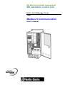
MV Electrical network management
MV substation control unit
Merlin Gerin Easergy Range
T200
Modbus II Communication
User's manual
2
MERLIN GERIN
Contents
GENERAL
4
Application ......................................................................................................... 4
Advantages ........................................................................................................ 4
Functions
4
Select before execute ........................................................................................ 4
Report by exception ........................................................................................... 4
Protocol analyser ............................................................................................... 4
Events
4
GENERAL
5
CONNECTION TO A TRANSMISSION NETWORK
6
Space available for a transmission interface
6
Connection to a transmission interface
6
COMMUNICATION MODULE
8
Communication module configuration
9
Comms parameters
10
Alarm parameters
17
MODBUS analyser
18
Equipment states
19
Front panel indications
20
Normal operation
20
Diagnosis using front panel indicators and time-stamped events
21
Replacing the Serial line module
22
MODBUS DATA ADDRESSES AND ENCODING
23
General
23
Identification / configuration zone
25
Time synchronization zone
25
Test zone
26
Event zone
26
TC / TSD / TSS zone
28
Telemetering zone
30
Diagnostic counter reading
31
Example of exchanges with MODBUS
32
Report by exception with a modem
33
Report by exception without any modem
34
Select before execute
34
APPENDIX
35
MODBUS protocol
35
Read N bits: functions n°1 and 2
37
Read N words: functions n°3 and 4
37
Write a bit: function n°5
38
Write a word: function n°6
38
Read diagnostic counters: function n°8
39
Write N consecutive words: function n°16
40
CRC 16 calculation algorithm
41
Write CRC 16 calculation in C language
41
Communication exchange table T200 - 16 ways
42
Communication exchange table T200 - 4 ways
43
Communication exchange table T200 P
44
RS 485 network
45
MERLIN GERIN
3
General
The T200-MOD2 communication board allows the connection of T200 to a
telecontrol system by using a MODBUS protocol . It includes advanced
telecommunication function and manages PSTN type of transmission
modems.
Application
Permanent and non permanent serial link with a telecontrol center by using
MODBUS protocol.
Advantages
type of transmission modem : PSTN, Radio, GSM, etc .
Advanced telecommunication functions
Configuration by PC computer
Built-in protocol analyser
Functions
Select before execute
All control order needs a double transmission:
A Select then an Execute order
A control order is executed after reception of a healthy double
transmission
Delay between select and execute is limited to 20s
Report by exception
Each alarm may be configured to be sent spontaneously to the telecontrol
centre when it changes of state.
The modem is activated through HAYES frames and after PSTN link is
established with the telecontrol centre, a MODBUS protocol is initiated.
In case of use with a permanent link transmission( private line, optical fibre)
or radio, a special MODBUS message is sent to the telecontrol centre which
then initiates a Master/Slave MODBUS protocol exchange. The T200-MOD2
board manages the collision detection.
Protocol analyser
The communication board includes a protocol analyser functionality (including
a MODBUS frame translation) available from the PC computer connected to
the communication board
This analyser allows the display of the frames which are exchanged with the
telecontrol system.
Events
The communication board memorises up to the last 200 events. Each change
of states is time tagged with an accuracy of 20ms.
4
MERLIN GERIN
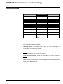
General
Accessible data
Writing of digital data
Transmission of remote control
commands to MV switches.
Transmission of the remote
control command to reset fault
currents stored.
Immediate AC supply OFF
Delayed AC supply OFF
Equipment fault,
Charger fault
Battery fault
Reading of digital data
Position of switches (SW1 to
SW16),
Switchgear supply OFF.
Reading of measurements
Remote indications:
16 phase currents (1 per way).
Status of SW1 to 16,
Diagnosis
reading of MODBUS diagnostic
Phase and earth fault currents of
counters.
ways 1 to 16,
Digital inputs 1 to 24,
Local / Remote control operating
mode,
Other functions
time synchronization function,
identification / configuration
function.
managment of up to 16 ways (4
ways by CPU)
possibility to add an other
MODBUS equipment (SEPAM,
PM300/600)
Characteristics
type of transmission
protocol
speed
data format
electrical interface
type of connector
T200 amount on a line
MERLIN GERIN
asynchronous serial
MODBUS slave
300, 600, 1200, 2400, 4800,
9600, 19200 bauds
1 start bit, 8 data bits with no parity,
1 stop bit
RS232
9 pin SUB-D, female
4080
5
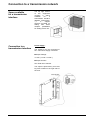
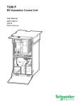
Connection to a transmission network
Space available
for a transmission
interface
The top right section
of
the
equipment
contains
a
space
available
for
a
transmission interface
(Modem, optical fibre,
...).
A
support
structure mounted on
sliding rails offers
multiple
possibilities
for adding such a unit.
Connection to a
transmission interface
Power supply :
The interface may be connected to
the ‘’Telecomms supply’’ terminals.
Output Voltage :
12 Vdc ( 10.8 to 14.8 Vdc )
Output Current :
See T200 user’s manual.
The output is protected by a 4A time
lag fuse located on the right side of
the rack.
6
MERLIN GERIN
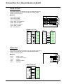
Connection to a transmission network
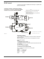
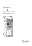
Serial I\O Port
The RS232 serial line is available on a 9 pins SUB-D female plug,
located on the right side of the rack. (only with using a RS232
modem on card "Comms").
Signals :
T200 RS232
CD : Carrier Detect
RD : Receive Data.
TD : Transmit Data.
DTR : Data Terminal Ready
DSR : Data Set Ready
RTS : Request To Send.
CTS : Clear To Send
RI : Ring Indicator
CD
DSR
RD
RTS
TD
CTS
DTR
RI
1
6
2
7
3
8
4
9
5
0V
MODEM connection
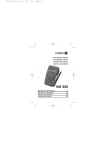
Radio Port
The RADIO connection is available on a 9 pins SUB-D female plug,
located on the right side of the rack. (only with using a Radio
modem on card "Comms") :
T200 Radio
Signals :
PTT
TX
SQ
RX
N.U.
N.U.
PTT
TX
SQ
GND
GND
GND
GND
RX
: Press To Talk.
: Transmission signal.
: Squelch.
: Reception signal.
: Not used.
1
6
2
7
3
8
4
9
5
RADIO connection
$
"
"
"
"
#
#
!
MERLIN GERIN
!
7
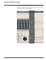
Communication module
Communication using MODBUS protocol takes place via a "COMMS" module.
The module is installed in the rack (position 3) of a "standard" T200 enclosure
( on the left side of the Power supply module).
8
MERLIN GERIN
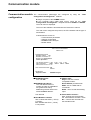
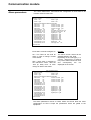
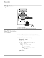
Communication module
Communication module
configuration
The communication parameters are configured by using the ‘’T200
Configuration and diagnostic’’ software.
Plug a computer to the COMMS module.
The computer being under DOS control, insert the the ‘’T200
Configuration and diagnostic’’ disquette and enter A:MG then ENTER.
The main menu is displayed.
The use of the software is described into the T200 user’s manual.
The main menu configures the protocol, the RTU address and the type of
transmission.
It allows also the access to:
- Communication parameters
- Alarmes configuration
- MODBUS frame analyser
- Modem status
T200 Comms Card MODBUS
PROM v4.05
PARAMETERS SETUP
MODBUS address : 100
MODBUS sub-address : 0
Modem type : Direct RS 232
Comms parameters
CPU Modules installed 1: yes 2: yes 3: no 4: yes
Alarm parameters
CPU 1 CPU 2 CPU 3 CPU 4
Select before execute TC : no
SAVE CONFIGURATION : OK
Cancel
DIAGNOSTIC
Equipment states
MODBUS analyser
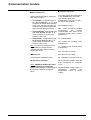
MODBUS address :
from 1 to 255
MODBUS sub-address :
This sub address allows a
number of T200 on a MODBUS
line greater than 255 by
addressing several T200 on the
same MODBUS address.
from 0 to 15
CPU Modules installed:
Yes : indicate that CPU1 (..CPU4)
is present
No : indicate that CPU1 (..CPU4)
is not present
MERLIN GERIN
Modem type :
Hayes : use of a HAYES
compatible modem.
Direct RS 232: permanent link
GSM : use of a GSM with AT
commands.
Radio : use of a radio with analog
input.
Select before execute :
Yes : Controls are received with
the ‘’Select Before excetute’’ mode
No : Controls are received with
the standard mode.
9
Communication module
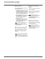
Comms parameters
1- Modem : Hayes
Comms parameters
Modem : Hayes
Host baud rate
: 9600 baud
Dialing type : Pulse
Host telephone number ( main)
: ????????
Host telephone number ( standby)
: ????????
Dial-up delay time
(0s = random value)
- first attempt
- second attempt
- third attempt
: 1s
: 1 mn
: 2 mn
Modem init : &B1E0Q0V1&C1&D2X4S0=2S2=255
Factory modem init
ESCAPE=Exit
W : Wait a second tone before
carry on the dialling. Only for a
modem that need to to dial a
Transmission speed with the telecontrol number to get an external line.
center.
Host baud rate :
200, 300, 600, 1200, 2400, 4800, 9600
or 19200 baud.
@ : Wait a 5s silence on the line
before dialling the remaining part of
the number.
Dialing type :
Host tel number (standby) :
Dialling up system.
Tone or Pulse.
Host tel number (main) :
Telephone number of the host
computer system, used to send the
alarms to the telecontrol center.
Backup telephone number used in
case of trouble with the main
telephone number.
15 figures maximum.
The dialing option are the same as
as for the main phone number.
15 figures maximum.
The telephone number can generaly
include the following dialling options
(Depend on external modem):
, (coma) : wait 2 seconds
/ (slash) : wait 125 milliseconds
10
MERLIN GERIN
Communication module
Dial up delay time :
Factory modem init :
This option allows the configuration
of the ‘’modem init’’ frame with
U.S. Robotics type( Plant
configuration). This frame is valid
first attempt : configurable from 0
to 1 mn, by step of 1 s. A ‘’0’’ value for most of the modems.
configures a random delay between
0 and 1 mn, which is compulsory to Plant initialised frame :
avoid that all equipments call at the
&B1 : Serial port speed constant
same time the telecontrol center.
(compulsory).
The
modem
second attempt : configurable from communicates with T200 at the
0 to 5 mn, by step of 1 mn. A ‘’0’’
configured speed ( menu ‘’comms
value configures a random dely
parameter’’).
between 0 and 5 mn.
Delay to transmit an alarm configured
with "delayed" option.
third attempt : configurable from 0
to 10 mn, by step of 1 mn. A ‘’0’’
value configures a random dely
between 0 and 10 mn.
Nota : The 2nd and 3rd emission are
only used by the equipment if the
preceding emission didn’t success in
sending the frame.
Modem init :
E0 : Echo disabled
Q0 : Display the resulting codes
(Compulsory).
V1 : resulting code as word format
(Compulsory).
&C1 : Normal use of DCD
&D2: Normal use of DTR
Hayes modem initialisation frame.
X4 : Activation of resulting code X4
40 characters maximum.
S0=2 Automatic answer after two
rings (Compulsory for European
norm).
Nota : NEVER PLACE the AT frame
at the beginning of initialisation
frame. T200 will send it automatically to S2=255 Disable escape code +++
(Compulsory
because
the
the modem, before the configured
transmission
frame
is
binary
frame.
coded).
MERLIN GERIN
11
Communication module
2- Modem : GSM
Comms parameters
Modem : GSM
Host baud rate : 9600 baud
PIN code
: 0000
Modbus parameters
Alarm message enabled : no
Host telephone number ( main)
Host telephone number ( standby)
Dial-up delay time
(0s = random value)
: ????????
: ????????
- first attempt
: 1s
- second attempt : 1 mn
- third attempt
: 2 mn
Short message system : SMS
Short message system enabled : no
SMS service center phone number : +33689004000
SMS user phone number : ????????
ESCAPE=Exit
Nota : Please note that it is possible
to have either an alarm on the
Transmission speed with the telecontrol control center and with a short
message on a mobile . The short
center.
message is send at first.
Must be fixed at 9600 baud with
GSM modem.
Host tel number (main) :
PIN code :
Telephone number of the host
computer system, used to send the
Setting of the PIN code into the SIM
alarms to the telecontrol center.
card (default value is 000).
In case of wrong PIN code, "GSM SIM 15 figures maximum.
card failure" appears in the screen
"Equipment states".
Host tel number (standby) :
Be care : After 3 wrong settings of
the PIN code, the SIM cardis
Backup telephone number used in
unavaible. To return to available
case of trouble with the main
status, a mobile phone must be use telephone number.
(T200 can not do it).
15 figures maximum.
Please, consult the user guide of the
SIM Card to return to an available
status.
Host baud rate :
Alarm message enabled :
Yes : If a change of state of alarms and
switch position occurs, a special
MODBUS message is send to the
telecontrol centre which then initiates a
Master/Slave MODBUS protocol
exchange.
No : T200 do not send an alarm
message.
12
MERLIN GERIN
Communication module
Dial up delay time :
Delay to transmit an alarm configured
with "delayed" option.
SMS service center phone
number:
Setting of the phone number of the
server of the SMS.
first attempt : configurable from 0
to 1 mn, by step of 1 s. A ‘’0’’ value
Please consult the user guide of
configures a random delay between
the SIM card in which this phone
0 and 1 mn, which is compulsory to
number is given.
avoid that all equipments call at the
same time the telecontrol center.
Nota : Please note that is is
second attempt : configurable from
possible to set the phone number
0 to 5 mn, by step of 1 mn. A ‘’0’’
in internationnal format. The
value configures a random dely
following format +33 6 ….can be
between 0 and 5 mn.
used in all countries.
third attempt : configurable from 0
to 10 mn, by step of 1 mn. A ‘’0’’
SMS user phone number:
value configures a random dely
between 0 and 10 mn.
Setting the phone number of the
Nota : The 2nd and 3rd emission are
mobile in wich you wish to receive
only used by the equipment if the
the short message.
preceding emission didn’t success in
sending the frame.
Nota : Please note that is is
possible to set the phone number
in internationnal format. The
Short message system enabled :
following format +33 6 ….can be
used in all countries.
Yes : When an alarm is detected, a
short message is send to a mobile.
No : The short message system is
disabled.
Nota : Please note that it is possible to
have either an alarm on the control
center and with a short message on a
mobile . The short message is send at
first.
MERLIN GERIN
13
Communication module
3- Modem : Radio
Comms parameters
Modem : Radio 600/1200 baud
Host baud rate : 1200 baud
RTS to message delay : 10ms
Handle CTS (Squelch) : no
Alarm message enabled : no
Alarm delay time
- first attempt
: 1s
(0s = random value) - second attempt : 1 mn
- third attempt
: 2 mn
ESCAPE=Exit
Host baud rate :
Alarm message enabled :
Transmission speed with the telecontrol Yes : if a the change of state of
center.
alarms and switch position occurs,
a special MODBUS message is
600 or 1200 baud.
sent to the telecontrol centre which
then initiates a Master/Slave
RTS to message delay :
MODBUS protocol exchange
It's the delay T200 will wait after RTS
before sending the message value –
depend of the radio..
Value is from 0 to 500ms default value
is 100ms.
Handle CTS (Squelch) :
Squelch, if it exist on the radio, allows
T200 to have information about the
status of the network (busy or not
busy).
If the radio network is very noisy, it can
be better to unabled this option.
No : T200 do not send an alarm
message.
Alarm delay time :
Delay to transmit an alarm
configured with "delayed" option.
first attempt : configurable from
0 to 1 mn, by step of 1 s. A
‘’0’’ value configures a random
delay between 0 and 1 mn,
which is compulsory to avoid
that all equipments call at the
same time the telecontrol
center.
second attempt : configurable
from 0 to 5 mn, by step of 1
mn. A ‘’0’’ value configures a
random dely between 0 and 5
mn.
third attempt : configurable
from 0 to 10 mn, by step of 1
mn. A ‘’0’’ value configures a
random dely between 0 and 10
mn.
Nota : The 2nd and 3rd emission
are only used by the equipment if
the preceding emission didn’t
success in sending the frame.
14
MERLIN GERIN
Communication module
4- Modem : Phone line
Comms parameters
Identified modem : Phone line
Host baud rate
: 300 baud
Dialing type
: Tone
Host tel number (main)
: ??????????
Host tel number (standby)
: ??????????
Dial up delay time
(0s = random value)
- first attempt
- second attempt
- third attempt
: 1s
: 1mn
: 2mn
ESCAPE=Exit
Host baud rate :
Dial up delay time :
Transmission speed with the telecontrol Delay to transmit an alarm
center.
configured with "delayed" option.
Configurable with 300, 600 or 1200
baud.
Dialing type :
Type of dialing using for alarm
transmission to telecontrol center.
Configurable with Tone or Pulse
(default value : Tone).
Host tel number (main) :
A ‘’0’’ value configures a
random delay between 0 and 1
mn, which is compulsory to
avoid that all equipments call at
the same time the telecontrol
center.
second attempt : configurable
from 0 to 5 mn, by step of 1
mn. (Default value : 1mn).
Telephone number of the host
computer system, used to send the
alarms to the telecontrol center.
A ‘’0’’ value configures a
random dely between 0 and 5
mn.
15 figures maximum.
third attempt : configurable
from 0 to 10 mn, by step of 1
mn. (Default value : 2mn).
Host tel number (standby) :
Backup telephone number used in case
of trouble with the main telephone
number.
15 figures maximum.
MERLIN GERIN
first attempt : configurable from
0 to 1 mn, by step of 1 s.
(Default value : 1s).
A ‘’0’’ value configures a
random dely between 0 and 10
mn.
Nota : The 2nd and 3rd emission
are only used by the equipment if
the preceding emission didn’t
success in sending the frame.
15
Communication module
5- Modem : Direct RS 232
Comms parameters
Modem : Direct RS232
Host baud rate
RTS delay
Handle CTS
Handle DCD
Handle DSR
: 9600 baud
: 20 ms
: yes
: yes
: yes
( Only if handle CTS = no)
Alarm message enabled : no
ESCAPE=Exit
Host baud rate :
Handle DCD :
Transmission speed with the
telecontrol center.
Yes : T200 uses DCD signal.
200, 300, 600, 1200, 2400, 4800,
9600 ou 19200 bauds.
No : T200 do not use DCD signal.
Handle DSR :
RTS delay :
Yes : T200 uses DSR signal.
Waiting time between RTS
activation and frame emission.
No : T200 do not use DSR signal.
This parameter is to be used only if
Handle CTS = 0.
Alarm message enabled :
Configurable from 0 to 500ms by
Yes : if a the change of state of
step of 10 ms
alarms and switch position occurs,
a
special MODBUS message is
Handle CTS :
sent to the telecontrol centre which
then initiates a Master/Slave
Yes : T200 uses a normal
MODBUS protocol exchange
RST/CTS handshake: The RTS
delay is not taken into account.
No : T200 uses the RTS delay
16
No : T200 do not send an alarm
message.
MERLIN GERIN
Communication module
Alarm parameters
The ‘’Alarm Parameters’’ menu allows the configuration of each status to be
in alarm mode for each CPU.
SWITCH ALARM
Switch 1 : no
Switch 3 : yes
Alarm Parameters CPU1
----------------------------------Switch 2 : yes
Switch 4 : no
SINGLE STATE REMOTE INDICATION ALARM
Status SW1
: no
Presence HT SW1 : yes
Status SW2
: no
Presence HT SW2 : yes
Status SW3
: no
Presence HT SW3 : yes
Status SW4
: no
Presence HT SW4 : yes
Phase fault SW1 : no
Local
: no
Earth fault SW1 A : no
Immediate AC supply OFF : no
Earth fault SW1 B : no
Delayed AC supply OFF : no
Phase fault SW2 : no
Digital input 1 : yes
Earth fault SW2 A : no
Digital input 2 : yes
Earth fault SW2 B : no
Digital input 3 : yes
Phase fault SW3 : no
Digital input 4 : yes
Earth fault SW3 A : no
Digital input 5 : yes
Earth fault SW3 B : no
Digital input 6 : yes
Phase fault SW4 : no
Charger/FPI fault : no
Earth fault SW4 A : no
Battery fault : no
Earth fault SW4 B : no
SW supply OFF : no
ESCAPE=Exit
Each status could be configure as:
Remark :
no : The T200 do not send an
alarm in case of change of state
of this status.
The above screen shows all the
available status in the T200.
Depending on the T200 type ( 1 or
4 ways , internal FPI or external
FPI), some status should not exist
and
consequently
are
not
displayed on the screen.
Yes : T200 send a message to
the telecontrol center, after the
‘’dial up delay time’’ at each
change of state of the status.
SWITCH ALARM
Switch 5 : no
Switch 7 : yes
Alarm Parameters CPU2
-----------------------------------Switch 6 : yes
Switch 8 : no
SINGLE STATE REMOTE INDICATION ALARM
Status SW5
: no
Presence HT SW5 : yes
Status SW6
: no
Presence HT SW6 : yes
Status SW7
: no
Presence HT SW7 : yes
Status SW8
: no
Presence HT SW8 : yes
Phase fault SW5 : no
Earth fault SW5 A : no
Earth fault SW5 B : no
Phase fault SW6 : no
Digital input 7 : yes
Earth fault SW6 A : no
Digital input 8 : yes
Earth fault SW6 B : no
Digital input 9 : yes
Phase fault SW7 : no
Digital input 10 : yes
Earth fault SW7 A : no
Digital input 11 : yes
Earth fault SW7 B : no
Digital input 12 : yes
Phase fault SW8 : no
Earth fault SW8 A : no
Earth fault SW8 B : no
ESCAPE=Exit
The alarm parameters menus of CPU2, CPU3 and CPU4 allow the same
configuration as CPU1 except the parameters which are global to the
equipment.
MERLIN GERIN
17
Communication module
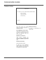
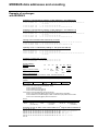
MODBUS analyser
The equipment includes a protocol
analyser function( with a modbus
frame specific decoding) . This
function is accessible from the
MODBUS analyser’’ menu on the
PC connected to the COMMS card
configuration plug.
Warning : The CPU includes also a
MODBUS analyser allowing the
display
of
MODBUS
internal
exchange between CPU
and
COMMS modules.
MODBUS analyser
ESCAPE=Exit, SPACE=Pause, C=Clear, F=Toggle filtering
34:56.67 read ts
<
01 03 00 34 00 08 05 C2
34:56.67 READ TS
>> 01 03 10 00 08 00 00 00 04 00 00 00 00 00 80 00 00 00
00 F8 B1
34:57.05 read tm
<
01 03 00 40 00 05 84 1D
34:57.05 READ TM
>> 01 03 0A 00 00 00 00 00 00 00 00 00 00 24 B6
34:57.27 read date
<
01 03 00 02 00 04 E5 C9
34:57.27 READ DATE >> 01 03 08 00 60 0A 19 10 22 DF B6 95 F5
Pause...
Use:
Display:
The "SPACE" key is used to stop
The first column gives the time of
scrolling, thereby facilitating
the message in minutes, seconds
analysis of the frames received.
and 100ths of seconds.
The "C" key clears the screen.
The second column indicates the
type of frame. Upper case
The ‘’F’’ key changes the filtering characters are used for frames
transmitted by the T200. This is
method.
confirmed by the double chevron
Display all received frames
'>>' in column 3. On the other
Display only frames
hand, all the lower case characters
destinated to this T200.
pertain to frames received by the
remote control station (confirmed
The "ESCAPE" key is used to by a single chevron '<' in column
exit the analyser function.
3).
The last column displays the
frame in hexadecimal form. The
"+" and ' * ' signs may precede the
display of the frame:
The '+' sign indicates frames not
intended for the equipment,
The ' * ' sign indicates an
erroneous
frame
(incomplete
frame, faulty construction, ...).
18
MERLIN GERIN
Communication module
Equipment states
Equipment states
---------------------
CPU - MODBUS comms failure : Module1 Module2 Module3 Module4
Modem not identified
Calling mode inhibited
Alarm processing...
ESCAPE=Exit
This menu shows the modem
Alarm processing ...
status (A selected information is
displayed as bold)
An alarm is in processing or in
repeat mode.
CPU-MODBUS comms failure:
T200 doesn’t recognise the CPU1
or CPU2 or CPU3 or CPU4; It is
either not connected either the
CPU is not valid.
Modem not identified :
T200 doesn’t recognise the
modem; It is either not connected
either the initialisation frame is not
valid.
Number blacklisted :
(Only with Hayes modem).
At least one of the telephone
number doesn’t work after some
trials. (Generaly 6; this function is
managed by the modem itself).
MERLIN GERIN
19
Communication module
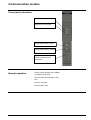
Front panel indications
Equipment is sending data
Equipment is receiving data
Communication module in fault
Communication module powered
plug for the connction of a PC
used for configuration and
maintenance
Normal operation
During normal operation the COMMS
card display is as follow:
TD and RD communication LEDs
OFF
ON is energized
Fault LED is OFF
20
MERLIN GERIN
Communication module
Diagnosis using front
panel indicators and
time-stamped events
T200 includes time stamped facilities in order to help in the diagnostic. The events are memorized into the
CPU module.
The Time stamped events can be read locally from a lap top PC computer connected to the CPU configuration
plug and equiped with the software : ‘’T200 Configuration and Diagnostic’’.
Connect the Lap top to the CPU card.
The PC being powered, and under Dos control, insert the disquette ‘’T200 Configuration and
Diagnostic’’ into the driver and press A:MG then ENTER (Capital letter either not). The main menu is
displayed.
For information on the use of the configuration software package, refer to the chapter entitled "Commissioning"
in the T200 user's manual.
Event
Possible cause
The "ON" LED on the Equipment is not powered
COMMS card is OFF.
Control unit supply fuse is burnt
Solution
Power the equipment
Change the fuse on the Power supply
unit.
Fuse : 5x20mm, 0.8A semi time lag.
Comms card failure.
Change the Comms card.
The "FAULT" LED on the The modem connected to the T200 Connect a correct modem
COMMS card is steady is not recognised or doesn’t work
properly
ON.
At least one of the
number doesn’t answer.
telephone Check:
- The phone numbers
- The complete chain of use
- The modem standard options (
generaly setup by switches on the
modem).
Reset the Hayes modem and the T200.
The "FAULT" LED on the The comms card software is in fault Press ‘’General RESET’’ button on the
Power supply unit. If the led doesn’t turn
COMMS card is flashing
OFF some seconds later, change the
ON.
comms card.
Change the Comms card.
The "Equipment fault" Comms card failure.
LED on the "Control
panel" module is ON.
and
presence of MODBUS
comms failure event
MERLIN GERIN
21
Communication module
Replacing the
Serial line module
Removing the module
a) switch off the control unit,
Switch Off the AC supply
Disconnect the batteries
b) unscrew the two module locking screws and extract it from its location.
Installing the module
a) install the new board and lock it to its slot,
b) switch the control unit on again.
IMPORTANT: Do not forget to configure the module; refer to the
sections entitled "configuration of access mode" and "configuration of
communication parameters"
22
MERLIN GERIN
MODBUS data addresses and encoding
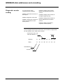
General
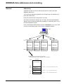
Addressing
A MODBUS master can access 255 storage spaces of 64K words (255
MODBUS addresses).
To increase the addressing capability, each storage space is divided into 16
parts (256 words each).
Each part represents the storage space of a T200.
This makes it possible to dialogue with 16 T200s, with the same MODBUS
address which increase the addressing capability to 4 080 T200 (255 x 16 ) in
the same MODBUS network.
In the documentation which follows, the term "sub-address" (0 to 15) is used
to refer to the storage position of the T200 in a MODBUS address.
master
MODBUS Address 1 MODBUS Address 2 MODBUS Address 3
FFFFh
T200 255
T200 x
T200 x
64 K words
0000h
MODBUS Address 255
T200 x
64 K words
64 K words
64 K words
T200 1
T200 x
T200 x
T200 x
T200 0
T200 x
T200 x
slave
slave
T200 x
slave
slave
MODBUS Address 1(may contain up to 256 T200)
(The T200 storage position is configured by the sub-address)
64 K words
FFFFh
Non addressable
0FFFh
0F00h
T200 15
sub-address 15 T200 255 of the address 0F00h to 0FFFh
...
0100h
0000h
MERLIN GERIN
T200 1
sub-address 1
T200 1 of the address 0100h to 01FFh
T200 0
sub-address 0
T200 0 of the address 0000h to 00FFh
23
MODBUS data addresses and encoding
Transmission
asynchronous, 300 to 19200 bauds
1 start bit, 8 data bits, 1 stop bit, no parity
maximum response time < 30ms.
Reply messages
Upon receipt of a request recognized by the equipment (read or write),
transmission of the data corresponding to the MODBUS specifications.
Upon receipt of a request not recognized by the equipment, transmission
of an exception message (type 1, 2 or 3 only).
Read zone
The number of words read may not exceed the size of the checked zone.
Some zones may only be accessed as a whole.
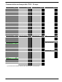
Remarks
The bit by bit write and read functions are not used in the T200
application.
Values followed by the letter "h" are in hexadecimal form (e.g. 0003h).
In the charts describing the data exchanged between the master and the
T200, the hatched strips in the "authorized function" columns indicate the
zones that are accessible as a whole.
Terminology
TCD: remote control (encoded in 2 bits)
TSD: two-state remote indication (encoded in 2 bits)
TSS: single-state remote indication (encoded in 1 bit)
TM: telemetering (encoded in 16 bits)
Control orders
The control orders could be received with the ‘’Select Before Execute’’
mode. This mode is configurable from the main configuration menu of
communication card.
24
MERLIN GERIN
MODBUS data addresses and encoding
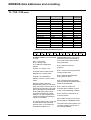
Identification /
configuration zone
word
address access mode
0000h to 0001h
0000h
read
0001h
read/write
Software version
Status
Bit 0 of status indicates:
Bit 15 of status indicates:
0 = "Scale conversion"
telemetering mode.
0 = No events loss
1 = "Raw data" telemetering mode.
The T200 preset mode is "Scale
conversion".
Time synchronization
zone
authorized
function
3,4
3,4,6
1 = Loss of events
This bit is set when the event file is
full. The event ‘’event loss’’ is then
placed in the file. As long as this
event is in the file, no other event
can be memorized. This bit is reset
when the file is empty. This chenge
of state doesn’t initiate an event.
This zone contains the internal
The zone may only be read or
date and time of the equipment for written as a whole.
time-stamping of events.
binary date
year
month+day
hours+minutes
milliseconds
word address
0002h to 0005h
0002h
0003h
0004h
0005h
access mode
read/write
read/write
read/write
read/write
0
Year (0 to 99)
b15
b8
0
b15
b7
b0
month (1 to 12)
b15
b8
0
authorized
function
3,4,16
3,4
3,4
3,4
0
b7
hour
b0
0
b8
day (1 to 31)
b7
minute (0 to 59)
b0
millisecond (0 to 59999)
b15
MERLIN GERIN
b8
b7
b0
25
MODBUS data addresses and encoding
Test zone
Event zone
The test zone contains 9 words
that can be read or written. It is
preset to zero status and is
available to users to facilitate final
adjustment tests.
The contents of the zone do not
have any effect on the T200
functions.
Test zone
word address
access mode
9 words
0006h to 000Eh read/write
authorized
function
1,2,3,4,5,6,16
This zone contains the time stamp
events.
Event zone
exchange word
event 1
event 2
event 3
event 4
word
address
000Fh
0010h
0017h
0018h
001Fh
0020h
0027h
0028h
002Fh
access mode
read/write
to read
authorized
function
3,4,6,16
3,4
to read
3,4
to read
3,4
to read
3,4
Only the exchange word may be
written.
It is possible to read the exchange
zone as a whole or the exchange
word only.
The exchange word is used to
manage a specific protocol to be
sure not to lose events as a result
of a MODBUS communication
problem; the event table is
numbered for that purpose.
The exchange word comprises 2
bytes:
Most significant byte = exchange
number which identifies each
event frame. It is preset to zero
when the T200 is switched on;
when it reaches its maximum
value (FFh), it automatically goes
back to 0. The T200 numbers the
exchanges and the master
acknowledges the numbering.
Least significant byte = number
of valid events in the event zone
(maximum 4).
26
MERLIN GERIN
MODBUS data addresses and encoding
Encoding of events
Acknowledgment of events
Each event is encoded with 4
words related to the event,
followed by 4 words containing the
event time-stamping data:
To inform the T200 that it has
correctly received the frame it has
read, the master must :
word1: 0800h /2048
word2: event bit address
writes the number of the last
exchange it has received in the
"exchange number" byte
resets the "number of events"
001Fh /31:
byte
of the exchange word to zero.
Event loss bit ( set only on
appearance)
0340h to 036Fh / 832 to 879:
TSD 1 to 24
0370h to 0375h /880 to 885 :
code CR
After acknowledgment, the T200
erases the events that have
already been transmitted and
replaces them by new ones when
applicable.
Remark: until the exchange word
written by the master becomes
"X,0" (with X = number of the
previous exchange that the master
word3: 0
wishes to acknowledge), the
word4: 0 = 0 to 1 change of state exchange word in the table
1 = 1 to 0 change of state remains at "X, number of previous
events".
words 5 to 8: time-stamping with
If the number is equal to zero, the
same format as date zone.
master is not required to
acknowledge a message with no
event.
0380h to 03BFh / 896 to 959:
TSS 1 to 64
MERLIN GERIN
27
MODBUS data addresses and encoding
TC / TSD / TSS zone
TCD / TSD / TSS
word adddress
access mode
TCD 1-8
TCD 9-16
TCD 17-24
reserved
TSD 1-8
TSD 9-16
TSD 17-24
CR
TSS 1-16
TSS 17-32
TSS 33-48
TSS 49-64
TSS 65-80
TSS 81-96
TSS 97-112
TSS 113-128
0030h
0031h
0032h
0033h
0034h
0035h
0036h
0037h
0038h
0039h
003Ah
003Bh
003Ch
003Dh
E
003 h
003Fh
write
write
write
write
read
read
read
read
read
read
read
read
read
read
read
read
function
authorized
1,2,3,4,5,6
1,2,3,4,5,6
1,2,3,4,5,6
1,2
1,2,3,4
1,2,3,4
1,2,3,4
1,2,3,4,5,6
1,2,3,4
1,2,3,4
1,2,3,4
1,2,3,4
1,2,3,4
1,2,3,4
1,2,3,4
1,2,3,4
Each TCD word is encoded as follows:
TCD8
C
b15
O
TCD7
C
O
TCD6
C
O
TCD5
C
TCD4
O
C
b8
b7
O
TCD3
C
O
TCD2
C
O
TCD1
C
O
b0
A remote control TCD is encoded The CR code (result code) gives
in 2 bits:
information on the processing of
the remote control order carried
01 = open order
out by the T200:
10 = closing order
The TCDs are assigned as
bit 0: Remote control in
follows:
progress.
TCD1..16 : Switch 1..16.
bit 1: Fault concerning the initial
TCD18: reset of fault current
remote control order
detectors by a closing order.
bit 2: Serious fault detected
TCD21..24: Automatism
during internal check.
ON/OFF of CPU1, CPU2, CPU3,
CPU4
bit 3: External fault; the switch
has not reached the desired status
Remote control orders are
within the time allotted.
performed by writing a TCD word.
Only one remote control order at a
bit 4: Remote control not
time may be requested. The order executed due to Station in Local
type is the status complementary
mode or other disabling condition.
to the TSD status (only one bit
should be included in the word
bit 5: Failure to execute for an
written). It is only accepted if the
unknown reason.
T200 is not already processing a
remote control order.
Each chane of state of one of this
bit will produce a MODBUS event.
The control order zone ( TCD) may
be read with bit and word read
The telecontrol center system may
function code. As it contains no
reset this codes by writing a 0 to
information the data is 0.
the relevant address.
28
MERLIN GERIN
MODBUS data addresses and encoding
Each TSD word is encoded as follows:
TSD8
C
O
TSD7
C
O
TSD6
C
O
TSD5
C
b15
A TSD is encoded in 2 bits, F,O
TSD4
O
C
b8
b7
TSD3
O
C
O
TSD2
C
TSD1
O
C
O
b0
The TSDs are assigned as follows:
01 = switch open.
TSD1: Switch 1.
10 = switch closed.
TSD2: Switch 2.
00 or 11 = undetermined.
TSD3: Switch 3.
For automatism only :
TSD4: Switch 4.
11 = automatism locked by
internal problem
TSD18: Corresponds to fault
current detector reset order. The
status is set to 01.
00 = automatism locked by
external TSS
Each TSS word is encoded as follows:
TSS16 TSS15 TSS14 TSS13 TSS12 TSS11 TSS10 TSS9
b15
CPU 1 (4 ways)
Single remote indications
TSS1 : Phase fault SW 1.
TSS2 : Earth fault A SW 1.
TSS3 : Phase fault SW 2.
TSS4 : Earth fault A SW 2.
TSS5 : Phase fault SW 3.
TSS6 : Earth fault A SW 3.
TSS7 : Phase fault SW 4.
TSS8 : Earth fault A SW 4.
TSS9 : Earth switch SW 1.
TSS10 :Earth switch SW 2.
TSS11 :Earth switch SW 3.
TSS12 :Earth switch SW 4.
TSS13 :Earth fault B SW 1.
TSS14 :Earth fault B SW 2.
TSS15 :Earth fault B SW 3.
TSS16 :Earth fault B SW 4.
TSS17 :Digital input 1.
TSS18 :Digital input 2.
TSS19 :Volt. presence SW1
TSS20 :Volt. presence SW2
TSS21 :Volt. presence SW3
TSS22 :Volt. presence SW4
TSS23 :Local.
TSS24 :Im. AC sup OFF.
TSS25 :Digital input 3.
TSS26 :Charger fault.
TSS27 :Battery fault.
TSS28 :SW. supply OFF.
TSS29 :Del. AC sup. OFF.
TSS30 :Digital input 4.
TSS31 :Digital input 5.
TSS32 :Digital input 6.
MERLIN GERIN
b8
optionnal CPU2 (8 ways)
Word bit
38h 0
38h 1
38h 2
38h 3
38h 4
38h 5
38h 6
38h 7
38h 8
38h 9
38h 10
38h 11
38h 12
38h 13
38h 14
38h 15
39h 0
39h 1
39h 2
39h 3
39h 4
39h 5
39h 6
39h 7
39h 8
39h 9
39h 10
39h 11
39h 12
39h 13
39h 14
39h 15
Single remote indications
TSS33 :Phase fault SW 5
TSS34 :Earth fault A SW 5
TSS35 :Phase fault SW 6
TSS36 :Earth fault A SW 6
TSS37: Phase fault SW 7
TSS38: Earth fault A SW 7
TSS39: Phase fault SW 8
TSS40: Earth fault A SW 8
TSS41: Earth switch SW 5
TSS42 :Earth switch SW 6
TSS43 :Earth switch SW 7
TSS44 :Earth switch SW 8
TSS45 :Earth fault B SW 5
TSS46 :Earth fault B SW 6
TSS47 :Earth fault B SW 7
TSS48 :Earth fault B SW 8
TSS49 :Digital input 7
TSS50 :Digital input 8
TSS51 :Volt. Presence SW5
TSS52 :Volt. Presence SW6
TSS53 :Volt. Presence SW7
TSS54 :Volt. Presence SW8
TSS55 :Reserved
TSS56 :Reserved
TSS57 :Digital input 9
TSS58 :Reserved
TSS59 :Reserved
TSS60 :Reserved
TSS61 :Reserved
TSS62 :Digital input 10
TSS63 :Digital input 11
TSS64 :Digital input 12
Word bit
3Ah 0
3Ah 1
3Ah 2
3Ah 3
3Ah 4
3Ah 5
3Ah 6
3Ah 7
3Ah 8
3Ah 9
3Ah 10
3Ah 11
3Ah 12
3Ah 13
3Ah 14
3Ah 15
3Bh 0
3Bh 1
3Bh 2
3Bh 3
3Bh 4
3Bh 5
3Bh 6
3Bh 7
3Bh 8
3Bh 9
3Bh 10
3Bh 11
3Bh 12
3Bh 13
3Bh 14
3Bh 15
TSS8
TSS7
TSS6
b7
TSS5
TSS4
TSS3
TSS2
TSS1
b0
optionnal CPU3 (12 ways) optionnal CPU4 (16 ways)
Single remote indications
Word bit
TSS65 :Phase fault SW 9
3Ch 0
TSS66 :Earth fault A SW 9 3Ch 1
TSS67 :Phase fault SW 10 3Ch 2
TSS68 :Earth fault A SW 10 3Ch 3
TSS69: Phase fault SW 11 3Ch 4
TSS70: Earth fault A SW 11 3Ch 5
TSS71: Phase fault SW 12 3Ch 6
TSS72: Earth fault A SW 12 3Ch 7
TSS73: Earth switch SW 9 3Ch 8
TSS74 :Earth switch SW 10 3Ch 9
TSS75 :Earth switch SW 11 3Ch 10
TSS76 :Earth switch SW 12 3Ch 11
TSS77 :Earth fault B SW 10 3Ch 12
TSS78 :Earth fault B SW 11 3Ch 13
TSS79 :Earth fault B SW 12 3Ch 14
TSS80 :Earth fault B SW 13 3Ch 15
TSS81 :Digital input 13
3Dh 0
TSS82 :Digital input 14
3Dh 1
TSS83 :Volt. presence SW9 3Dh 2
TSS84 :Volt. presence SW10 3Dh 3
TSS85 :Volt. presence SW11 3Dh 4
TSS86 :Volt. presence SW12 3Dh 5
TSS87 :Reserved
3Dh 6
TSS88 :Reserved
3Dh 7
TSS89 :Digital input 15
3Dh 8
TSS90 :Reserved
3Dh 9
TSS91 :Reserved
3Dh 10
TSS92 :Reserved
3Dh 11
TSS93 :Reserved
3Dh 12
TSS94 :Digital input 16
3Dh 13
TSS95 :Digital input 17
3Dh 14
TSS96 :Digital input 18
3Dh 15
Single remote indications
Word bit
TSS97 :Phase fault SW 13 3Eh 0
TSS98 :Earth fault A SW 13 3Eh 1
TSS99 :Phase fault SW 14 3Eh 2
TSS100:Earth fault A SW 14 3Eh 3
TSS101: Phase fault SW 15 3Eh 4
TSS102: Earth fault A SW 15 3Eh 5
TSS103: Phase fault SW 16 3Eh 6
TSS104: Earth fault A SW 16 3Eh 7
TSS105: Earth switch SW 13 3Eh 8
TSS106:Earth switch SW 14 3Eh 9
TSS107:Earth switch SW 15 3Eh 10
TSS108:Earth switch SW 16 3Eh 11
TSS109:Earth fault B SW 13 3Eh 12
TSS110:Earth fault B SW 14 3Eh 13
TSS111:Earth fault B SW 15 3Eh 14
TSS112:Earth fault B SW 15 3Eh 15
TSS113:Digital input 19
3Fh 0
TSS114:Digital input 20
3Fh 1
TSS115:Volt.presence SW13 3Fh 2
TSS116:Volt.presence SW14 3Fh 3
TSS117:Volt.presence SW15 3Fh 4
TSS118:Volt.presence SW16 3Fh 5
TSS119:Reserved
3Fh 6
TSS120:Reserved
3Fh 7
TSS121:Digital input 21
3Fh 8
TSS122:Reserved
3Fh 9
TSS123:Reserved
3Fh 10
TSS124:Reserved
3Fh 11
TSS125:Reserved
3Fh 12
TSS126:Digital input 22
3Fh 13
TSS127:Digital input 23
3Fh 14
TSS128:Digital input 24
3Fh 15
29
MODBUS data addresses and encoding
Telemetering zone
32 TM
Phase current way 1
Phase current way 2
Phase current way 3
Phase current way 4
Phase current way 5
Phase current way 6
Phase current way 7
Phase current way 8
Phase current way 9
Phase current way 10
Phase current way 11
Phase current way 12
Phase current way 13
Phase current way 14
Phase current way 15
Phase current way 16
TM reserved
Word address
Hexa.
decimal
0040h
64
0041h
65
0042h
66
0043h
67
0044h
68
0045h
69
0046h
70
0047h
71
0048h
72
0049h
73
004Ah
74
004Bh
75
004Ch
76
004Dh
77
004Eh
78
004Fh
79
0050h à 80 à 95
005Fh
access
mode
read
read
read
read
read
read
read
read
read
read
read
read
read
read
read
read
read
function
authorized
3,4
3,4
3,4
3,4
3,4
3,4
3,4
3,4
3,4
3,4
3,4
3,4
3,4
3,4
3,4
3,4
3,4
Each TM value is a signed value encoded in 2's complement 16-bit word.
Depending on the calibration mode configured (in the identification zone), the
value should be interpreted as follows:
"Raw data" mode: This is a value over +/-32767. For current metering, it is
always positive and reaches +32767 as the maximum value. To find out the
current value, it is necessary to convert :
I = A * val + B.
Example: for a full scale at 400 Amps, a TM value read as 8192 (2000h)
corresponds to 8192 * 400 / 32767 + 0 = 100 A.
"Scale conversion" mode: This is the direct value of what is measured.
Example: if the equipment measures 387 Amps, the value of the TM read will
be +387.
In both operating modes, invalid or non-declared measurements are encoded
with the value 8000h (-32768).
30
MERLIN GERIN
MODBUS data addresses and encoding
Diagnostic counter
reading
The sub-function codes
recognized by the T200 are:
000Ch: reading of the number
frames received with CRC errors
(CPT2).
0000h: T200 returns an echo of
the request.
000Dh: reading of the number of
exception replies (CPT3).
000Ah: diagnostic count reset.
000Bh: reading of the number of
frames received with no CRC
errors (CPT1).
000Eh: reading of the number of
frames addressed to the station
(CPT4).
000Fh: reading of broadcast
requests received (CPT5).
The most significant bit of the sub-function code should be assigned with
the sub-address of the T200 to be accessed.
sub-function code = 0B
T200 sub-address = 3
CRC16
Reading:
01
08
03
0B
00
00
91
8D
Reply:
01
08
03
0B
00
04
90
4E
T200 address = 1
Function code = 8
MERLIN GERIN
31
MODBUS data addresses and encoding
Example of exchanges
with MODBUS
Reading of TSs followed by reading of TMs (Address=1, sub-address=0)
07:56.29 read
07:56.30 READ
ts
TS
07:56.52 read
07:56.52 READ
tm
TM
< 01 03
>> 01 03
00 1B
< 01 03
>> 01 03
00
10
46
00
08
34 00 08 05 C2
00 6A 00 00 00 04 00 00 00 00 00 00 00 00 00
40 00 04 45 DD
00 00 80 00 80 00 80 00 C2 17
Reading of TSs followed by reading of TMs (Address=1, sub-address =4)
07:56.29 read
07:56.30 READ
ts
TS
07:56.52 read
07:56.52 READ
tm
TM
< 01 03
>> 01 03
00 1B
< 01 03
>> 01 03
04
10
46
04
08
34 00 08 04 F2
00 6A 00 00 00 04 00 00 00 00 00 00 00 00 00
40 00 04 44 ED
00 00 80 00 80 00 80 00 C2 17
Writing of the broadcast date followed by a reread
08:25.48 write date
07:56.74 read date
07:56.74 READ DATE
< 00 10 00 02 00 04 08 00 60 09 1E 0A 05 A0 32 AC 2C
< 01 03 00 02 00 04 E5 C9
>> 01 03 08 00 60 09 1E 0A 07 DD A4 B7 B8
Opening of TC n°1 followed by reading of TSs (and code CR=01)
08:12.21
08:12.21
08:14.69
08:14.69
write
WRITE
read
READ
tc
TC
ts
TS
<
>>
<
>>
01
01
01
01
00
06
06
03
03
55
00
00
00
10
D7
30
30
34
00
00
00
00
69
01
01
08
00
48
48
05
00
05
05
C2
00 04 00 01 00 00 00 00 00 00 00
Resetting of diagnostic counters
29:04.89 diag.cpt
29:04.90 DIAG.CPT
< 01 08 FA 0A 00 00 F0 D1
>> 01 08 FA 0A 00 00 F0 D1
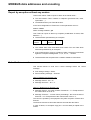
Event reading :
Request :
01
03
00
0F
00
Event
addres
Reply in case of no event :
01
03
02
2 bytes
01
B4 C9
1 word
CRC16
XX
00
event
tag
no
event
XX XX
CRC16
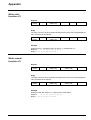
Reply in case of events:
In case of events, the frame contains 4 events. The frame structure is:
Header
Event 1
Event 2
Event 3
Event 4
CRC16
5 bytes
16 bytes
Header :
01
03
16 bytes
Slave address
16 bytes
16 bytes
2 bytes
42
XX
04
Bytes nb
(66 bytes)
Event tag
Event number
In the frame
If the event is an internal event (local/remote, fault):
Event 1 is the event itself
Event 2 and Event 3 are only 00
Event 4 is a result code (@ 37h)
If the event is a control order from the control centre :
Event 1 is a result code (@37h) with bit 0 set to 1 (telecontrol in progress)
Event 2 and Event 3 are the change of state of close and open position of the switch.
Event 4 is a result code (@37h) with bit 0 reset to 0
Event :
08 00
Always
08 00
XX XX
00 00
00 0X
Bit address
03 97
(word 39h bit 7)
Always
00 00
X=new value
0 : bit is reset
1 : bit is set
00 63 08 0C OE 12 91 DC
YY MM DD HH MM millisec
99 / 08 / 12
14:18 44252 ms
(44s 252ms)
th
Example of reply on SW1 close control order at 12 August 1999 10:39:09 510
01
08
08
08
08
C2
32
03
00
00
00
00
78
42
03
03
03
03
13
70
41
40
70
04
00
00
00
00
00
00
00
00
00
00
00
00
01
01
00
00
00
00
00
00
63
63
63
63
08
08
08
08
0C
0C
0C
0C
OE
OE
OE
OE
27
27
27
27
0C
0C
0C
18
58
B2
B2
74
Control in progress
SW1 close = 1
SW1 open = 0
End of control
MERLIN GERIN
MODBUS data addresses and encoding
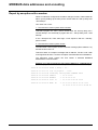
Report by exception with a modem
When an indication configured as an alarm changes of state, T200 initiates an
alarm cycle by dialling-up the main phone number after the ‘’dial-up delay time
/ first attempt’’.
Two cases can occure:
1 - The telecontrol center system doesn’t answer:
T200 dial-up again the ‘’main’’ phone number after the ‘’dial-up delay time /
second attempt’’ and eventually try again after the ‘’dial-up delay time / third
attempt’’.
If the 3 attempts fail, T200 starts agin a new sequence with the ‘’standby’’
phone number.
2 - The telecontrol center system answer :
The telecontrol center system send a broadcast message (Slave address = 0)
and the function code = 0.
T200 send back an exception message with its address, function code 0 with
most significant bit set to 1 and the exception code filled with the sub-address.
The telecontrol center system can then initiate a standard MODBUS
Master/Slave communuication.
Example of an alarm followed by TS reading (Address=1, sub-address=4)
(Frame displayed with the MODBUS analyser function of the COMMS card)
98/06/12 11:17:06.20 Alarm 1, delay = 1s...
98/06/12 11:17:07.22 Call in progress... "122"
98/06/12 11:17:30.48 Connected, calling mode "CONNECT 9600"
98/06/12 11:17:33.80 address
<
00 00 01 B0
98/06/12 11:17:33.80 ADDRESS
>> 01 80 04 40 03
98/06/12 11:17:44.74 read
ts
<
98/06/12 11:17:44.74 READ
TS
>> 01 03 10 00 9A 00 00 00 04 00
01 03 04 34 00 08 04 F2
00 00 00 00 40 00 00 00 00 EA CD
MERLIN GERIN
33
MODBUS data addresses and encoding
Report by exception without any modem
This function allows T200 to report an alarm to the master when :
The link between T200 / Master is multipoint (permanent link, radio,
optical fiber ...).
The Master doesn’t pool T200 all the time.
In this case configuration of T200 in the comms parameter menu is :
Modem : Direct
Alarm message enabled : yes
Then T200 can report an alarm by exception (modification of status, fault
detection …)
T200 transmits spontaneously an exception.
Slave
number
1 byte
00h
1 byte
Subaddress
1 byte
CRC16
2 byte
The master then must read tables and events from the T200 which
transmits spontaneously an exception.
If the master doesn’t reply by a reading of table, T200 has no transmits
again the exception message after 1, 2, 5, 10, 10, ... minutes.
T200 transmits this exception with a collision avoidance mechanism .
Select before execute
This function allows to send first a select message before the control
message.
First writing message : Select.
Second writting message :' "Execute.
Case of "Writting bit" (function n°5) :
Message "Select" : bit = "0".
Message "Execute " : bit = "1".
Case of "Writting word" (function n°6) :
Message "Select" : the word consists of all the bit = "1". Except the bit of
the control which is set to "0".
Message "Execute " : normal control proceedings : the word consists of
all the bit = "0". Except the bit of the control which is set to "1".
The control is operate by the equipment only after reception of Select and
Execute.
The Execute must be received less than 20 seconds after the Select.
In case of failure, an exception reply (03 = incorrect data) is replied to the
master.
34
MERLIN GERIN
Appendix
MODBUS protocol
MODBUS is a master - slave protocol.
It is used to read or write one or more words (16 bits), as well as diagnostic
counters.
Functions available:
1: read n output bits.
2: read n input bits.
3: read n output words.
4: read n input words.
5: write a bit.
6: write a word.
8: read diagnostic counters.
16: write several words.
Exchanges are carried out at the master's initiative and comprise a request
from the master followed by the reply from the slave. The master's requests
are addressed to a slave identified by its number in the first byte of the
frame or else addressed to all the slaves (broadcast).
Broadcast commands are necessarily write commands. No reply is
transmitted by the slaves.
Structure of frames exchanged
All the frames exchanged (request and reply) have the same structure:
Slave
number
function
code
data zone
check zone
CRC16
Each message or frame contains 4 types of information:
slave number (1 byte): it specifies the receiving equipment
(0 to FFh). If it is equal to zero, the request concerns all the slaves
(broadcast) and there is no reply message.
function code (1 byte): it is used to select a command (read, write...) and
check that the reply is correct.
data zone (n bytes): it contains the parameters linked to the function.
check zone (2 bytes): it is used to detect transmission errors.
Please note that words (2 bytes = 16 bits) are always written as high-order
bits to low-order bits, with the exception of the CRC16 which is written as
least significant bit, most significant bit.
MERLIN GERIN
35
Appendix
Synchronization of exchanges
Any character that is received after a silence of more than 3 characters is
considered as the beginning of a frame. A silence in the line equal to at
least 3 characters should be respected between two frames.
Example: at 9600 bauds, the time is equal to approximately
3 milliseconds.
Checking of messages received by the slave
When the slave receives a frame, it checks the following, in order:
CRC16, slave number, function code and function parameters.
If the CRC16 or the slave number are incorrect, the slave does not reply.
If the CRC16 and the slave number are correct, but the function code or
parameters are not valid, the slave transmits an exception reply.
If the CRC16, slave number, function code and parameters are correct,
the slave replies to the master's request.
Exception reply transmitted by the slave
Slave
number
1 byte
36
function
code
received
with MSB
set to 1
1 byte
Exception code
01 unknown function code
02 incorrect address
03 incorrect data
CRC16
1 byte
2 bytes
MERLIN GERIN
Appendix
Read N bits:
functions n°1 and 2
Function 1: read output bits.
Function 2: read input bits.
Request
Slave
number
1 byte
1 or 2
1 byte
address of 1st bit
(MSB+LSB)
2 bytes
number of bits
CRC16
2 bytes
2 bytes
Reply
Slave
number
1 byte
1 or 2
1 byte
number of
bytes read
1 byte
1st byte read
2 bytes
N bytes
last byte
read
2 bytes
CRC16
2 bytes
Example
Reading of 16 bits, bit address 300h of slave n°1, sub-address 2
Request:
01 01 23 00 00 10 36 42
Reply:01 01 02 00 00 B9 FC
Read N words:
functions n°3 and 4
The number of words to be read should be less than or equal to 125.
Function 3: read output words.
Function 4: read input words.
Request
Slave
number
1 byte
3 or 4
1 byte
address of 1st word
(MSB+LSB)
2 bytes
number of words
(MSB+LSB)
2 bytes
CRC16
2 bytes
Reply
Slave
number
3 or 4
number of
bytes read
1st word read
(MSB+LSB)
1 byte
1 byte
2 bytes
2 bytes
last word
read
(MSB+LSB)
2 bytes
CRC16
2 bytes
Example
Reading of words 40h to 43h of slave n°1, offset 0
Request:
01 03 00 40 00 04 45 DD
Reply:01 03 08 00 00 80 00 80 00 80 00 C2 17
MERLIN GERIN
37
Appendix
Write a bit:
function n°5
Request
Slave
number
1 byte
5
1 byte
address of bit
(MSB+LSB)
2 bytes
bit value
0
CRC16
1 byte
1 byte
2 bytes
Reply
The reply is an echo of the request indicating that the slave has acknowledged the
value contained in the request.
Slave
number
1 byte
5
1 byte
address of bit
(MSB+LSB)
2 bytes
bit value
0
CRC16
1 byte
1 byte
2 bytes
Example
Writing of bit to 1, bit address 301h of slave n°1, sub-addresst n°2
Request:
01 05 23 01 FF 00 D6 7E
Reply:01 05 23 01 FF 00 D6 7E
Write a word:
function n°6
Request
Slave
number
1 byte
6
1 byte
address of word
(MSB+LSB)
2 bytes
value of word
(MSB+LSB)
2 bytes
CRC16
2 bytes
Reply
The reply is an echo of the request indicating that the slave has acknowledged the
value contained in the request.
Slave
number
1 byte
6
1 byte
address of word
(MSB+LSB)
2 bytes
value of word
(MSB+LSB)
2 bytes
CRC16
2 bytes
Example
Writing of word 30h of slave n°1, offset 0 at the value 0001h
Request:
01 06 00 30 00 01 48 05
Reply:01 06 00 30 00 01 48 05
38
MERLIN GERIN
Appendix
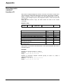
Read diagnostic
counters:
function n°8
Each slave is assigned diagnostic counters. There are 5 counters in all per slave.
The counters are 16-bit words. When they reach FFFFh, they go back to 0000h.
When a request is sent by the master, the most significant byte in the subfunction code is assigned by the T200 equipment offset to access and the data
are at 0000h.
When the slave sends a reply, the data contain the value of the counter
concerned.
Request / reply
Slave
number
1 byte
8
1 byte
sub-function code
(MSB+LSB)
2 bytes
data (MSB+LSB)
CRC16
2 bytes
2 bytes
the slave should send the echo of the request
resetting of diagnostic counters
reading of total number:
of frames received with no CRC errors (CPT1)
of frames received with CRC errors (CPT2)
of the number of exception replies (CPT3)
of frames addressed to the station (CPT4)
(excluding broadcast)
of broadcast requests received and correctly
executed (CPT5)
sub-function
code
xx00
xx0A
data
XXXX
0000
xx0B
xx0C
xx0D
xx0E
XXXX
XXXX
XXXX
XXXX
xx0F
XXXX
Sub-function n°0 is used to test transmission. The slave sends back the echo of
the data received.
Examples
Resetting of counters for slave n°1, offset 0
Request:
01 08 00 0A 00 00 C0 09
Reply:01 08 00 0A 00 00 C0 09
Reading of broadcast requests received (CPT5) for slave n°1, offset 3
(300h in storage space)
Request:
01 08 03 0F 00 00 D0 4C
Reply:01 08 03 0F 00 05 10 4F
MERLIN GERIN
39
Appendix
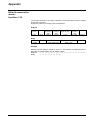
Write N consecutive
words:
function n°16
The number of words to be written is between 1 and 123 and the number of bytes
is between 2 and 246.
Words are written in increasing order of addresses.
Request
Slave
number
10h
1 byte
1 byte
address of
1st word to
write
2 bytes
number of
words to
write
2 bytes
number of
bytes to write
1 byte
values of
words to
write
N bytes
CRC16
2 bytes
Reply
Slave
number
1 byte
10h
1 byte
address of 1st word
written (MSB+LSB)
2 bytes
number of words written
(MSB+LSB)
2 bytes
CRC16
2 bytes
Example
Writing of words 0302h to 0305h of slave n°1, sub-address 3 (addresses 02h to
05h) with the values 0060h, 0A10h, 0B33h, 1662h
Request:
01 10 03 02 00 04 08 00 60 0A 10 0B 33 16 62 96 B3
Reply:
01 10 03 02 00 04 60 4E
40
MERLIN GERIN
Appendix
CRC 16 calculation
algorithm
Hex FFFF
CRC 16
CRC 16
byte
CRC 16
n=0
Shift to right CRC 16
no
carry
yes
CRC 16
poly
CRC 16
n=n+1
no
n>7
yes
Next byte
no
Messsage completed
yes
End
n = number of bits of data
poly= CRC16=1010 0000 0000 0001 calculation polynomial
Write CRC 16 calculation
in C language
Calculates and gives the CRC16 in the "buf" zone with length "len".
*buf: pointer of buffer on which the calculations are performed.
len: length of buffer.
unsigned crc16(char *buf, int len)
{
#define POLY 0xA001
char i;
unsigned crc;
for (crc =
{
crc ^=
for (i
{
if
0xFFFF; len != 0; len --)
*buf ++;
= 0; i < 8; i ++)
(crc & 0x0001)
crc = (crc >> 1) ^ POLY;
else
crc >>= 1;
}
}
return (crc);
}
MERLIN GERIN
41
Communication exchange table T200 - 16 ways
Single remote indications
TSS1 : Phase fault SW 1.
TSS2 : Earth fault A SW 1.
TSS3 : Phase fault SW 2.
TSS4 : Earth fault A SW 2.
TSS5 : Phase fault SW 3.
TSS6 : Earth fault A SW 3.
TSS7 : Phase fault SW 4.
TSS8 : Earth fault A SW 4.
TSS9 : Earth switch SW 1.
TSS10 :Earth switch SW 2.
TSS11 :Earth switch SW 3.
TSS12 :Earth switch SW 4.
TSS13 :Earth fault B SW 1.
TSS14 :Earth fault B SW 2.
TSS15 :Earth fault B SW 3.
TSS16 :Earth fault B SW 4.
TSS17 :Digital input 1.
TSS18 :Digital input 2.
TSS19 :Volt. presence SW1
TSS20 :Volt. presence SW2
TSS21 :Volt. presence SW3
TSS22 :Volt. presence SW4
TSS23 :Local.
TSS24 :Im. AC sup OFF.
TSS25 :Digital input 3.
TSS26 :Charger fault.
TSS27 :Battery fault.
TSS28 :SW. supply OFF.
TSS29 :Del. AC sup. OFF.
TSS30 :Digital input 4.
TSS31 :Digital input 5.
TSS32 :Digital input 6.
Word bit
38h 0
38h 1
38h 2
38h 3
38h 4
38h 5
38h 6
38h 7
38h 8
38h 9
38h 10
38h 11
38h 12
38h 13
38h 14
38h 15
39h 0
39h 1
39h 2
39h 3
39h 4
39h 5
39h 6
39h 7
39h 8
39h 9
39h 10
39h 11
39h 12
39h 13
39h 14
39h 15
Single remote indications
TSS33 :Phase fault SW 5
TSS34 :Earth fault A SW 5
TSS35 :Phase fault SW 6
TSS36 :Earth fault A SW 6
TSS37: Phase fault SW 7
TSS38: Earth fault A SW 7
TSS39: Phase fault SW 8
TSS40: Earth fault A SW 8
TSS41: Earth switch SW 5
TSS42 :Earth switch SW 6
TSS43 :Earth switch SW 7
TSS44 :Earth switch SW 8
TSS45 :Earth fault B SW 5
TSS46 :Earth fault B SW 6
TSS47 :Earth fault B SW 7
TSS48 :Earth fault B SW 8
TSS49 :Digital input 7
TSS50 :Digital input 8
TSS51 :Volt. Presence SW5
TSS52 :Volt. Presence SW6
TSS53 :Volt. Presence SW7
TSS54 :Volt. Presence SW8
TSS55 :Reserved
TSS56 :Reserved
TSS57 :Digital input 9
TSS58 :Reserved
TSS59 :Reserved
TSS60 :Reserved
TSS61 :Reserved
TSS62 :Digital input 10
TSS63 :Digital input 11
TSS64 :Digital input 12
Word bit
3Ah 0
3Ah 1
3Ah 2
3Ah 3
3Ah 4
3Ah 5
3Ah 6
3Ah 7
3Ah 8
3Ah 9
3Ah 10
3Ah 11
3Ah 12
3Ah 13
3Ah 14
3Ah 15
3Bh 0
3Bh 1
3Bh 2
3Bh 3
3Bh 4
3Bh 5
3Bh 6
3Bh 7
3Bh 8
3Bh 9
3Bh 10
3Bh 11
3Bh 12
3Bh 13
3Bh 14
3Bh 15
Single remote indications
Word bit
TSS65 :Phase fault SW 9
3Ch 0
TSS66 :Earth fault A SW 9 3Ch 1
TSS67 :Phase fault SW 10 3Ch 2
TSS68 :Earth fault A SW 10 3Ch 3
TSS69: Phase fault SW 11 3Ch 4
TSS70: Earth fault A SW 11 3Ch 5
TSS71: Phase fault SW 12 3Ch 6
TSS72: Earth fault A SW 12 3Ch 7
TSS73: Earth switch SW 9 3Ch 8
TSS74 :Earth switch SW 10 3Ch 9
TSS75 :Earth switch SW 11 3Ch 10
TSS76 :Earth switch SW 12 3Ch 11
TSS77 :Earth fault B SW 10 3Ch 12
TSS78 :Earth fault B SW 11 3Ch 13
TSS79 :Earth fault B SW 12 3Ch 14
TSS80 :Earth fault B SW 13 3Ch 15
TSS81 :Digital input 13
3Dh 0
TSS82 :Digital input 14
3Dh 1
TSS83 :Volt. presence SW9 3Dh 2
TSS84 :Volt. presence SW10 3Dh 3
TSS85 :Volt. presence SW11 3Dh 4
TSS86 :Volt. presence SW12 3Dh 5
TSS87 :Reserved
3Dh 6
TSS88 :Reserved
3Dh 7
TSS89 :Digital input 15
3Dh 8
TSS90 :Reserved
3Dh 9
TSS91 :Reserved
3Dh 10
TSS92 :Reserved
3Dh 11
TSS93 :Reserved
3Dh 12
TSS94 :Digital input 16
3Dh 13
TSS95 :Digital input 17
3Dh 14
TSS96 :Digital input 18
3Dh 15
Single remote indications
Word bit
TSS97 :Phase fault SW 13 3Eh 0
TSS98 :Earth fault A SW 13 3Eh 1
TSS99 :Phase fault SW 14 3Eh 2
TSS100:Earth fault A SW 14 3Eh 3
TSS101: Phase fault SW 15 3Eh 4
TSS102: Earth fault A SW 15 3Eh 5
TSS103: Phase fault SW 16 3Eh 6
TSS104: Earth fault A SW 16 3Eh 7
TSS105: Earth switch SW 13 3Eh 8
TSS106:Earth switch SW 14 3Eh 9
TSS107:Earth switch SW 15 3Eh 10
TSS108:Earth switch SW 16 3Eh 11
TSS109:Earth fault B SW 13 3Eh 12
TSS110:Earth fault B SW 14 3Eh 13
TSS111:Earth fault B SW 15 3Eh 14
TSS112:Earth fault B SW 15 3Eh 15
TSS113:Digital input 19
3Fh 0
TSS114:Digital input 20
3Fh 1
TSS115:Volt.presence SW13 3Fh 2
TSS116:Volt.presence SW14 3Fh 3
TSS117:Volt.presence SW15 3Fh 4
TSS118:Volt.presence SW16 3Fh 5
TSS119:Reserved
3Fh 6
TSS120:Reserved
3Fh 7
TSS121:Digital input 21
3Fh 8
TSS122:Reserved
3Fh 9
TSS123:Reserved
3Fh 10
TSS124:Reserved
3Fh 11
TSS125:Reserved
3Fh 12
TSS126:Digital input 22
3Fh 13
TSS127:Digital input 23
3Fh 14
TSS128:Digital input 24
3Fh 15
Single remote indications
CR0Remote ctrl in progress
CR1Remote control fault
CR2Internal fault (serious)
CR3SW posit. not reached
CR4T200 in Local
CR5Fail for unknown reason
Word bit
37h 0
37h 1
37h 2
37h 3
37h 4
37h 5
Automatism (TSD)
TSD21 :Auto CPU1 OFF
:Auto CPU1 ON
TSD22 :Auto CPU2 OFF
:Auto CPU2 ON
TSD23 :Auto CPU3 OFF
:Auto CPU3 ON
TSD24 :Auto CPU4 OFF
:Auto CPU4 ON
Word bit
36h 8
36h 9
36h 10
36h 11
36h 12
36h 13
36h 14
36h 15
Automatism (TCD)
TCD21 :Auto CPU1 OFF
:Auto CPU1 ON
TCD22 :Auto CPU2 OFF
:Auto CPU2 ON
TCD23 :Auto CPU3 OFF
:Auto CPU3 ON
TCD24 :Auto CPU4 OFF
:Auto CPU4 ON
Word bit
32h 8
32h 9
32h 10
32h 11
32h 12
32h 13
32h 14
32h 15
Events (*)
Exchange word
Event 1
Event 2
Event 3
Event 4
Word
0Fh
10h-17h
18h-1Fh
20h-27h
28h-2Fh
Double remote control
TCD1 :Switch 1 open
Switch 1 close
TCD2 :Switch 2 open
Switch 2 close
TCD3 :Switch 3 open
Switch 3 close
TCD4 :Switch 4 open
Switch 4 close
TCD5 :Switch 5 open
Switch 5 close
TCD6 :Switch 6 open
Switch 6 close
TCD7 :Switch 7 open
Switch 7 close
TCD8 :Switch 8 open
Switch 8 close
TCD9 :Switch 9 open
Switch 9 close
TCD10:Switch 10 open
Switch 10 close
TCD11:Switch 11 open
Switch 11 close
TCD12:Switch 12open
Switch 12 close
TCD13:Switch 13 open
Switch 13 close
TCD14:Switch 14 open
Switch 14 close
TCD15:Switch 15 open
Switch 15 close
TCD16:Switch 16 open
Switch 16 close
TCD 18 : Reset FPI
Reserved
word
00h
01h
02h-05h
06h-0Eh
Word
40h
41h
42h
43h
44h
45h
46h
47h
48h
49h
4Ah
4Bh
4Ch
4Dh
4Eh
4Fh
Word bit
34h 0
34h 1
34h 2
34h 3
34h 4
34h 5
34h 6
34h 7
34h 8
34h 9
34h 10
34h 11
34h 12
34h 13
34h 14
34h 15
35h 0
35h 1
35h 2
35h 3
35h 4
35h 5
35h 6
35h 7
35h 8
35h 9
35h 10
35h 11
35h 12
35h 13
35h 14
35h 15
36h 2
36h 3
Other
Version
Status
Clock synchronisation
Test area
Measure
Phase current switch 1
Phase current switch 2
Phase current switch 3
Phase current switch 4
Phase current switch 5
Phase current switch 6
Phase current switch 7
Phase current switch 8
Phase current switch 9
Phase current switch 10
Phase current switch 11
Phase current switch 12
Phase current switch 13
Phase current switch 14
Phase current switch 15
Phase current switch 16
Double remote indications
TSD1 :Switch 1 open
Switch 1 close
TSD2 :Switch 2 open
Switch 2 close
TSD3 :Switch 3 open
Switch 3 close
TSD4 :Switch 4 open
Switch 4 close
TSD5 :Switch 5 open
Switch 5 close
TSD6 :Switch 6 open
Switch 6 close
TSD7 :Switch 7 open
Switch 7 close
TSD8 :Switch 8 open
Switch 8 close
TSD9 :Switch 9 open
Switch 9 close
TSD10:Switch 10 open
Switch 10 close
TSD11:Switch 11 open
Switch 11 close
TSD12:Switch 12open
Switch 12 close
TSD13:Switch 13 open
Switch 13 close
TSD14:Switch 14 open
Switch 14 close
TSD15:Switch 15 open
Switch 15 close
TSD16:Switch 16 open
Switch 16 close
TSD 18 : Reserved (1)
Reserved (0)
word
30h 0
30h 1
30h 2
30h 3
30h 4
30h 5
30h 6
30h 7
30h 8
30h 9
30h 10
30h 11
30h 12
30h 13
30h 14
30h 15
31h 0
31h 1
31h 2
31h 3
31h 4
31h 5
31h 6
31h 7
31h 8
31h 9
31h 10
31h 11
31h 12
31h 13
31h 14
31h 15
32h 2
32h 3
(*) The 200 events stored in memory are read through a 4 events buffer
42
MERLIN GERIN
Communication exchange table T200 - 4 ways
Double remote indications
TSD1 :
Switch 1 open
Switch 1 closed
TSD2 :
Switch 2 open
Switch 2 closed
TSD3 :
Switch 3 open
Switch 3 closed
TSD4 :
Switch 4 open
Switch 4 closed
TSD 18 : Reserved: value = 1
Reserved: value = 0
wor
34h
34h
34h
34h
34h
34h
34h
34h
36h
36h
bit
0
1
2
3
4
5
6
7
2
3
Single remote indications
CR0 :
Remote control in progress
CR1 :
Remote control fault
CR2 :
Internal fault (serious)
CR3 :
Switch position not reached
CR4 :
Failure due to T200 in local
CR5 :
Failure due to unknown reason
TSS1 :
Phase fault SW 1.
TSS2 :
Earth fault A SW 1.
TSS3 :
Phase fault SW 2.
TSS4 :
Earth fault A SW 2.
TSS5 :
Phase fault SW 3.
TSS6 :
Earth fault A SW 3.
TSS7 :
Phase fault SW 4.
TSS8 :
Earth fault A SW 4.
TSS9 :
Earth switch SW 1.
TSS10 : Earth switch SW 2.
TSS11 : Earth switch SW 3.
TSS12 : Earth switch SW 4.
TSS13 : Earth fault B SW 1.
TSS14 : Earth fault B SW 2.
TSS15 : Earth fault B SW 3.
TSS16 : Earth fault B SW 4.
TSS17 : Digital input 1.
TSS18 : Digital input 2.
TSS19 : Volt. Presence SW1
TSS20 : Volt. Presence SW2
TSS21 : Volt. Presence SW3
TSS22 : Volt. Presence SW4
TSS23 : Local.
TSS24 : Immediate AC supply OFF.
TSS25 : Digital input 3.
TSS26 : Charger fault.
TSS27 : Battery fault.
TSS28 : Switchgear supply OFF.
TSS29 : Delayed AC supply OFF.
TSS30 : Digital input 4.
TSS31 : Digital input 5.
TSS32 : Digital input 6.
37h
37h
37h
37h
37h
37h
38h
38h
38h
38h
38h
38h
38h
38h
38h
38h
38h
38h
38h
38h
38h
38h
39h
39h
39h
39h
39h
39h
39h
39h
39h
39h
39h
39h
39h
39h
39h
39h
0
1
2
3
4
5
0
1
2
3
4
5
6
7
8
9
10
11
12
13
14
15
0
1
2
3
4
5
6
7
8
9
10
11
12
13
14
15
MERLIN GERIN
Double remote control
TCD1 :
opening Switch 1
closing Switch 1
TCD2 :
opening Switch 2
closing Switch 2
TCD3 :
opening Switch 3
closing Switch 3
TCD4 :
opening Switch 4
closing Switch 4
TCD18 : Fault detector reset (value = 0)
Fault detector reset (value = 1)
word
30h
30h
30h
30h
30h
30h
30h
30h
32h
32h
Remote measurements
Phase current channel 1
Phase current channel 2
Phase current channel 3
Phase current channel 4
40h
41h
42h
43h
Events
Exchange word
Event 1
Event 2
Event 3
Event 4
Miscellaneous
Version
Status
Clock synchronisation
Test zone
bit
0
1
2
3
4
5
6
7
2
3
0Fh
10h to
17h
18h to
1Fh
20h to
27h
28h to
2Fh
00h
01h
02h to
05h
06h to
0Eh
Automatism (TSD)
TSD21 :Auto CPU1 OFF
:Auto CPU1 ON
36h
36h
8
9
Automatism (TCD)
TCD21 :Auto CPU1 OFF
:Auto CPU1 ON
32h
32h
8
9
43
Communication exchange table T200 P
Double remote indications
TSD1 :
Switch open
Switch closed
TSD4 :
TSD 18 :
automatism OFF
Automatism ON
Reserved: value = 1
Reserved: value = 0
Single remote indications
CR0 :
Remote control in progress
CR1 :
Remote control fault
CR2 :
Internal fault (serious)
CR3 :
Switch position not reached
CR4 :
Failure due to T200 in local
CR5 :
Failure due to unknown reason
TSS1 :
Phase fault SW 1.
TSS2 :
Earth fault A SW 1.
TSS17 :
TSS18 :
TSS19 :
Digital input 1.
Digital input 2.
Digital input 3.
TSS23 :
TSS24 :
Local.
Immediate AC supply OFF.
TSS26 :
TSS27 :
TSS28 :
TSS29 :
TSS30 :
Charger fault.
Battery fault.
Switchgear supply OFF.
Delayed AC supply OFF.
Operated
44
wor
34h
34h
34h
34h
34h
34h
34h
34h
36h
36h
bit
0
1
2
3
4
5
6
7
2
3
37h
37h
37h
37h
37h
37h
38h
38h
38h
38h
38h
38h
38h
38h
38h
38h
38h
38h
38h
38h
38h
38h
39h
39h
39h
39h
39h
39h
39h
39h
39h
39h
39h
39h
39h
39h
39h
39h
0
1
2
3
4
5
0
1
2
3
4
5
6
7
8
9
10
11
12
13
14
15
0
1
2
3
4
5
6
7
8
9
10
11
12
13
14
15
Double remote control
TCD1 :
opening Switch 1
closing Switch 1
TCD4 :
TCD18 :
automatism OFF
Automatism ON
Fault detector reset (value = 0)
Fault detector reset (value = 1)
Remote measurements
Phase current
Measurement of voltage
Events
Exchange word
Event 1
Event 2
Event 3
Event 4
Miscellaneous
Version
Status
Clock synchronisation
Test zone
word
30h
30h
30h
30h
30h
30h
30h
30h
32h
32h
bit
0
1
2
3
4
5
6
7
2
3
40h
41h
42h
43h
0Fh
10h to
17h
18h to
1Fh
20h to
27h
28h to
2Fh
00h
01h
02h to
05h
06h to
0Eh
MERLIN GERIN
RS 485 network
A optinal board (Réf 0600) is availaible with RS 485 type in compliabce with
the EIA RS 485 standard.
Connexion to RS485 transmission network
Connection au réseau de transmission RS485
Conexión a una red de transmisión RS485
RC : Impedance matching resistor is compulsory one at each end of the network.
Résistance de boucle à mettre en service à chaque extrémité du réseau.
Résistencia de bucle a poner en servicio a cada extremidad de la red.
RP : Polarization resistor must be set only at one point of the network,
preferabily at the supervisor level.
Résistance de polarisation à mettre en service en un seul point du réseau,
de préférence au niveau du superviseur.
Résistencia de polarizatión a poner en servicio en un solo punto de la red,
preferentemente al nivel del supervisor.
RC
+5V
GND
RC
RS485
(
RP
RP
A
B
GND
A
B
GND
RP
RP
RD
TD
0V
DCD
DTR
DSR
RTS
CTS
RC
2
3
)
5
1
4
6
7
RS232
8
9
RC
+5V
GND
RS485
(
4F
+
2F
12V
RC
+5V
GND
)
POWER SUPPLY
ALIMENTATION
ALIMENTACIÓN
A
B
GND
A
RS485 / RS232
B
GND
2F
4F
RS232
2F
4F
RC
+5V
GND
)
2F : Communication 2 wires, 2 fils, 2 hilos (standard)
2F
4F
4F : Communication 4 wires, 4 fils, 4 hilos
N-0600 Ed.1
Operating problems
In case of problems, it is advisable to connect the devices to the RS 485
network one by one.
Make sure that the master sends frames to the equipment concerned.
Points to be checked
Check:
- the distributed voltage V+ (12V),
– the polarization is in one location only,
- the impedance matching is set up at the ends and only at the ends of the
RS 485 network,
- the cable use is the one advised,
- the L+ or L- lines are not earthed,
- the earthing of all the cabled shielding.
Use an oscilloscope to check the forum of the signals:
Transmit voltage
Level 0
+1.5V to +5V
Level 1
-1.5V to –5V
reception voltage threshold
Level 0
>+0.2V
Level 1
<-0.2V
MERLIN GERIN
45
Schneider Electric SA
N0484-9GB Edition : 02/2004
Postal address
F-38050 Grenoble Cedex 9
Tel.: +33 (0)4 76 57 60 60
Telex: merge 320842 F
http:\\www.schneider-electric.com
As standards, specifications and designs change from time to time, please ask for
confirmation of the information given in this publication.
Published by: Schneider Electric SA
Design and layout by: PIPET
Printed by: Hewlett Packard
Rcs nanterre B 954 503 439
46
MERLIN GERIN