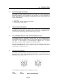
1
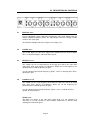
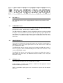
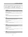
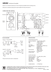
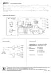
4 Channel Frequency
Conscious Noise Gate
Operation Manual
June 2005
This page has been left intentionally blank for your notes
Page 2
CONTENTS
4
1.0
OVERVIEW
2.0
2.1
2.2
2.3
2.4
2.5
2.6
2.7
2.8
2.9
2.10
2.11
DESCRIPTION OF CONTROLS
Bypass switch and led
Listen switch
Hi-Pass control
Lo-Pass control
Ext. Key led
Threshold control
Above-Below leds
Attack switch
Range switch
Release control
Link switch
5-7
3.0
3.1
3.2
3.3
3.4
3.5
3.6
EXTERNAL CONNECTIONS
Side Chain insert
Input
Output
Level switch
Power switch
Power inlet
8-9
4.0
4.1
4.2
4.3
4.4
INSTALLATION
Inspection and unpacking Phantom
Operating Environment +48V indicator
CE Standard and LVD Pad
Power Requirement Listen
5.0
WARRANTY
12
6.0
TECHNICAL SPECIFICATION
13
7.0
DIMENSIONS
14
Page 3
10-11
1.0
OVERVIEW
Main Features:
•
•
•
•
•
•
•
•
•
4 channels of Frequency Conscious Noise Gating
Variable Hi and Low Pass side chain Filters
Fully variable Threshold and Release
Fast and Slow Attack modes
Range switching between -20dB and -80dB
Side chain Listen facility
Stereo linking
Side chain inserts
Balanced Inputs-Outputs with +4dBu/10dBV switching
The G400 is a professional 4 channel noise gate that can be operated as 4 separate
processors or linked as two independant stereo pairs. In Link mode, Channel 1 and 3
provide Master control and 'rms summing' is used to ensure that signals from both the
linked channels operate the gate.
Each channel has fully variable controls for filter Frequency, Threshold and Release.
Range is switchable to provide either full muting (-80dBu) or a more subtle level of signal
attenuation (-20dBu).
Two Attack modes are available; Fast or Slow and Release is manually adjustable. Inbuilt sidechain 'auto-level-sensing' and Hold circuitry ensure that false triggering and
chatter are kept to a minimum. High and Low pass filters are included and can be used
for a wide range of frequency conscious gating applications. A LISTEN facility allows the
filters to be easily tuned by ear. Each channel also has a sidechain insert with front panel
indication when an External Key jack is plugged in.
Led indicators are provided for Above-Below Threshold, Bypass and Link.
All inputs and outputs are electronically balanced and can be switched between +4dBu
and -10dBV operating levels.
Page 4
2.0 DESCRIPTION OF CONTROLS
2.1
BYPASS switch
Pressing BYPASS cancels gating by removing the side chain voltage from the
voltage controlled amplifier (VCA). The Input-Output and level change circuitry
remain in the signal path.
The BYPASS led lights when the compressor is Bypassed.
2.2
LISTEN switch
This facility allows the side chain signal to be monitored at the channel output.
This is useful for tuning the side chain filters by ear.
2.3
HI-PASS control
This control sets the cut off frequency of the high pass filter in the side chain
signal path. Side chain signals at frequencies below the cut off frequency are
attenuated and so will not operate the gate.
Use this control to prevent low frequency signals, such as a miked up bass drum,
opening the gate.
2.4
LO-PASS control
This control sets the cut off frequency of the low pass filter in the side chain signal
path. Side chain signals at frequencies above the cut off frequency are
attenuated and so will not operate the gate.
Use this control to prevent high frequency signals, such as a miked up hi-hat
cymbal, opening the gate.
Please note:
The filters are always in the side chain signal path so if not required it is
necessary to set the controls to their extreme frequencies to prevent them
affecting the side chain signal.
Page 5
2.5
EXT. KEY led
EXT. KEY lights when a jack is plugged into the side chain insert on the rear of
the G400.
2.6
THRESHOLD control
THRESHOLD sets the reference level at which the gate will open and allow audio
through to the output. Control range is -50dBu to +20dB.
The side chain on the G400 has been designed with 'auto-level-sensing' and Hold
circuitry to ensure that both fast transient and low frequency signals operate the
gate without false triggering and/or chatter. However if the gate repeatedly opens
and closes on a particular signal, reducing the THRESHOLD level can often
correct this.
2.7
ABOVE-BELOW leds
These two leds indicate the relationship between the side chain signal (which is
normally the same as the input signal unless the side chain insert is used) and
the THRESHOLD setting.
The BELOW led indicates that the signal level is below threshold and the gate is
closed. In practise, when the BELOW led lights the audio starts to fade at a rate
set by the RELEASE control.
The ABOVE led indicates that signal levels are above threshold and the gate is
open. When the gates closes, the ABOVE led starts to fade at a rate set by the
RELEASE setting.
2.8
ATTACK switch
Two switchable ATTACK rates are available on the G400 SLOW provides an attack speed which is suitable for most program material
without introducing transient clicks.
FAST is intended for gating percussive instruments or signals with fast attacks
transients.
Page 6
2.9
RANGE switch
The RANGE switch determines the amount of signal attenuation that occurs
during gating. The G400 provides for full signal muting (-80dB) or a more subtle
attenuation (-20dB).
2.10
RELEASE control
RELEASE adjusts the speed at which the gates closes once the input signal level
has fallen below that set by the THRESHOLD control. Control range is 10mS to
4S.
Please note:
With instruments such as bass guitars, short RELEASE times can cause the gate
to chatter. If this occurs increase the release time.
2.11
LINK switch
Pressing the LINK switch couples channels 1&2 and 3&4 for stereo operation.
Channels 1 and 3 become the masters, the controls on channels 2 and 4 are
disabled.
The side chain circuitry on the G400 uses true rms summing to ensure that the
signals in both the linked channels are used to control the gate.
Page 7
3.0 EXTERNAL CONNECTIONS
3.1
SIDECHAIN
The Side chain TRS jack allows connection of an external processor such as a
parametric equaliser for more sophisticated frequency conscious gating
applications. External key signals are often used for gated-reverb, rhythmic and
bass enhancement effects.
This is an unbalanced insert with Ring wired as Send and Tip wired as Return.
Please note:
Plugging a jack into the side chain connector breaks the control signal path which
must then be completed by the externally connected equipment.
3.2
INPUT
Electronically balanced Input with pin 2 wired hot (signal +).
Unbalanced operation is possible by joining pin 3 to pin 1 (signal ground) and
using pin 2 as signal hot (+).
Please note:
To maintain correct signal levels in un-balanced applications, pin 3 must be
joined to pin 1 and not left un-connected.
3.3
OUTPUT
Electronically balanced Output with pin 2 wired hot (signal +).
For un-balanced operation pin 3 can be joined to pin 1 i.e. pin 2 = signal hot and
pins 1&3 = ground (screen).
Please note:
To maintain correct signal levels in un-balanced applications, pin 3 must be
joined to pin 1 and not left un-connected.
3.4
LEVEL
These switches select the input and output operating level for each channel
between +4dBu (switch out) and -10dBV (switch in).
Page 8
The Side Chain insert operates at -2dBu in both +4dBu and -10dBV modes.
3.5
POWER
Mains power switch for G400
3.6
POWER INLET
Standard IEC mains inlet for use with a detachable mains cable.
See Section 3.4 for details of power requirements and fusing.
Please note:
The mains protection fuse is inside the unit, accessed by removing the top cover.
Ensure that the unit is disconnected from the mains supply before attempting to
replace the fuse.
Page 9
4.0
4.1
INSTALLATION
INSPECTION AND UNPACKING
The G400 has been carefully packed at our factory in a carton designed to
withstand handling in transit. Should the unit appear to have been damaged in
transit, notify your dealer immediately and do not discard any of the packing. The
carton should contain • The G400
• Power cord - country specific, please check
• Operator Manual (this book)
4.2
OPERATING ENVIRONMENT
The G400 is designed to operate between 0°C and 40°C (32-112°F) with relative
humidity no more than 80%. Should the units be installed in an equipment rack,
ensure that the ambient temperature conforms to these levels.
4.3
CE STANDARDS AND THE LOW VOLTAGE DIRECTIVE (LVD)
The G400 has been designed to comply with the latest Electromagnetic
Compatibility (EMC) regulations. However we recommend you do not operate the
unit close to strong emitters of electromagnetic radiation such as power
transformers, motors, mobile telephones or radio transmitters.
The unit should only be connected to a power supply of the type described in 4.4
POWER REQUIREMENTS or as marked on the unit. Disconnect the mains
supply before removing any cover.
4.4
POWER REQUIREMENTS
The G400 is factory configured for either 230V 50Hz ac or 115V 60Hz ac mains
operation. Please refer to the following diagram which shows the transformer
connections for 230V and 115V –
The rating of the rear panel fuse is shown on the cover 230V
T125mA
115V
T250mA
All are slow blow type
Page 10
Please note:
If the fuse requires changing at any time please ensure the correct type is fitted.
An incorrect fuse could cause damage to the unit and may constitute a fire
hazard.
The detachable IEC mains lead connections to the appliance are coloured in
accordance with the following code:
Green-and-Yellow
Blue
Brown
Earth
Neutral
Live
WARNING: THIS APPLIANCE MUST BE EARTHED
Please note:
A protective earth connection, made by way of the earth conductor in the power
cord, is essential for safe operation.
Page 11
5.0
WARRANTY
Your LA Audio G400 has been manufactured to a high standard using quality
components. If correctly installed and operated the unit should give years of
problem free operation.
However in the event of a defect in material or workmanship causing failure of the
unit within 1 year of the date of original purchase we will agree to repair, or at our
discretion replace, any defective item without charge for labour or parts. To
receive service under this warranty it is necessary to return the unit to an LA
Audio authorised service centre or to the factory with a dated receipt as proof of
purchase. After repair the unit will be returned to you free of charge.
Limitations:
This warranty does not cover damage resulting from accident or misuse. The
warranty is void unless repairs are carried out by an authorised service centre.
The warranty is void if the unit has been modified other than at the manufacturers
instruction. The warranty does not cover components which have a limited life,
and which are expected to be periodically replaced for optimal performance. We
do not warrant that the unit shall operate in any way other than as described in
this manual.
Page 12
6.0
TECHNICAL SPECIFICATIONS
ELECTRICAL
Frequency response:
Input Impedance:
Maximum Input Level:
Input-Output Level:
20Hz to 20kHz (+0, -0.5dB)
20k balanced
+20dBu
+4dBu or -10dBV
Output Impedance:
Max. Output Level:
100R balanced
+20dBu
THD:
Signal to Noise Ratio:
< 0.05% (1kHz, +4dBu)
> 90dB, +4dBu out, 22Hz- 22kHz
Threshold:
Range:
Attack:
Release:
-50dB to +20dB
-80dB or -20dB
Fast: 50uS
Slow: 1mS
10ms to 4s - variable
High Pass Filter:
Low Pass Filter:
22Hz to 3kHz
250Hz to 30kHz
Power Requirement:
15VA, 115/230V AC, 50/60Hz
PHYSICAL
Input Connectors:
Output Connectors:
Power Connection:
XLR 3 pin (Pin 2 hot)
XLR 3 pin (Pin 2 hot)
IEC 3 pin socket, Detachable lead
Dimensions (mm):
482 (19") W
164 (6.5") D
44 (1.75") H
Weight:
Shipping Weight:
2.9 kg, 6lbs
3.6kg, 8lbs
Temperature Range:
Operating 0ºC to 50ºC
Storage -30ºC to 75ºC
Page 13
7.0
DIMENSIONS
In keeping with our policy of continuous improvement LA Audio reserves the right to alter
specifications without prior notice.
Manufactured in the UK by LA Audio
Web: www.laaudio.co.uk.
Page 14