1
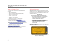
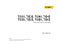
TiS10, TiS20, TiS40, TiS45 TiS50, TiS55, TiS60, TiS65 Performance Series Thermal Imagers Users Manual July 2015 © 2015 Fluke Corporation. All rights reserved. Specifications are subject to change without notice. All product names are trademarks of their respective companies. LIMITED WARRANTY AND LIMITATION OF LIABILITY Each Fluke product is warranted to be free from defects in material and workmanship under normal use and service. The warranty period is two years and begins on the date of shipment. Parts, product repairs, and services are warranted for 90 days. This warranty extends only to the original buyer or end-user customer of a Fluke authorized reseller, and does not apply to fuses, disposable batteries, or to any product which, in Fluke's opinion, has been misused, altered, neglected, contaminated, or damaged by accident or abnormal conditions of operation or handling. Fluke warrants that software will operate substantially in accordance with its functional specifications for 90 days and that it has been properly recorded on non-defective media. Fluke does not warrant that software will be error free or operate without interruption. Fluke authorized resellers shall extend this warranty on new and unused products to end-user customers only but have no authority to extend a greater or different warranty on behalf of Fluke. Warranty support is available only if product is purchased through a Fluke authorized sales outlet or Buyer has paid the applicable international price. Fluke reserves the right to invoice Buyer for importation costs of repair/replacement parts when product purchased in one country is submitted for repair in another country. Fluke's warranty obligation is limited, at Fluke's option, to refund of the purchase price, free of charge repair, or replacement of a defective product which is returned to a Fluke authorized service center within the warranty period. To obtain warranty service, contact your nearest Fluke authorized service center to obtain return authorization information, then send the product to that service center, with a description of the difficulty, postage and insurance prepaid (FOB Destination). Fluke assumes no risk for damage in transit. Following warranty repair, the product will be returned to Buyer, transportation prepaid (FOB Destination). If Fluke determines that failure was caused by neglect, misuse, contamination, alteration, accident, or abnormal condition of operation or handling, including overvoltage failures caused by use outside the product’s specified rating, or normal wear and tear of mechanical components, Fluke will provide an estimate of repair costs and obtain authorization before commencing the work. Following repair, the product will be returned to the Buyer transportation prepaid and the Buyer will be billed for the repair and return transportation charges (FOB Shipping Point). THIS WARRANTY IS BUYER'S SOLE AND EXCLUSIVE REMEDY AND IS IN LIEU OF ALL OTHER WARRANTIES, EXPRESS OR IMPLIED, INCLUDING BUT NOT LIMITED TO ANY IMPLIED WARRANTY OF MERCHANTABILITY OR FITNESS FOR A PARTICULAR PURPOSE. FLUKE SHALL NOT BE LIABLE FOR ANY SPECIAL, INDIRECT, INCIDENTAL, OR CONSEQUENTIAL DAMAGES OR LOSSES, INCLUDING LOSS OF DATA, ARISING FROM ANY CAUSE OR THEORY. Since some countries or states do not allow limitation of the term of an implied warranty, or exclusion or limitation of incidental or consequential damages, the limitations and exclusions of this warranty may not apply to every buyer. If any provision of this Warranty is held invalid or unenforceable by a court or other decision-maker of competent jurisdiction, such holding will not affect the validity or enforceability of any other provision. Fluke Corporation P.O. Box 9090 Everett, WA 98206-9090 U.S.A. 11/99 To register your product online, visit http://register.fluke.com. Fluke Europe B.V. P.O. Box 1186 5602 BD Eindhoven The Netherlands Table of Contents Title Page Introduction .................................................................................................................... How to Contact Fluke .................................................................................................... Safety Information.......................................................................................................... Operation in Extreme Conditions .............................................................................. Radio Frequency Data .............................................................................................. Accessories ................................................................................................................... SmartView Software .................................................................................................... Before You Start ............................................................................................................ Battery ...................................................................................................................... Two-Bay Battery Charger Base............................................................................ On-Imager AC Power Socket ............................................................................... Optional 12 V Vehicle Charger ............................................................................. Features and Controls .............................................................................................. Power On and Off ..................................................................................................... Controls for Image Capture ....................................................................................... Laser Pointer............................................................................................................. Control Buttons ......................................................................................................... Memory ..................................................................................................................... How to Use the Menus .............................................................................................. Image Capture ............................................................................................................... i 1 2 2 3 3 5 5 6 6 6 7 7 8 10 10 10 11 11 12 12 TiS10, TiS20, TiS40, TiS45, TiS50, TiS55, TiS60, TiS65 Users Manual IR-PhotoNotes™ ....................................................................................................... Voice Annotation (Recording) ................................................................................... Listen to a Voice Annotation (Recording) .................................................................. Edit Captured Infrared Image .................................................................................... Save Captured Infrared Image .................................................................................. Micro SD Memory Card ................................................................................................. Temperature Measurement ........................................................................................... Menus ............................................................................................................................ Measurement Menu .................................................................................................. Range ................................................................................................................... Emissivity Adjustment .......................................................................................... Background (Reflected Background Temperature Compensation) ...................... Transmission/Transmittance Adjustment ............................................................. Spot Temperatures............................................................................................... User-Definable Spot Markers ............................................................................... Center Box ........................................................................................................... Image Menu .............................................................................................................. Palettes ................................................................................................................ IR-Fusion® Technology ........................................................................................ Color Alarms ........................................................................................................ Display Graphics Presentation ............................................................................. Logo ..................................................................................................................... Camera Menu ........................................................................................................... Backlight ............................................................................................................... Video .................................................................................................................... Auto Capture ........................................................................................................ Memory Menu ........................................................................................................... Review Image Files .............................................................................................. Edit Image Files.................................................................................................... Delete Image Files ............................................................................................... Settings Menu ........................................................................................................... Units ..................................................................................................................... File Format ........................................................................................................... Auto Off ................................................................................................................ ii 12 13 14 14 14 15 15 16 16 16 18 19 19 20 20 21 22 22 23 24 26 26 27 27 27 28 29 29 29 29 30 30 30 31 Contents (continued) Localization .......................................................................................................... Language ............................................................................................................. Wireless Connectivity ........................................................................................... Image Storage...................................................................................................... Fluke Connect™ Wireless System ....................................................................... Advanced Settings .................................................................................................... Filename Prefix .................................................................................................... Reset Filename .................................................................................................... Factory Defaults ................................................................................................... Imager Information ............................................................................................... Adjust Parallax ..................................................................................................... Maintenance .................................................................................................................. How to Clean the Case ............................................................................................. Lens Care ................................................................................................................. Battery Care .............................................................................................................. General Specifications ................................................................................................... Detailed Specifications .................................................................................................. iii 31 32 32 33 33 35 35 35 35 35 36 36 36 36 37 38 39 TiS10, TiS20, TiS40, TiS45, TiS50, TiS55, TiS60, TiS65 Users Manual iv List of Tables Table 1. 2. 3. 4. 5. Title Page Symbols ................................................................................................................................ Accessories .......................................................................................................................... Features and Controls .......................................................................................................... Palettes ................................................................................................................................. IR-Fusion Modes by Model ................................................................................................... v 4 5 8 22 23 TiS10, TiS20, TiS40, TiS45, TiS50, TiS55, TiS60, TiS65 Users Manual vi List of Figures Figure 1. 2. Title Page Laser Warning ...................................................................................................................... 2 Level and Span Settings ....................................................................................................... 17 vii TiS10, TiS20, TiS40, TiS45, TiS50, TiS55, TiS60, TiS65 Users Manual viii Introduction The Fluke TiS10, TiS20, TiS40, TiS45, TiS50, TiS55, TiS60, and TiS65 Thermal Imagers (the Product or Imager) are handheld, infrared imaging cameras for use in multiple applications. These applications include equipment troubleshooting, preventive and predictive maintenance, building diagnostics, and research and development. Productivity Features • Voice Annotation/Reviewable playback on Imager (requires Bluetooth headset) • IR-PhotoNotes™ • Fluke Connect™ / WiFi connectivity • Streaming video Image Presentation • Standard Palettes and Ultra Contrast™ Palettes (availability varies by model) IR-Fusion® Technology • Automatically aligned (parallax corrected) visual and infrared • Picture-In-Picture (PIP) infrared • Full screen infrared • AutoBlend mode • Full screen visible • Color alarms (temperature alarms) for user-selectable high temperature and low temperature (availability varies by model) 1 TiS10, TiS20, TiS40, TiS45, TiS50, TiS55, TiS60, TiS65 Users Manual How to Contact Fluke Safety Information To contact Fluke, call one of the following telephone numbers: A Warning identifies conditions and procedures that are dangerous to the user. A Caution identifies conditions and procedures that can cause damage to the Product or the equipment under test. • • • • • • USA: 1-800-760-4523 Canada: 1-800-36-FLUKE (1-800-363-5853) Europe: +31 402-675-200 Japan: +81-3-6714-3114 Singapore: +65-6799-5566 Anywhere in the world: +1-425-446-5500 Or, visit Fluke's website at www.fluke.com. To register your Product, visit http://register.fluke.com. To view, print, or download the latest manual supplement, visit http://us.fluke.com/usen/support/manuals. To download SmartView® software visit www.fluke.com/smartviewdownload. To download the Fluke Connect app, go to iTunes or Google play and download Fluke Connect. Warning To prevent eye damage and personal injury: • Do not look into the laser. Do not point the laser directly at persons or animals or indirectly off reflective surfaces. • Do not open the Product. The laser beam is dangerous to eyes. Have the Product repaired only through an approved technical site. Additional laser warning information is on the inside of the lens cover, see Figure 1. RAYONNEMENT LASER NE PAS REGARDER DANS LE FAISCEAU APPAREIL LASER DE CLASSE 2 LASER RADIATION DO NOT STARE INTO BEAM CLASS 2 LASER PRODUCT 21 CFR 1040.10,1040.11 COMPLIES WITH IEC/EN 60825-1:2007 650 nm, <1mW hwj010.eps Figure 1. Laser Warning 2 Performance Series Thermal Imagers Safety Information Warning To prevent personal injury: • Read all safety information before you use the Product. • Carefully read all instructions. • Use the Product only as specified, or the protection supplied by the Product can be compromised. • Replace the batteries when the low battery indicator shows to prevent incorrect measurements. • Do not use the Product if it operates incorrectly. • Do not use the Product if it is damaged. • See emissivity information for actual temperatures. Reflective objects result in lower than actual temperature measurements. These objects pose a burn hazard. • Do not use the Product around explosive gas, vapor, or in damp or wet environments. Operation in Extreme Conditions Storage and/or continual operation of the Imager in extreme ambient temperature conditions can result in temporary interruption of operation. If this occurs, let the Imager stabilize (cool down or warm up) before you resume operation. Radio Frequency Data The Imager ships with the radio disabled. See Wireless Connectivity for instructions on how to enable the radio. See Imager Information for instructions on how to access digital copies of the radio licenses on the Imager. For more information, go to www.fluke.com and search for Radio Frequency Data for Class A. Caution To prevent damage to the camera, do not point directly at the sun or other intense light sources. 3 TiS10, TiS20, TiS40, TiS45, TiS50, TiS55, TiS60, TiS65 Users Manual Table 1 is a list of symbols used on the Imager and in this manual. Table 1. Symbols Symbol Symbol Risk of Danger. Important information. See manual. Connected to ac power. Battery removed. , 4 Description Description WARNING. LASER RADIATION. Risk of eye damage. Battery status. Battery charging when animated. On/Off Symbol Conforms to European Union directives. Japan Quality Association Certified by CSA Group to North American safety standards. Conforms to relevant South Korean EMC standards. Conforms to relevant Australian EMC standards. This Product contains a lithium-ion battery. Do not mix with the solid waste stream. Spent batteries should be disposed of by a qualified recycler or hazardous materials handler per local regulations. Contact your authorized Fluke Service Center for recycling information. This product complies with the WEEE Directive marking requirements. The affixed label indicates that you must not discard this electrical/electronic product in domestic household waste. Product Category: With reference to the equipment types in the WEEE Directive Annex I, this product is classed as category 9 "Monitoring and Control Instrumentation" product. Do not dispose of this product as unsorted municipal waste. Performance Series Thermal Imagers Accessories Accessories Table 2 is a list of the accessories available for the Imager. Table 2. Accessories Model Description Part Number FLK-TI-SBP3 Smart Battery Pack 3440365 FLK-TI-SBC3B Charging Base/Power Supply with Adapters 4354922 TI-CAR CHARGER 12 V Vehicle Charger Adapter 3039779 FLK-TI-TRIPOD3 Tripod Mounting Accessory 4335389 FLK-Bluetooth Bluetooth Headset 4603258 BOOK-ITP Introduction to Thermography Principles 3413459 SmartView Software SmartView® software is supplied with the Imager and is available for free download at www.fluke.com/smartviewdownload. This software is intended for Fluke Imagers and contains features to analyze images, organize data and information, and make professional reports. SmartView allows audio annotations and photos from the IR-PhotoNotes™ annotation system to be reviewed on a PC. SmartView is used to export IR and visible images as .jpeg, .jpg, .jpe, .jfif, .bmp, .gif, .dib, .png, .tif, or .tiff formatted files. SmartView Mobile Software is also available for flexibility away from your PC or in the field. 5 TiS10, TiS20, TiS40, TiS45, TiS50, TiS55, TiS60, TiS65 Users Manual Battery Before You Start Two-Bay Battery Charge Base Lithium-ion Smart Battery Hard Carrying Case Soft Case Micro SD Card and Adapter AC Power Supply with Mains Adapters Mini USB-to-USB Cable Quick Reference Guide Safety Information Users Manual, SmartView Software (on USB Drive) • • • • • • • • • • • • • • • • • • • • • • • • • • • • • • • • • Fluke recommends the removable memory card that is supplied with the Imager or available from Fluke. Fluke does not warrant the use or reliability of aftermarket memory cards of different brands or capacities. To request a printed manual, email Fluke at [email protected]. Specify the product name and language preference in the subject line. 6 TiS60, TiS65 TiS50, TiS55 TiS45 TiS40 Item TiS10, TiS20 Carefully unpack the items in the shipment box: • • x2 • • • • • • • • Before you use the Imager for the first time, charge the battery for a minimum of 2.5 hours. The battery status shows on the four-segment charge indicator. Warning To prevent personal injury, do not put battery cells and battery packs near heat or fire. Do not put in sunlight. Note New batteries are not fully charged. Two to ten charge/discharge cycles are necessary before the battery charges to its maximum capacity. To charge the battery, use one of the options that follow: Two-Bay Battery Charger Base 1. Connect the ac power supply to the ac wall outlet and connect the dc output to the charger base. 2. Put one or two smart batteries into bays of charger base. 3. Charge batteries until charge indicators show “full.” 4. Remove smart batteries and disconnect the power supply when batteries are fully charged. Performance Series Thermal Imagers Before You Start On-Imager AC Power Socket 1. Connect the ac power adapter into an ac wall outlet and connect the dc output to the Imager’s external power socket. , flashes on the display while the battery charges with the ac power adapter. 2. Charge until the charge indicator on the display does not flash. 3. Disconnect ac power adapter when the smart battery is fully charged. Note Make sure that the Imager is near room temperature before you connect it to the charger. See the charging temperature specification. Do not charge in hot or cold areas. When you charge the battery in extreme temperatures, battery capacity may be decreased. shows in the lower left-hand corner of the display when the Imager is connected to external power and the battery is removed. When the Imager’s power is off and the ac power adapter is connected, , flashes in the center of the display to show that the battery charge is in process. Keep the Imager attached to the charger until the , icon shows a full charge. If you remove the Imager from the charger before a full charge shows, it may have a reduced run-time. Note When the battery is connected to ac power or the unit is in video mode, the Sleep Mode/Auto Off feature is disabled automatically. Optional 12 V Vehicle Charger 1. Connect the 12 V adapter into the 12 V accessory socket of the vehicle. 2. Connect the output to the external power socket of the Imager. 3. Charge until the indicator until the , icon shows a full charge on the screen. 4. Disconnect the 12 V adapter and Imager when battery is fully charged. Caution To prevent damage to the Imager, remove the Imager from the 12 V vehicle charger before you start or jump start the vehicle. 7 TiS10, TiS20, TiS40, TiS45, TiS50, TiS55, TiS60, TiS65 Users Manual Features and Controls Table 3 shows the Imager features and controls. Table 3. Features and Controls Item 7 8 3 Description Arrow Buttons Function Buttons (F1, F2, and F3) Display Memory View Button Power On/Off Calibration-On-Demand Hand Strap Anchor USB Cable Connection Removable Micro SD Memory Card Slot AC Adapter/External Power Socket 9 2 4 5 1 6 hxk001.eps 8 Performance Series Thermal Imagers Before You Start Table 3. Features and Controls (cont.) Item 10 Description Retractable Lens Cover Infrared Camera Lens Visual Light Camera Lens 19 11 16 12 Laser Pointer (Models TiS45, TiS50, TiS55, TiS60, TiS65) Secondary Trigger Primary Trigger 13 14 18 15 17 hxk002.eps Manual Focus Control (Models TiS45, TiS55, TiS65) Lithium-ion Smart Battery AC Power Supply with Mains Adapters 2-Bay Battery Charge Base 9 TiS10, TiS20, TiS40, TiS45, TiS50, TiS55, TiS60, TiS65 Users Manual Power On and Off Controls for Image Capture To turn on or turn off the Imager, push and hold for The two-part trigger is located in the standard trigger position for a pistol-grip device. The larger, green trigger is the primary trigger. The smaller, black trigger is the secondary trigger. >3 seconds. The Imager has Power Save and Auto Off features. For more information about how to set these features, see Settings Menu. Note All thermal imagers need sufficient warm-up time for the most accurate temperature measurements and best image quality. This time can often vary by model and by environmental conditions. Although most imagers are fully warmed up in 3-5 minutes, it is always best to wait a minimum of 10 minutes if the most accurate temperature measurement is important to your application. When you move the Imager between environments with large differences in ambient temperature, more adjustment time can be required. The Imager includes a calibration on-demand feature that causes a calibration event to occur when you press once briefly during operation. This feature provides the best accuracy and avoids disruption of a timing-sensitive image capture by the next automatic calibration. 10 In normal operation (video is off), the function of the primary trigger is to capture a thermal image for possible storage to memory by the user. When video is on, the primary trigger is the start/stop for video recording. The secondary trigger operates the laser on supported models. Laser Pointer The TiS45, TiS50, TiS55, TiS60, and TiS65 models include a laser pointer. The laser pointer is a sighting aid and is offset from the infrared camera. As a result, it may not always represent the exact center of the infrared or visible image. The laser dot does not appear on an infrared-only image, but does on visible-only or AutoBlend images. The laser dot cannot be seen in the visible channel of the IR-Fusion image if obscured by the center point marker graphic. Pull the secondary trigger to turn on laser pointer, release the secondary trigger to turn off the laser pointer. Performance Series Thermal Imagers Before You Start Control Buttons The function and cursor buttons are the primary controls. These buttons move the cursor through the menu structure to set the features. Controls and Adjustments • • • • • • • • • • • User-selectable temperature scale Language/localization selection Time and date settings Emissivity selection Reflected background temperature compensation Transmission correction User-selectable hot spot and cold spot, and center point on the image Expand/contract measurement box with MIN-AVG-MAX Color alarms User-selectable backlight setting Graphic information display (selectable) In general, push: 1 to set the change and go back to the live view. to set the change and go back to the previous menu. to cancel the change and go back to the live view. ZYXW to move the cursor and highlight an option. In live Manual Mode, the arrow buttons are always active to adjust Level and Span. Memory Push to go directly to the preview images of stored files. See page 29 for more information about the Memory feature. Warning To prevent eye damage and personal injury, do not look into the laser. Do not point the laser directly at persons or animals or indirectly off reflective surfaces. The laser warning symbol () shows in the Header zone of the display when the laser is turned on and you pull the secondary trigger. 11 TiS10, TiS20, TiS40, TiS45, TiS50, TiS55, TiS60, TiS65 Users Manual How to Use the Menus The menus, coupled with the function buttons and arrow buttons, are the access point for: • Thermal image display • Camera features • Measurement • Advanced functions • Memory review • Settings for date, time, language, units, file format • Information about the Imager To open the primary menu, push . The primary menu shows these secondary menus: Measurement, Image, Camera, Memory, and Settings. The text labels on the bottom edge of the screen correspond to the , , buttons. You can use the buttons for these functions: • Push to open the primary menu. • Push WXYZ to cycle through the secondary menus. Each secondary menu lists an options menu. • Push WXYZ to cycle through the options. The primary and secondary menus close 10 seconds after the last push of a function button. The option selection menu stays open until you make the selection, go up a menu level, or cancel the action. 12 Image Capture Point the Imager at the target object. Make sure that the object is in focus. Pull and release the primary trigger. This will capture and freeze the image. To cancel the captured image, pull the primary trigger again or 3 to return to the Live view. Depending on the selected file format settings, the Imager shows the captured image and a menu bar. The menu bar lets you save the image, edit some image settings, and add voice annotation or IR-PhotoNotes™ digital photos. To change the file format, see File Format on page 30. IR-PhotoNotes™ Depending on the model, use the IR-PhotoNotes™ photo annotation system to capture and add up to three visible (digital) images of various objects: Model: # of images: TiS60, TiS65 3 TiS50, TiS55 1 TiS40, TiS45, TiS10, TiS20 feature not available You can include text or other information that is related to the analysis and reporting of the infrared image. Examples of possible annotations include motor name plates, printed information or warning signs, larger views of the environment or room, and related equipment or objects. Up to three images can be captured with the visible image that is stored in addition to the aligned infrared and visible images used in IR-Fusion® technology. These visible images are only available in the .is2 file format and are Performance Series Thermal Imagers Image Capture stored in the file so you do not need to collate multiple files at a later time. To add photos using the IR-PhotoNotes annotation system: 1. With an infrared image in the buffer, push to open the EDIT IMAGE menu. 2. Push W/X to highlight IR-PhotoNotes. 3. Push to enter the Picture mode. 4. Focus the Imager on the object and push the Image Capture button. 5. Push when done. 6. Push the Image Capture button to capture additional pictures. 7. Push save the pictures with the image. i Voice Annotation (Recording) A Bluetooth headset (sold separately) is required and the radio must be enabled for voice (audio) recording. This feature may not be available in all regions. (Not available on the TiS10 and TiS20 models.) To record: 1. With an infrared image in the buffer, push to open the EDIT IMAGE menu. 2. Push W/X to highlight Add Audio. 3. Push to record up to 60 seconds of audio. The display updates to show the recorded time. 4. Push to pause the recorder. 5. Push when done. 6. Push to review the audio file or to save the audio with the image. Voice annotation is only available in the .is2 file format and is stored in the file so you do not need to collate multiple files at a later time. 13 TiS10, TiS20, TiS40, TiS45, TiS50, TiS55, TiS60, TiS65 Users Manual Listen to a Voice Annotation (Recording) The i icon identifies each file that has a voice annotation. The voice (audio) recording replays through a Bluetooth headset or when you use SmartView software. To play back: Edit Captured Infrared Image Before you save a file, use the Imager to edit or modify the image. You can add IR-PhotoNotes (not available on all models), voice annotation, and text annotation as well as change the palette and IR Fusion mode. 1. Do the steps in the Review Image Files section on page 29 to see the image on the display. A Bluetooth headset is required and the radio must be enabled for voice (audio) annotation. This feature may not be available in all regions. 2. Push . To edit: 3. Push to set Audio. 4. Push to listen to the audio. 1. With an image in the buffer, push 2 to open the EDIT IMAGE menu. 5. Push again to pause the audio. 2. Push W/X to highlight Edit Image. 3. Push Z to open the EDIT IMAGE menu. 4. Push W/X to highlight an option. 5. Push 1 to save the changes with the file. Save Captured Infrared Image To save an image as a data file: 1. Focus on the object of interest or inspection area. 2. Pull the trigger to capture the image. The image is now in the buffer and you can save or edit. 3. Push 1 to save the image as a file and go back to the live view. 14 Performance Series Thermal Imagers Micro SD Memory Card Micro SD Memory Card Temperature Measurement To eject a Micro SD memory card, push in on the exposed edge of the card and then release. The card should pop partially out after you release it. Carefully pull the card out of the slot. All objects radiate infrared energy. The quantity of energy radiated is based on the actual surface temperature and the surface emissivity of the object. The Imager senses the infrared energy from the surface of the object and uses this data to calculate an estimated temperature value. Many common objects and materials such as painted metal, wood, water, skin, and cloth are very good at radiating energy and it is easy to get relatively accurate measurements. For surfaces that are good at radiating energy (high emissivity), the emissivity factor is ≥90 % (or 0.90). This simplification does not work well on shiny surfaces or unpainted metals as they have an emissivity of <0.60. These materials are not good at radiating energy and are classified as low emissivity. To more accurately measure materials with a low emissivity, an emissivity correction is necessary. Adjustment to the emissivity setting will usually allow the Imager to calculate a more accurate estimate of the actual temperature. To insert the Micro SD memory card, push the card in until it catches. The Micro SD memory card includes an SD adapter for insertion into a PC or multi-function card reader. For information about how to save data, see page 14. For information about how to view or erase a stored image, see page 29. Warning To prevent personal injury, see emissivity information for actual temperatures. Reflective objects result in lower than actual temperature measurements. These objects pose a burn hazard. More information is available on emissivity at http://www.fluke.com/emissivity and http://www.fluke.com/emissivityexplanation. Fluke recommends the study of this topic to get the most accurate temperature measurements. 15 TiS10, TiS20, TiS40, TiS45, TiS50, TiS55, TiS60, TiS65 Users Manual Menus The menus are the access points for thermal image display, camera features, memory setup, and settings for date, time, language, units, file format, and Imager information. Measurement Menu 8. Push: • 1 to set the change and go back to the live view. • 2 or Y to set the change and go back to the previous menu. • 3 to cancel the change and go back to the live view. The Measurement Menu has settings for the calculation and display of radiometric temperature measurement data related to the thermal images. These settings include the Temperature Range selection, Level/Span adjustment, Emissivity, Background, Transmission, Spot Temperatures, Center Box, and Markers. Fast Auto/Manual Range Toggle Range Fast Auto Rescale Range (level and span) is set to automatically adjust or is set for manual adjustment. To choose between automatic or manual level and span, do the following: 1. Push 2. 2. Push W/X to highlight Measurement. 3. Push 1 or Z to view the menu. 4. Push W/X to highlight Set Level/Span. 5. Push 1 or Z to view the menu. 6. Push W/X to toggle between the Auto and Manual ranging. 7. Push 1 to set. 16 When NOT in a menu mode, push 1 for 3 seconds to toggle between Auto Range and Manual Range. When in Manual Range and NOT in a menu mode, push 3 for <½ second to automatically rescale the level and span range for objects in the thermal field of view. This feature operates the Imager in a semi-automatic mode if manual fine re-adjustment of level and span with the arrow buttons is not necessary. Rescaling can be done as often, or as little, as needed. Note The Imager always powers up in the same Range mode, Auto or Manual, as when it was powered down. Performance Series Thermal Imagers Menus Level for Manual Operation Mode Temperature Span for Manual Operation Mode When put into manual ranging, the level setting moves the thermal span up or down within the total temperature range. See Figure 2. In the live manual mode, the arrow buttons are always available to adjust the level and span. When in manual mode, the span setting contracts or expands in a selected palette in a temperature range within the total range. See Figure 2. In the live manual mode, the arrow buttons are always available to adjust the level and span. To set the level: 1. Push W to move the range to a higher temperature level. To adjust the temperature span: 1. Push Z to increase or widen the temperature span. 2. Push X to move the range to a lower temperature level. 2. Push Y to decrease or narrow the temperature span. While you adjust the manual level, the scale along the right side of the display shows the thermal span as it moves to different levels within the total range. While you adjust the manual span, the scale along the right side of the display shows the thermal span increasing or decreasing in size. Level Total Imager Range Span hxk003.eps Figure 2. Level and Span Settings 17 TiS10, TiS20, TiS40, TiS45, TiS50, TiS55, TiS60, TiS65 Users Manual Emissivity Adjustment The correct emissivity values are important for the Imager to make the most accurate temperature measurement calculations. Emissivity of a surface can have a large effect on the apparent temperatures that the Imager observes. Understanding the emissivity of the surface being inspected can, but not always, allow you to obtain more accurate temperature measurements. Note Surfaces with an emissivity of <0.60 make reliable and consistent determination of actual temperatures problematic. The lower the emissivity, the more potential error is associated with the Imager's temperature measurement calculations. This is also true even when adjustments to the emissivity and reflected background adjustments are performed properly. Emissivity is set directly as a value, or from a list of emissivity values for some common materials. Note If the Display is set to Display All, you see the information about current emissivity as ε = x.xx. Adjust by Number To set the emissivity value: 1. Go to Measurement > Emissivity > Adjust Number. 2. Push W/X to change the value. A custom emissivity value is indicated when any value not in the standard emissivity table is selected. Select by Table To select from a list of common materials: 1. Go to Measurement > Emissivity > Select Table. 2. Push W/X to highlight the material. 3. Push to select the material. If you set a value that is <0.60, shows on the Imager display with this caution: Caution: Emissivity <0.6 (see Manual) Push to clear the message. 18 Performance Series Thermal Imagers Menus Background (Reflected Background Temperature Compensation) Transmission/Transmittance Adjustment (TiS45, TiS55, TiS65 only) Compensation for reflected background temperature is set in the Background tab. Very hot objects or very cold objects can affect the apparent temperature and measurement accuracy of the target or object of interest, especially when surface emissivity is low. Adjustment of the reflected background temperature can make the temperature measurement better in many situations. For more information, see page 18. To adjust the background temperature: When you do infrared inspections through infraredtransparent windows (IR windows), not all of the infrared energy emitted from the objects of interest is transmitted through the optical material in the window. If the transmission percentage of the window is known, you can adjust this percentage in the Imager or in the SmartView® software. Adjustment of the transmission correction can make the accuracy of the temperature measurement better in many situations. 1. Go to Measurement > Background. To adjust the transmission percentage: 2. Push W/X to change the value. 1. Go to Measurement > Transmission. 3. Push or when done. 2. Push W/X to adjust the percentage between 1 % and 100 %. Note If the Display is set to Display All, you see the information about current reflected background temperature as BG = xx.x. If you set a value that is <30 %, shows on the Imager display with this caution: Caution: Transmission <30 % (see Manual) 3. Push to clear the message. 4. Push or when done. Note If Display Information is set to Display All, you see the information about current transmission correction as τ = xx. 19 TiS10, TiS20, TiS40, TiS45, TiS50, TiS55, TiS60, TiS65 Users Manual Spot Temperatures The Spot Temperatures are floating HI and LO temperature indicators that move on the display as the temperature measurements of the image fluctuate. To turn on/off the hot and cold spot indicators: 1. Go to Measurement > Spot Temp. 2. Push W/X to highlight ON or OFF. 3. Push or to set the new value. User-Definable Spot Markers Depending on your model, up to three adjustable, fixedtemperature spot markers are available on the display. Model: available spot markers: TiS10, TiS20 TiS40, TiS45 TiS50, TiS55 TiS60, TiS65 0 1 2 3 You can use these markers to highlight a region before you save the image. The marker selection is set as All Off, One Marker, Two Markers, or Three Markers. To set a Marker: 1. Push 2. 2. Push W/X to highlight Measurement. 3. Push 1 or Z to view the menu. 4. Push W/X to highlight Markers. 5. Push 1 or Z to view the menu. 6. Push the W/X to highlight the function between All OFF, One Marker, Two Markers, and Three Markers. 7. Push 1 or Z to set the marker option and go to the “Move Marker” display. You will see the Move Marker icon and the labels on the function buttons change to Done, Next, and Cancel. To change the Marker position on the display: 1. Push W X Y Z to move the Marker location on the image. 2. Push 2 to highlight the next marker. Do Step 1 again. 3. Do Step 2 for a third marker. 4. Push 1 when done. 20 Performance Series Thermal Imagers Menus Center Box To set the size of the Center Box when enabled: For models TiS50, TiS55, TiS60, and TiS65, the Center Box feature is an adjustable temperature measurement zone (box) that you can center on the infrared image. This zone (box) expands and contracts to different levels within the infrared image. The zone lets the user see an approximate maximum (MAX), average (AVG), and minimum (MIN) temperature measurement in that area. When in AUTO Level and Span mode, the Imager automatically sets the level and span according to the infrared scene within the parameters of the Center Box. 1. Push W/X to highlight Set Size. To enable or disable the Center Box feature: 1. Push 2. 2. Push 1 or Z to view the display. 3. Push Z to increase the size of the Center Box. 4. Push Y to reduce the size of the Center Box. 5. When satisfied with the size of the Center Box, push: • 2 to set the change and go back to the previous menu. • 3 to cancel the change and go back to the live view. 2. Push W/X to highlight Measurement. 3. Push 1 or Z to view the menu. 4. Push W/X to highlight Center Box. 5. Push 1 or Z to view the menu. 6. Push W/X to toggle the function ON or OFF. 21 TiS10, TiS20, TiS40, TiS45, TiS50, TiS55, TiS60, TiS65 Users Manual 22 Grayscale Grayscale Inverted Blue-Red High Contrast Hot Metal Ironbow Amber Amber Inverted Ultra Contrast™ Palettes Grayscale Grayscale Inverted Blue-Red High Contrast Hot Metal Ironbow Amber Amber Inverted TiS60, TiS65 The Palette menu lets you change the false-color presentation of the infrared images on the display (availability varies by model). Some palettes are more suitable for specific applications and can be set as required. Two different palette presentation modes are available, see Table 4. The Standard Palettes offer an equal, linear presentation of colors that allow for best presentation of detail. The Ultra Contrast™ Palettes offer a weighted presentation of colors. These palettes work best in situations with high thermal contrast for extra color contrast between the high temperatures and low temperatures. Standard Palettes TiS50, TiS55 Palettes Model • • • • • • • • • • • • • • • • • • • • • • • • • • • • • • • • TiS20 Note Data saved as .is2 or .is3 formats can easily be modified within SmartView software. Still images saved in .bmp or .jpg format, as well as video saved in .avi format will retain image settings at the time of capture and save. TiS10 The Image menu has controls for different features used in the presentation of the infrared image on the Imager's LCD and some saved image files. TiS40, TiS45 Table 4. Palettes Image Menu • • • • • • • • Performance Series Thermal Imagers Menus 3. Push 1 or Z to view the menu. 4. Push W/X to highlight Palette. 5. Push 1 or Z to view the menu. 6. Push W/X to highlight Standard or Ultra Contrast. 7. Push W/X to select a palette. IR-Fusion has different modes that vary by model, see Table 5. (IR-Fusion is not available with the TiS10 model.) Table 5. IR-Fusion Modes by Model 8. Push: • Auto Blending Level 0, 100 3 presets 0, 50, 100 5 presets 0, 25, 50, 75, 100 Picture-in-Picture (PIP) 25, 50, 75, 100 • TiS20 • 1 to set the change and go back to the live view. 2 or Y to set the change and go back to the previous menu. 3 to cancel the change and go back to the live view. TiS10 • TiS60, TiS65 2. Push W/X to highlight Image. IR-Fusion® technology makes it easier to understand, analyze, and communicate infrared images through the use of an aligned visible image and infrared image. The Imager automatically captures a visible image with every infrared image to show you precisely where a potential problem might be, and then allows you to more effectively communicate it to others. TiS50, TiS55 1. Push 2. IR-Fusion® Technology TiS40, TiS45 To set a palette: • • • • • • • 23 TiS10, TiS20, TiS40, TiS45, TiS50, TiS55, TiS60, TiS65 Users Manual To set the IR-Fusion mode: 1. Push 2. 2. Push W/X to highlight Image. 3. Push 1 or Z to view the menu. 4. Push W/X to highlight IR-Fusion. 5. Push 1 or Z to view the menu. 6. Push W/X to highlight an option. 7. Push: • 1 to set the change and go back to the live view. • 2 or Y to set the change and go back to the previous menu. • 3 to cancel the change and go back to the live view. Color Alarms The Imager has apparent temperature color alarms. The type of available alarm depends on the model. Model: TiS60, TiS65, TiS50, TiS55 TiS40, TiS45 TiS10, TiS20 Hi-Lo Alarm: yes yes not available Isotherm Alarm: yes not available not available The high-temperature color alarm shows a full visible image and only shows infrared information on objects or areas that are above the set apparent temperature alarm 24 level. The low-temperature (or dew point) color alarm shows a full visible image and only shows infrared information on objects or areas that are below the set apparent temperature (or set dew point) color alarm level. The user must manually determine and set these parameters. Note The Imager does not sense ambient or surface dew point level automatically. To use the lowtemperature color alarm function as a dew point color alarm, manual determination and input of surface dew point temperature will yield the best results. Depending on the situation, the colors presented may help identify areas of concern with possible dew point condensation. To view the Color Alarm menu: 1. Push 2. 2. Push W/X to highlight Image. 3. Push 1 or Z to view the menu. 4. Push W/X to highlight Color Alarm. 5. Push 1 or Z to view the menu. Performance Series Thermal Imagers Menus Set High-Temperature Color Alarm To set a high-temperature color alarm: 1. From the Color Alarm menu, push W/X to highlight the option: Set High Alarm. 2. Push Z to open the Color Alarm menu. 3. Push W/X to adjust the temperature setting. 4. Push: • 1 to set the change and go back to the live view. • 2 or Y to set change and go back to the previous menu. • 3 to cancel the change and go back to the live view Set Low-Temperature/Dew Point Color Alarm To set a low-temperature/dew point color alarm: 1. From the Color Alarm menu, push W/X to highlight Set Low Alarm. 2. Push Z to open the Color Alarm menu. 3. Push W/X to adjust the temperature setting. 4. Push: • • • 1 to set the change and go back to the live view. 2 or Y to set the change and go back to the previous menu. 3 to cancel the change and go back to the live view. Outside/Inside Alarm If you set values for the high-temperature color alarm and a low-temperature color alarm, the Imager will have the options for inside or outside isotherm color alarms. To set an outside/inside isotherm color alarm: 1. From the Color Alarm menu, push W/X to highlight Outside or Inside. 2. Push: • • • 1 to set the change and go back to the live view. 2 or Y to set the change and go back to the previous menu. 3 to cancel the change and go back to the live view 25 TiS10, TiS20, TiS40, TiS45, TiS50, TiS55, TiS60, TiS65 Users Manual Display Graphics Presentation Logo The options for how you view the on-screen graphics are in the Display menu. These options are Display All, Details and Scale, Scale Only, and Image Only. A Fluke logo shows on the display and captured images. You can choose to turn on or turn off the logo: 1. Push 2. 2. Push W/X to highlight Image. 3. Push 1 or Z to view the menu. 4. Push W/X to highlight Display. 5. Push 1 or Z to view the menu. 6. Push W/X to highlight an option. 7. Push: • 1 to set the change and go back to the live view. • 2 or Y to set the change and go back to the previous menu. • 3 to cancel the change and go back to the live view. Note Features that have ON/OFF controls must be turned on and turned off with those controls. 26 1. Go to Image > Logo. 2. Push W/X to highlight on or off. 3. Push to set. With SmartView software you can upload a custom logo to the Imager from your PC through the USB connection. Performance Series Thermal Imagers Menus Camera Menu Video The Camera menu has controls and options for secondary camera features such as auto focus, backlight level, and laser pointer. The TiS60 and TiS65 Imagers can record infrared and IR-Fusion™ to the SD card or internal memory in .is3 or .avi format. Backlight To record: The backlight level control is set to low, medium, and high. To set the backlight: 1. Go to Camera > Video. 2. Push W/X to select Video/Audio or Video ONLY. A Bluetooth headset is required and the radio must be enabled for voice (audio) recording. This feature may not be available in all regions. 1. 2. 3. 4. 5. 6. 7. Push 2. Push W/X to highlight Camera. Push 1 or Z to view the menu. Push W/X to highlight Backlight. Push 1 or Z to view the menu. Push W/X to highlight an option. Push: • 1 to set the change and go back to the live view. • 2 or Y to set the change and go back to the previous menu. • 3 to cancel the change and go back to the live view. 3. Push W/X to select Record Video to enable the recording mode. The icon shows on the display to identify the start recording mode. 4. Push and release the Image Capture button to start recording. The icon shows on the display while recording is in process. 5. Push and release the Image Capture button to stop recording. 27 TiS10, TiS20, TiS40, TiS45, TiS50, TiS55, TiS60, TiS65 Users Manual Auto Capture In the Auto Capture sub-menu, you will see these options: The Auto Capture feature allows you to set the Imager to capture and save an infrared image, or series of images, automatically. Image capture can be triggered manually or with an “apparent temperature” trigger. The temperature trigger is set to start when a value is above or below a set limit. Regardless of how the capture starts, you can set the interval for when successive images are captured and saved. You also can set the number of images that are captured and saved. The upper limit on how many images is dependent on the amount of storage memory available. • Start Capture: Executes the Auto Capture settings in camera memory. • Interval: Push W/X to select the number of hours, minutes, or seconds as an interval between images. • Image Count: Push W/X to manually select a number of images. Or, push the Maximum Memory button to select the option that will continue capturing and saving images until the chosen storage memory is filled or battery power is depleted. • Manual Trigger: When Manual Trigger is selected, push 1 to start the automatic capture of a series of images. • Temp Trigger: Select Temp Trigger and then select Set Temp Trigger to open the adjustment menu. To set and operate the Auto Capture feature: 1. Go to Camera > Auto Capture. 2. Push 1 to start the capture sequence. Note The minimum interval available can be affected by the file type and visible light camera settings chosen by the user. Some combinations create larger file sizes that take longer to capture and save and create a higher minimum interval compared to others. 28 Performance Series Thermal Imagers Menus Memory Menu The Memory Menu allows you to review captured images, audio and text annotations, and IR-PhotoNotes™. Files in memory are shown in a large preview format. You can scroll through long lists and open a full-size image. Change the setting for visible and thermal image and then view all images in the same format. An icon shows to indicate any additional items saved with the infrared image or IR-Fusion technology image: Edit Image Files SmartView® software and the Fluke Connect™ app allow you to edit .is2 image files that are stored in memory. Delete Image Files To erase one image from the memory card: 1. Push . 2. Push W/X to highlight the preview image of the file to delete. IR-PhotoNotes photos 3. Push to open the Delete menu. Voice annotation 4. Highlight Selected Image and push . The Imager prompts you to continue or cancel. Review Image Files To view stored images on the memory card: 5. Push again to delete the file. 1. Go to . To erase all the images from memory: 2. Push W/X to highlight the preview image of the file for review. 1. Go to Memory. 2. Push . 3. Push to review the file. 3. Highlight All Images and push . The Imager prompts you to continue or cancel. 4. Push to delete all files in memory. 29 TiS10, TiS20, TiS40, TiS45, TiS50, TiS55, TiS60, TiS65 Users Manual Settings Menu The Settings menu has adjustments for user preferences such as units of temperature measurement, file format of stored data, “save to” location choice, auto off settings, WiFi and Bluetooth settings, date, time, localization, and language. This menu also has a section that displays information about the Imager such as model number, serial number, and firmware versions. Certificates and licenses are available from this menu. Units To change the temperature units: 1. Go to Settings > Units. 2. Push W/X to highlight an option. 3. Push to set an option. File Format Data can be saved to the internal memory or a micro SD memory card in different file formats. Image format selections are .bmp, .jpg, and .is2. These selections remain valid when you turn the Imager off or on. To change the file format: 1. Go to Settings > File Format. 2. Push W/X to highlight an option. 3. Push to set the option. 30 Images saved in the .is2 file format have the consolidation of all data into a single file and are more flexible for analysis and modification in the included SmartView software. This file format consolidates the infrared image, radiometric temperature data, visible image, voice annotation, and photos from the IR-PhotoNotes™ photo annotation system into one location. For situations where a smaller file size with maximum resolution is needed and modification is not, choose the .bmp file format. For the smallest file size where modification is not needed and image quality and resolution are not as important, choose the .jpg file format. The .bmp and .jpg files can be emailed and then opened on most PC and MAC systems without special software. These formats do not allow full analysis capabilities or modification. The .is2 file format can be emailed and then opened with SmartView and Fluke Connect Software. This format has the maximum versatility. Visit the Fluke website or contact Fluke to find out how to download SmartView analysis and reporting software at no charge. Performance Series Thermal Imagers Menus Auto Off Date The Auto Off timer is user-defined separately for the LCD and power. The date can be displayed in one of two formats: MM/DD/YY or DD/MM/YY. Note Auto Off is automatically disabled when the Imager is connected to ac power. To set the Auto Off feature: To set the date: 1. Go to Settings > Auto Off. 3. Push to set a new format. 2. Push Y/Z to highlight LCD Time Out or Power Off. 4. Push W/X to highlight Set Date. 3. Push W/X to set the timer between 1 minute and 120 minutes. 4. Push to set. Localization The Imager has several settings for localization: • Date • Time • Language • Decimal Separator 1. Go to Settings > Date. 2. Push W/X to highlight the date format. 5. Push to open the Set Date menu. 6. Push Y/Z to select highlight day, month, or year. 7. Push W/X to change the settings. 8. Push to set the date and exit the menu. Time To set the time: 1. Go to Settings > Time. Time displays in two different formats: 24 hour or 12 hour. To set the time format: 2. Push W/X to highlight time format. 3. Push to select. 4. Highlight Set Time. 5. Push to open the Set Time menu. 31 TiS10, TiS20, TiS40, TiS45, TiS50, TiS55, TiS60, TiS65 Users Manual 6. Push Y/Z to highlight hours or minutes. The 12 hour format has a selection to set the time as AM or PM. 7. Push W or X to change the setting. 8. Push to set the change. Language To change the display to a different language: 1. Go to Settings > Language. 2. Push W or X to highlight the setting. 3. Push to set a new language. b Wireless Connectivity The Imager is equipped with WiFi, Bluetooth, and Bluetooth Low Energy wireless connectivity options. Wireless connectivity enhances your ability to work more efficiently and better communicate results. The Imager ships with the radio disabled. For first-time use, you must enable the radio to use wireless connectivity. To enable the radio: 1. Connect the Imager to a PC with internet access and Fluke SmartView software. SmartView detects that the radio is disabled in the Imager and prompts you to register at www.fluke.com and enable the radio. 32 2. When you opt in, SmartView opens up a browser window to the Fluke registration web page. The web page provides the Imager serial number, choice of radio, and UI language. 3. Type the registration information into the web page. The server checks if the radio can be enabled for this address. If yes, a passphrase is provided to paste into SmartView. SmartView validates that the passphrase is correct and then enables the radio in the Imager. Bluetooth® Bluetooth® technology is available to connect a wireless headset to the Imager. When on, shows on the display (upper left corner). WiFi™ Hotspot Note WiFi is for indoor use only in Kuwait, Chile, and United Arab Emirates. You can wirelessly send a picture from the Imager to a PC, an iPhone, and an iPad through the WiFi connection. A transferred image can be viewed with Fluke Connect™ or SmartView Analysis and Reporting software if installed in the device. Performance Series Thermal Imagers Menus WiFi™ Network Infrastructure WiFi is a wireless local area network (WLAN) that links your Imager to other wireless devices using its radio and providing a connection through an access point to the wider Internet. This gives you the ability to move around within a local coverage area and still be connected to the network. To turn on the WiFi Network feature: 1. Go to Settings > Wireless > WiFi > WiFi Network. 2. Push W/X to highlight ON. 3. Push Select to scan for available networks within range of the camera. 4. Push W/X to select a network. 5. Push to connect/disconnect. 6. Enter a password if you are prompted. Image Storage The storage setting allows you to choose to save images to the internal memory or micro SD memory card. 1. Go to Settings > Image Storage. 2. Push W or X to change the setting. 3. Push to select the new storage setting. Fluke Connect™ Wireless System The Imager supports the Fluke Connect™ Wireless System (may not be available in all regions). Fluke Connect™ is a system that wirelessly connects your Fluke test tools with an app on your smartphone or tablet. It can show images from your infrared camera on your smartphone or tablet screen, save images to Fluke Cloud™ storage, and share images with your team. More information about how to enable the Imager radio is on page 32. Fluke Connect App The Fluke Connect app works with Apple and Android mobile products. The app is available for download from the Apple App Store and Google play. How to access Fluke Connect: 1. Turn on the Imager. 2. On your smartphone, go to Settings > Wi-Fi. 3. Select the Wi-Fi network that begins with "Fluke…". This selection can vary according to how your WiFi Hotspot/SSID is configured. 4. Go to the Fluke Connect App and select "Thermal Imager" from the list. You are now able to take images on the Imager. 5. Push the Image Capture button on the Imager to capture the image. The image is now in the buffer and you can save or edit. 33 TiS10, TiS20, TiS40, TiS45, TiS50, TiS55, TiS60, TiS65 Users Manual 6. Push 1 to save the image and view the image on the phone app. Go to www.flukeconnect.com for more information about how to use the app. Fluke Connect Tools To discover an Imager with Fluke Connect: 1. Turn on the Imager. 2. On the Imager, go to Menu > Fluke Connect. 3. Push W/X or On to select. The Imager starts to scan and presents a list with the ID and name of available tools found within the 20 m distance. You can expect several minutes in delay before the scan is complete. 4. Push W/X to select a tool name. 5. Push 1 (Done) to select the tool. The labels change to include an Edit function. By default, the Imager shows and saves the data for the selected tools. Fluke Cloud™ Storage To upload images to the Fluke Cloud™ storage: 1. Turn on the Imager and connect to a WiFi network (see WiFi Network on page 29). 2. When the Imager is connected to a WiFi network, go to Settings > Wi-Fi > Sign In. 34 3. Enter a Fluke Connect user ID with the onscreen keyboard. If you have previously logged in, the history drop down box at the top of the keyboard shows a list of previously used IDs. 4. Enter the password with the onscreen keyboard. All .is2, .jpg, and .bmp images automatically upload to the Fluke Cloud™ storage when you save the image after capture. Screen icons show you the progress: = image upload in progress = image upload done = error To turn off the upload feature: 1. Go to Settings > Wi-Fi > Sign Out. 2. Or, turn off the WiFi network. To edit the selection: 1. Push W/X to highlight the tool name. 2. Push 1 to open the Edit menu. The Edit menu gives you a choice to display the measurement data and/or save it to the SD memory card. The display updates to show the wireless icon and live measurement for each selected wireless tool. Performance Series Thermal Imagers Menus Advanced Settings Filename Prefix To show the Imager Info: The default filename starts with IR_. You have the option to change this prefix to a different 3-character name with the keyboard. 2. Push W/X to scroll through the menu. Reset Filename You can reset the file number to 00001. Factory Defaults Erases all user-set preferences and restores all of the factory default settings. Imager Information 1. Go to Settings > Advanced > Imager Info. 3. Push: • 1 to set the change and go back to the live view. • 2 or Y to set the change and go back to the previous menu. • 3 to cancel the change and go back to the live view. You can access information about the version, certifications, and licenses for the Imager from the Settings Menu. To display the electronic certifications: This includes: • Model • Camera serial number • Refresh rate • Engine serial number • Firmware version • FPGA # 2. Push W/X to highlight Certificates. 1. Go to Settings > Advanced > Imager Info. 3. Push to view the information screen with the Imager certifications. 4. Push to close the information screen. To show the license information: 1. Go to Settings > Advanced > Imager Info. 2. Push W/X to highlight Licenses. 35 TiS10, TiS20, TiS40, TiS45, TiS50, TiS55, TiS60, TiS65 Users Manual 3. Push to view the information screen with a list of Open Source Software Licenses. Lens Care 4. Push W/X to scroll to a specific license. Caution To prevent damage to the infrared lens: 5. Push to view the information screen with the specific license agreement. • Carefully clean the infrared lens. The lens has a delicate anti-reflective coating. 6. Push to close the information screen. • Do not clean too vigorously as this can damage the anti-reflective coating. Adjust Parallax You can fine-tune the parallax adjustment to precisely align the image. 1. Go to Settings > Advanced > Adjust Parallax. 2. Follow the on-screen prompts to adjust. Maintenance The Imager does not require maintenance. Warning To prevent eye damage and personal injury, do not open the Product. The laser beam is dangerous to eyes. Have the Product repaired only through an approved technical site. How to Clean the Case Clean the case with a damp cloth and a weak soap solution. Do not use abrasives, isopropyl alcohol, or solvents to clean the case or lens/window. 36 For lens care you will need a cleansing liquid such as a commercial lens cleaning liquid with alcohol, ethyl alcohol, or isopropyl alcohol and a lint-free cloth or tissue. A pressurized air can is used to remove loose particulates. To clean the lens: 1. Blow off particulates from the lens surface with pressurized air can or dry nitrogen-ion gun if available. 2. Soak the lint-free cloth in the alcohol liquid. 3. Squeeze the cloth to remove excess liquid or dab on dry cloth. 4. Wipe the lens surface in one circular motion and discard the cloth. 5. Use a new cloth with liquid if you need to repeat the procedure. Performance Series Thermal Imagers Maintenance Battery Care To get the best performance from the lithium-ion battery: Warning To prevent personal injury and for safe operation of the Product: • Do not store the battery on the charger for more than 24 hours. • Charge the Imager for a two-hour minimum at threemonth intervals for maximum battery life. • The battery will discharge in about three months if installed in the Imager and powered off. It will discharge in about six months if stored disconnected from the Imager. • Batteries stored for long periods will need two to ten charging cycles for full capacity. • Always operate in the specified temperature range. • Do not store the batteries in extreme cold environments. • Do not put battery cells and battery packs near heat or fire. Do not put in sunlight. • Do not disassemble or crush battery cells and battery packs. • Remove batteries to prevent battery leakage and damage to the Product if it is not used for an extended period. • Connect the battery charger to the mains power outlet before the Product or battery. • Use only Fluke approved power adapters to charge the battery. • • Keep cells and battery packs clean and dry. Clean dirty connectors with a dry, clean cloth. Do not attempt to charge the batteries in extreme cold environments. • These guidelines apply whether you charge the battery with external power or the charger base. Caution To prevent damage, do not expose Product to heat sources or high-temperature environments such as an unattended vehicle in the sun. Caution Do not incinerate the Product and/or battery. 37 TiS10, TiS20, TiS40, TiS45, TiS50, TiS55, TiS60, TiS65 Users Manual General Specifications Temperature Operating ............................................................ -10 °C to +50 °C (14 °F to 122 °F) Storage ............................................................... -20 °C to +50 °C (-4 °F to +122 °F) Relative Humidity.................................................. 10 % to 95 % non-condensing Altitude Operating ............................................................ 2,000 m (6,562 ft) Storage ............................................................... 12,000 m (39,370 ft) Display ................................................................... 8.9 cm (3.5 in) diagonal landscape color VGA (320 x 240) LCD with backlight ® Software ................................................................. SmartView full analysis and reporting software available for free download at www.fluke.com Power Batteries.............................................................. SBP3 Lithium-ion rechargeable smart battery pack Battery Life.......................................................... 4 hours continuous use (assumes 50 % brightness of LCD) Battery Charge Time........................................... 2.5 hours to full charge AC Battery Charge.............................................. Ti SBC3B Two Bay Battery Charger (100 V ac to 240 V ac, 50/60 Hz) or in-Imager charging. Optional 12 V automotive charging adapter. AC Operation ...................................................... AC operation with power supply: 100 V ac– 240 V ac, 50/60 Hz, ac mains adapters included Power Save ........................................................ User-selectable Sleep and Power Off modes Safety Standards .................................................. Mains IEC 61010-1, Overvoltage Category II, Pollution Degree 2 IEC 60825-1, Class 2, <1 mW Electromagnetic Compatibility (EMC) International ........................................................ IEC 61326-1: Basic Electromagnetic Environment CISPR 11: Group 1, Class A Group 1: Equipment has intentionally generated and/or uses conductively-coupled radio frequency energy that is necessary for the internal function of the equipment itself. Class A: Equipment is suitable for use in all establishments other than domestic and those directly connected to a low-voltage power supply network that supplies buildings used for domestic purposes. There may be potential difficulties in ensuring electromagnetic compatibility in other environments due to conducted and radiated disturbances. Emissions that exceed the levels required by CISPR 11 can occur when the equipment is connected to a test object. 38 Performance Series Thermal Imagers Detailed Specifications Korea (KCC) ....................................................... Class A Equipment (Industrial Broadcasting & Communication Equipment) Class A: Equipment meets requirements for industrial electromagnetic wave equipment and the seller or user should take notice of it. This equipment is intended for use in business environments and not to be used in homes. USA (FCC) ......................................................... 47 CFR 15 subpart B. This product is considered an exempt device per clause 15.103. Vibration ................................................................ 2 G, IEC 68-2-6 Shock ..................................................................... 25 G, IEC 68-2-29 Drop ....................................................................... 2 m (6.5 ft) with standard lens Size (H x W x L) ..................................................... 26.7 cm x 10.1 cm x 14.5 cm (10.5 in x 4.0 in x 5.7 in) Weight (includes battery) TiS10, TiS20, TiS40, TiS50, TiS60 ..................... 0.72 kg (1.6 lb) TiS45, TiS55, TiS65 ........................................... 0.77 kg (1.7 lb) Enclosure Rating .................................................. IP54 Warranty ................................................................ 2 years Calibration Cycle .................................................. 2 years (assumes normal operation and normal aging) Supported Languages .......................................... Czech, Dutch, English, Finnish, French, German, Hungarian, Italian, Japanese, Korean, Polish, Portuguese, Russian, Simplified Chinese, Spanish, Swedish, Traditional Chinese, and Turkish Detailed Specifications Temperature Measurements Temperature Range (not calibrated below -10 °C) TiS10 .............................................................. -20 °C to +250 °C (-4 °F to +482 °F) TiS20, TiS40, TiS45 ....................................... -20 °C to +350 °C (-4 °F to +662 °F) TiS50, TiS55 ................................................... -20 °C to +450 °C (-4 °F to +842 °F) TiS60, TiS65 ................................................... -20 °C to +550 °C (-4 °F to +1022 °F) Accuracy ............................................................. ±2 °C or 2 % (whichever is greater) at 25 °C ambient On-screen emissivity correction ......................... 1 % to 100 % On-screen reflected background temperature compensation ................................. yes, default is 22 °C On-screen transmission correction TiS45, TiS55, TiS65 (manual focus)............... 1 % to 100 % 39 TiS10, TiS20, TiS40, TiS45, TiS50, TiS55, TiS60, TiS65 Users Manual Imaging Performance IFOV (spatial resolution) Distance to Spot TiS10 .............................................................. 7.8 mRad, D:S 137:1 TiS20 .............................................................. 5.2 mRad, D:S 206:1 TiS40, TiS45 ................................................... 3.9 mRad, D:S 275:1 TiS50, TiS55 ................................................... 2.8 mRad, D:S 377:1 TiS60, TiS65 ................................................... 2.4 mRad, D:S 446:1 Field of View ....................................................... 35.7° x 26.8° Image Capture Frequency .................................. 9 Hz or 30 Hz refresh rate Detector Type ..................................................... Focal Plane Array, uncooled microbolometer Thermal Sensitivity (NETD) TiS10 .............................................................. ≤150 mK TiS20 .............................................................. ≤100 mK TiS40, TiS45 ................................................... ≤90 mK TiS50, TiS55, TiS60, TiS65 ............................ ≤80 mK Total pixels TiS10 .............................................................. 80 x 60 TiS20 .............................................................. 120 x 90 TiS40, TiS45 ................................................... 160 x 120 TiS50, TiS55 ................................................... 220 x 165 TiS60, TiS65 ................................................... 260 x 195 Infrared spectral band ......................................... 7.5 μm to 14 μm (long wave) Visual (Visible Light) Camera Type .................................................................... Industrial performance 5.0 megapixel Minimum parallax alignment with standard IR lens .......................................... ~60 cm (~24 in) Focus Mechanism Fixed Focus ........................................................ TiS10, TiS20, TiS40, TiS50, TiS60 Manual Focus .................................................... TiS45, TiS55, TiS65 40 Performance Series Thermal Imagers Detailed Specifications Level and Span Smooth Auto-Scaling and Manual scaling of level and span Fast auto setting/switching between manual and auto modes Fast auto rescale in manual mode Minimum Span (in manual mode) ................... 2.5 °C Minimum span (in auto mode) ........................ 5.0 °C Image and Data Storage File Formats ........................................................ BMP, JPG, IS2, IS3, AVI (No analysis software required for .bmp and .jpg files) Export File Formats with ® SmartView Software ......................................... JPEG, JPG, JPE, JFIF, BMP, GIF, DIB, PNG, TIF, TIFF Memory Review .................................................. Preview image navigation and review selection Video Recording (TiS60, TiS65) Standard, Non-Radiometric ............................ Viewable through Smart View software, Windows Media Player, QuickTime, and on Imager. H.264 MPEG encoding AVI will also allow voice recording in addition to captured video. Video functions to include: record, stop, rewind, fast forward, pause/play. Maximum recording time = minimum of ten minutes @ 30 Hz (requires class 10 micro SD). Radiometric .................................................... Viewable on Imager and with SmartView software in proprietary .is3 format. Supports voice recording in addition to captured video. Video functions to include: stop, rewind, fast forward, pause/play. Maximum recording time = minimum of ten minutes @ 9 Hz. Storage Medium Micro SD Memory Card .................................. Includes ≥4 GB memory card to store at least 2000 fully radiometric (.is2) IR and linked visual images each with 60 seconds voice annotations or 5000 basic (.bmp or .jpg) images Internal on-board flash memory...................... 4 GB available for storage USB direct download with USB-to-PC cable connection USB accessory connection Note The addition of IR-PhotoNotes or other saved items can vary the total number of images that can be stored on the SD memory card. 41 TiS10, TiS20, TiS40, TiS45, TiS50, TiS55, TiS60, TiS65 Users Manual 42