1
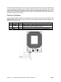
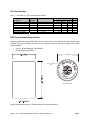
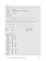
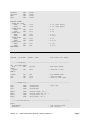
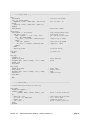
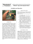
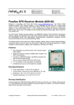
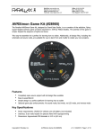
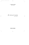
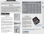
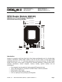
599 Menlo Drive, Suite 100
Rocklin, California 95765, USA
Office: (916) 624-8333
Fax: (916) 624-8003
General: [email protected]
Technical: [email protected]
Web Site: www.parallax.com
Educational: www.stampsinclass.com
RFID Reader Module (#28140)
RFID 54 mm x 85 mm Rectangle Tag (#28141)
RFID 50 mm Round Tag (#28142)
2.45” (62.2mm)
3.25” (82.5mm)
VCC
/ENABLE
SOUT
GND
idea studio
2.95” (75mm)
2.15” (54.5mm)
0.14” (3.6mm)
0.1” (2.5mm)
Introduction
Designed in cooperation with Grand Idea Studio (http://www.grandideastudio.com/), the Parallax Radio
Frequency Identification (RFID) Reader Module is the first low-cost solution to read passive RFID
transponder tags up to 1 ¾” - 3” inches away depending on the tag (see list below). The RFID Reader
Module can be used in a wide variety of hobbyist and commercial applications, including access control,
automatic identification, robotics navigation, inventory tracking, payment systems, and car
immobilization.
•
•
•
•
•
Fully-integrated, low-cost method of reading passive RFID transponder tags
1-wire, 2400 baud Serial TTL interface to PC, BASIC Stamp® and other processors
Requires single +5VDC supply
Bi-color LED for visual indication of activity
0.100” pin spacing for easy prototyping and integration
Parallax, Inc. • RFID Reader Module (#28140) •Updated 09/2005 v1.1
Page 1
The Parallax RFID Reader Module works exclusively with the EM Microelectronics-Marin SA EM4100-family
of passive read-only transponder tags. A variety of different tag types and styles exist with the most
popular made available from Parallax. Each transponder tag contains a unique identifier (one of 240, or
1,099,511,627,776, possible combinations) that is read by the RFID Reader Module and transmitted to
the host via a simple serial interface.
Electronic Connections
The Parallax RFID Reader Module can be integrated into any design using only four connections (VCC,
/ENABLE, SOUT, GND). Use the following circuit for connecting the Parallax RFID Reader Module to the
BASIC Stamp microcontroller:
Pin
1
2
Pin Name
VCC
/ENABLE
Type
P
I
Function
System power, +5V DC input.
Module enable pin. Active LOW digital input. Bring this pin LOW to
enable the RFID reader and activate the antenna.
3
SOUT
O
Serial Out. TTL-level interface, 2400bps, 8 data bits, no parity, 1 stop bit.
4
GND
G
System ground. Connect to power supply’s ground (GND) terminal.
Note: Type: I = Input, O = Output, P = Power, G = Ground
Parallax, Inc. • RFID Reader Module (#28140) •Updated 09/2005 v1.1
Page 2
Communication Protocol
Implementation and usage of the RFID Reader Module is straightforward. BASIC Stamp 1, 2, and
SX28AC/DP code examples (SX/B) are included at the end of this documentation.
The RFID Reader Module is controlled with a single TTL-level active-low /ENABLE pin. When the /ENABLE
pin is pulled LOW, the module will enter its active state and enable the antenna to interrogate for tags.
The current consumption of the module will increase dramatically when the module is active.
A visual indication of the state of the RFID Reader Module is given with the on-board LED. When the
module is successfully powered-up and is in an idle state, the LED will be GREEN. When the module is in
an active state and the antenna is transmitting, the LED will be RED.
The face of the RFID tag should be held parallel to the front or back face of the antenna (where the
majority of RF energy is focused). If the tag is held sideways (perpendicular to the antenna) you'll either
get no reading or a poor reading. Only one transponder tag should be held up to the antenna at any
time. The use of multiple tags at one time will cause tag collisions and confuse the reader. The two tags
available in the Parallax store have a read distance of approximately 3 inches. Actual distance may vary
slightly depending on the size of the transponder tag and environmental conditions of the application.
When a valid RFID transponder tag is placed within range of the activated reader, the unique ID will be
transmitted as a 12-byte ASCII string via the TTL-level SOUT (Serial Output) pin in the following format:
MSB
Start Byte
(0x0A)
LSB
Unique ID
Digit 1
Unique ID
Digit 2
Unique ID
Digit 3
Unique ID
Digit 4
Unique ID
Digit 5
Unique ID
Digit 6
Unique ID
Digit 7
Unique ID
Digit 8
Unique ID
Digit 9
Unique ID
Digit 10
Stop Byte
(0x0D)
The start byte and stop byte are used to easily identify that a correct string has been received from the
reader (they correspond to a line feed and carriage return characters, respectively). The middle ten bytes
are the actual tag's unique ID.
All communication is 8 data bits, no parity, 1 stop bit, non-inverted, least significant bit first (8N1). The
baud rate is configured for 2400bps, a standard communications speed supported by most any
microprocessor or PC, and cannot be changed. The Parallax RFID Reader Module initiates all
communication. The Parallax RFID Reader Module can connect directly to any TTL-compatible UART or to
an RS232-compatible interface by using an external level shifter.
Absolute Maximum Ratings and Electrical Characteristics
Condition
Operating Temperature
Storage Temperature
Supply Voltage (VCC)
Ground Voltage (VSS)
Voltage on any pin with respect to VSS
Value
-40ºC to +85ºC
-55ºC to +125ºC
+4.5V to +5.5V
0V
-0.3V to +7.0V
Stresses above those listed under “Absolute Maximum Ratings” may cause permanent damage to the
device. This is a stress rating only and functional operation of the device at those or any other conditions
above those indicated in the operation listings of this specification is not implied. Exposure to maximum
rating conditions for extended periods may affect device reliability.
Parallax, Inc. • RFID Reader Module (#28140) •Updated 09/2005 v1.1
Page 3
DC Characteristics
At VCC = +5.0V and TA = 25ºC unless otherwise noted
Parameter
Supply Voltage
Supply Current, Idle
Supply Current, Active
Input LOW voltage
Input HIGH voltage
Output LOW voltage
Output HIGH voltage
Symbol
VCC
IIDLE
ICC
VIL
VIH
VOL
VOH
Test
Conditions
------+4.5V <= VCC <= +5.5V
+4.5V <= VCC <= +5.5V
VCC = +4.5V
VCC = +4.5V
Specification
Min.
Typ.
Max.
4.5
5.0
5.5
--10
----90
------0.8
2.0
--------0.6
VCC - 0.7
-----
Unit
V
mA
mA
V
V
V
V
RFID Tags Available From Parallax
Parallax provides two passive RFID tags from our on-line store. We’re stocking the tags because many
suppliers have high minimums, yet many of our customers may only want a few tags for their basic
experimentation.
•
•
54 mm x 85 mm Rectangle Tag (#28141)
50 mm Round Tag (#28142)
1.97” (50mm)
dI
qu e
ndu
nd
t ic
an
po
ni
U
ID - L o g i s
er
RF
G
TA
r
Wo ld
Ø.17” (4.3mm)
hole
r an
s t r i al T
s
0.8” (2.1mm) thick
Actual tag dimensions may vary. Contact Parallax for specific information.
Parallax, Inc. • RFID Reader Module (#28140) •Updated 09/2005 v1.1
Page 4
Optional Tag Information
Even though Parallax only carries a Round Tag and a Rectangle Tag the following values were obtained
from different tags available in the market.
ISO Card:
World Tag 50mm:
World Tag 30mm:
Bobsleigh Keyfob:
Tear shape:
Wristband:
6.3cm
6.8cm
5.3cm
5.3cm
4.0cm
4.0cm
(2.5") +/(2.7") +/(2.1") +/(2.1") +/(1.6") +/(1.6") +/-
10%
10%
10%
10%
10%
10%
RFID Technology Overview
Material in this section is based on information provided by the RFID Journal (www.rfidjournal.com).
Radio Frequency Identification (RFID) is a generic term for non-contacting technologies that use radio
waves to automatically identify people or objects. There are several methods of identification, but the
most common is to store a unique serial number that identifies a person or object on a microchip that is
attached to an antenna. The combined antenna and microchip are called an "RFID transponder" or "RFID
tag" and work in combination with an "RFID reader" (sometimes called an "RFID interrogator").
An RFID system consists of a reader and one or more tags. The reader's antenna is used to transmit
radio frequency (RF) energy. Depending on the tag type, the energy is "harvested" by the tag's antenna
and used to power up the internal circuitry of the tag. The tag will then modulate the electromagnetic
waves generated by the reader in order to transmit its data back to the reader. The reader receives the
modulated waves and converts them into digital data. In the case of the Parallax RFID Reader Module,
correctly received digital data is sent serially through the SOUT pin.
There are two major types of tag technologies. "Passive tags" are tags that do not contain their own
power source or transmitter. When radio waves from the reader reach the chip’s antenna, the energy is
converted by the antenna into electricity that can power up the microchip in the tag (known as "parasitic
power"). The tag is then able to send back any information stored on the tag by reflecting the
electromagnetic waves as described above. "Active tags" have their own power source and transmitter.
The power source, usually a battery, is used to run the microchip's circuitry and to broadcast a signal to a
reader. Due to the fact that passive tags do not have their own transmitter and must reflect their signal
to the reader, the reading distance is much shorter than with active tags. However, active tags are
typically larger, more expensive, and require occasional service. The RFID Reader Module is designed
specifically for low-frequency (170 kHz) passive tags.
Frequency refers to the size of the radio waves used to communicate between the RFID system
components. Just as you tune your radio to different frequencies in order to hear different radio stations,
RFID tags and readers have to be tuned to the same frequency in order to communicate effectively. RFID
systems typically use one of the following frequency ranges: low frequency (or LF, around 170 kHz), high
frequency (or HF, around 13.56 MHz), ultra-high frequency (or UHF, around 868 and 928 MHz), or
microwave (around 2.45 and 5.8 GHz). It is generally safe to assume that a higher frequency equates to
a faster data transfer rate and longer read ranges, but also more sensitivity to environmental factors such
as liquid and metal that can interfere with radio waves.
There really is no such thing as a "typical" RFID tag. The read range of a tag ultimately depends on many
factors: the frequency of RFID system operation, the power of the reader, and interference from other RF
devices. Balancing a number of engineering trade-offs (antenna size v. reading distance v. power v.
Parallax, Inc. • RFID Reader Module (#28140) •Updated 09/2005 v1.1
Page 5
manufacturing cost), the Parallax RFID Reader Module's antenna was designed with a specific inductance
and "Q" factor for 170kHz RFID operation at a tag read distance of up to 1 ¾” - 3” inches.
Example Code
The following code examples read tags from a RFID Reader Module and compare the values to known
tags (stored in an EEPROM table).
' =========================================================================
'
'
File....... RFID.BS1
'
Purpose.... RFID Tag Reader / Simple Security System
'
Author..... (c) Parallax, Inc. -- All Rights Reserved
'
E-mail..... [email protected]
'
Started....
'
Updated.... 07 FEB 2005
'
'
{$STAMP BS1}
'
{$PBASIC 1.0}
'
' =========================================================================
' -----[ Program Description ]--------------------------------------------'
' Reads tags from a Parallax RFID reader and compares to known tags (stored
' in EEPROM table). If tag is found, the program will disable a lock.
' -----[ Revision History ]------------------------------------------------
' -----[ I/O Definitions ]------------------------------------------------SYMBOL
SYMBOL
SYMBOL
SYMBOL
Enable
RX
Spkr
Latch
=
=
=
=
0
1
2
3
'
'
'
'
low = reader on
serial from reader
speaker output
lock/latch control
' -----[ Constants ]------------------------------------------------------SYMBOL
LastTag
= 2
' 3 tags; 0 to 2
' -----[ Variables ]------------------------------------------------------SYMBOL
SYMBOL
SYMBOL
SYMBOL
SYMBOL
SYMBOL
SYMBOL
SYMBOL
SYMBOL
SYMBOL
tag0
tag1
tag2
tag3
tag4
tag5
tag6
tag7
tag8
tag9
=
=
=
=
=
=
=
=
=
=
B0
B1
B2
B3
B4
B5
B6
B7
B8
B9
SYMBOL
SYMBOL
SYMBOL
tagNum
pntr
char
= B10
= B11
= B12
' RFID bytes buffer
' from EEPROM table
' pointer to char in table
' character from table
Parallax, Inc. • RFID Reader Module (#28140) •Updated 09/2005 v1.1
Page 6
' -----[ EEPROM Data ]----------------------------------------------------Tags:
EEPROM
EEPROM
EEPROM
EEPROM
EEPROM
("0F0184F20B")
("0F01D9D263")
("04129C1B43")
("0000000000")
("0000000000")
' valid tags
' space for other tags
' -----[ Initialization ]-------------------------------------------------Reset:
HIGH Enable
LOW Latch
' turn of RFID reader
' lock the door!
' -----[ Program Code ]---------------------------------------------------Main:
LOW Enable
'
SERIN RX, T2400, ($0A)
'
SERIN RX, T2400, tag0, tag1, tag2, tag3, tag4 '
SERIN RX, T2400, tag5, tag6, tag7, tag8, tag9
HIGH Enable
'
Check_List:
FOR tagNum = 0 TO
pntr = tagNum *
IF char <> tag0
pntr = tagNum *
IF char <> tag1
pntr = tagNum *
IF char <> tag2
pntr = tagNum *
IF char <> tag3
pntr = tagNum *
IF char <> tag4
pntr = tagNum *
IF char <> tag5
pntr = tagNum *
IF char <> tag6
pntr = tagNum *
IF char <> tag7
pntr = tagNum *
IF char <> tag8
pntr = tagNum *
IF char <> tag9
GOTO Tag_Found
Bad_Char:
NEXT
LastTag
10 + 0 : READ
THEN Bad_Char
10 + 1 : READ
THEN Bad_Char
10 + 2 : READ
THEN Bad_Char
10 + 3 : READ
THEN Bad_Char
10 + 4 : READ
THEN Bad_Char
10 + 5 : READ
THEN Bad_Char
10 + 6 : READ
THEN Bad_Char
10 + 7 : READ
THEN Bad_Char
10 + 8 : READ
THEN Bad_Char
10 + 9 : READ
THEN Bad_Char
Bad_Tag:
SOUND Spkr, (25, 80)
PAUSE 1000
GOTO Main
Tag_Found:
DEBUG #tagNum, CR
HIGH Latch
SOUND Spkr, (114, 165)
LOW Latch
pntr, char
activate the reader
wait for header
get tag bytes
deactivate reader
' scan through known tags
' read char from DB
' compare with tag data
pntr, char
pntr, char
pntr, char
pntr, char
pntr, char
pntr, char
pntr, char
pntr, char
pntr, char
' all match -- good tag
' groan
'
'
'
'
for testing
remove latch
beep
restore latch
Parallax, Inc. • RFID Reader Module (#28140) •Updated 09/2005 v1.1
Page 7
GOTO Main
END
' =========================================================================
'
'
File....... RFID.BS2
'
Purpose.... RFID Tag Reader / Simple Security System
'
Author..... (c) Parallax, Inc. -- All Rights Reserved
'
E-mail..... [email protected]
'
Started....
'
Updated.... 07 FEB 2005
'
'
{$STAMP BS2}
'
{$PBASIC 2.5}
'
' =========================================================================
' -----[ Program Description ]--------------------------------------------'
' Reads tags from a Parallax RFID reader and compares to known tags (stored
' in EEPROM table). If tag is found, the program will disable a lock.
' -----[ Revision History ]------------------------------------------------
' -----[ I/O Definitions ]------------------------------------------------Enable
RX
Spkr
Latch
PIN
PIN
PIN
PIN
0
1
2
3
'
'
'
'
low = reader on
serial from reader
speaker output
lock/latch control
' -----[ Constants ]------------------------------------------------------#SELECT $STAMP
#CASE BS2, BS2E, BS2PE
T1200
CON
813
T2400
CON
396
T4800
CON
188
T9600
CON
84
T19K2
CON
32
TMidi
CON
12
T38K4
CON
6
#CASE BS2SX, BS2P
T1200
CON
2063
T2400
CON
1021
T4800
CON
500
T9600
CON
240
T19K2
CON
110
TMidi
CON
60
T38K4
CON
45
#CASE BS2PX
T1200
CON
3313
T2400
CON
1646
T4800
CON
813
T9600
CON
396
T19K2
CON
188
TMidi
CON
108
T38K4
CON
84
#ENDSELECT
Parallax, Inc. • RFID Reader Module (#28140) •Updated 09/2005 v1.1
Page 8
SevenBit
Inverted
Open
Baud
CON
CON
CON
CON
#SELECT $STAMP
#CASE BS2, BS2E
TmAdj
CON
FrAdj
CON
#CASE BS2SX
TmAdj
CON
FrAdj
CON
#CASE BS2P
TmAdj
CON
FrAdj
CON
#CASE BS2PE
TmAdj
CON
FrAdj
CON
#CASE BS2Px
TmAdj
CON
FrAdj
CON
#ENDSELECT
LastTag
CON
$2000
$4000
$8000
T2400
$100
$100
' x 1.0 (time adjust)
' x 1.0 (freq adjust)
$280
$066
' x 2.5
' x 0.4
$3C5
$044
' x 3.77
' x 0.265
$100
$0AA
' x 1.0
' x 0.665
$607
$2A
' x 6.03
' x 0.166
3
#DEFINE __No_SPRAM = ($STAMP < BS2P)
' does module have SPRAM?
' -----[ Variables ]------------------------------------------------------#IF __No_SPRAM #THEN
buf
VAR
#ELSE
chkChar
VAR
#ENDIF
tagNum
idx
char
VAR
VAR
VAR
Byte(10)
' RFID bytes buffer
Byte
' character to test
Nib
Byte
Byte
' from EEPROM table
' tag byte index
' character from table
' -----[ EEPROM Data ]----------------------------------------------------Tag1
Tag2
Tag3
DATA
DATA
DATA
"0F0184F20B"
"0F01D9D263"
"04129C1B43"
Name0
Name1
Name2
Name3
DATA
DATA
DATA
DATA
"Unauthorized", CR, 0
"George Johnston", CR, 0
"Dick Miller", CR, 0
"Mary Evans", CR, 0
' valid tags
' -----[ Initialization ]-------------------------------------------------Reset:
HIGH Enable
LOW Latch
' turn of RFID reader
' lock the door!
Parallax, Inc. • RFID Reader Module (#28140) •Updated 09/2005 v1.1
Page 9
' -----[ Program Code ]---------------------------------------------------Main:
LOW Enable
#IF __No_SPRAM #THEN
SERIN RX, T2400, [WAIT($0A), STR buf\10]
#ELSE
SERIN RX, T2400, [WAIT($0A), SPSTR 10]
#ENDIF
HIGH Enable
Check_List:
FOR tagNum = 1 TO LastTag
FOR idx = 0 TO 9
READ (tagNum - 1 * 10 + idx), char
#IF __No_SPRAM #THEN
IF (char <> buf(idx)) THEN Bad_Char
#ELSE
GET idx, chkChar
IF (char <> chkChar) THEN Bad_Char
#ENDIF
NEXT
GOTO Tag_Found
Bad_Char:
NEXT
' activate the reader
' wait for hdr + ID
' deactivate reader
' scan through known tags
' scan bytes in tag
' get tag data from table
' compare tag to table
' read char from SPRAM
' compare to table
' all bytes match!
' try next tag
Bad_Tag:
tagNum = 0
GOSUB Show_Name
FREQOUT Spkr, 1000 */ TmAdj, 115 */ FrAdj
PAUSE 1000
GOTO Main
' print message
' groan
Tag_Found:
GOSUB Show_Name
HIGH Latch
FREQOUT Spkr, 2000 */ TmAdj, 880 */ FrAdj
LOW Latch
GOTO Main
'
'
'
'
print name
remove latch
beep
restore latch
END
' -----[ Subroutines ]----------------------------------------------------' Prints name associated with RFID tag
Show_Name:
DEBUG DEC tagNum, ": "
LOOKUP tagNum,
[Name0, Name1, Name2, Name3], idx
DO
READ idx, char
IF (char = 0) THEN EXIT
DEBUG char
idx = idx + 1
LOOP
RETURN
' point to first character
'
'
'
'
read character from name
if 0, we're done
otherwise print it
point to next character
Parallax, Inc. • RFID Reader Module (#28140) •Updated 09/2005 v1.1
Page 10