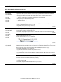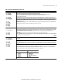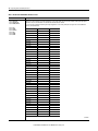
1
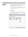
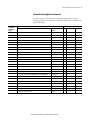
Release Notes
CompactLogix 5370 Controllers, Revision 21
Catalog Numbers
1769-L16ER-BB1B, 1769-L18ER-BB1B, 1769-L18ERM-BB1B
1769-L24ER-QB1B, 1769-L24ER-QBFC1B, 1769-L27ERM-QBFC1B
1769-L30ER, 1769-L30ER-NSE, 1769-L30ERM, 1769-L33ER, 1769-L33ERM, 1769-L36ERM
Topic
Page
Compatible Software Versions
2
Before You Begin
3
Enhancements
4
Corrected Anomalies
5
Known Anomalies
12
Restrictions
15
Install the Controller Revision
19
Additional Resources
22
IMPORTANT
Consider the following before upgrading the firmware on your controller:
• Firmware release notes contain material for all minor revisions subsequent to each
major revision.
Before updating your controller, we strongly recommend that you review
information pertinent to previous major firmware revisions. For example, when
updating from revision 20.xxx to 21.xxx, view information in the following
publications:
- CompactLogix™ 5370 L1 Controllers, Revision 20 Release Notes,
publication 1769-RN023
- CompactLogix 5370 L2 Controllers, Revision 20 Release Notes,
publication 1769-RN024
- CompactLogix 5370 L3 Controllers, Revision 20 Release Notes,
publication 1769-RN020
Release notes are available at: http://www.rockwellautomation.com/literature.
• After upgrading the firmware on your module, we strongly recommend that you
retest and/or validate your application offline before going online.
2 CompactLogix 5370 Controllers, Revision 21
Compatible Software Versions
To use firmware revision 21.011, these minimum software versions are required.
Table 1 - Compatible Software Versions
Software
Required Software Version, Min.
Compare Tool
3.40.00
ControlFLASH™
12.00.00
FactoryTalk® AssetCentre
4.00.00 (CPR 9, SR3)
FactoryTalk Services Platform
2.50.00 (CPR 9, SR5.1)
FactoryTalk Activation
3.51.00 (CPR 9, SR5.1)
RSLinx® Classic
3.51.01 (CPR 9, SR5.1)
RSLinx Enterprise
5.51.00 (CPR 9, SR5.1)
Studio 5000™ Logix Designer
21.00.00 (CPR9, SR5.1)
RSNetWorx™ for ControlNet
21.00.00 (CPR 9, SR5.1)
RSNetWorx for DeviceNet
RSNetWorx for EtherNet/IP
Operating system and service pack compatibility are as follows:
• Microsoft Windows 7 Professional (64-bit) with Service Pack 1
• Microsoft Windows 7 Home Premium (64-bit) with Service Pack 1
• Microsoft Windows 7 Home Premium (32-bit) with Service Pack 1
• Microsoft Windows Server 2008 R2 Standard Edition with Service Pack 1
For hardware requirements, go to
http://www.rockwellautomation.com/rockwellsoftware/design/rslogix5000/sys
req.html.
Rockwell Automation Publication 1769-RN025A-EN-P - January 2013
CompactLogix 5370 Controllers, Revision 21 3
Before You Begin
Before you upgrade your firmware, consider the following.
IMPORTANT
Loss of communication or power during a controller firmware upgrade can result in the
controller rejecting the new firmware. Upon the rejection of new firmware, the
controller reverts to the out-of-the-box firmware revision:
• If the controller firmware upgrade fails and the OK status indicator flashes red, take
these corrective actions:
– Cycle controller power and attempt the firmware upgrade again.
– If, after attempting another upgrade, the controller’s OK status indicator
continues to flash red, cycle power and attempt another firmware upgrade.
– If repeated attempts to upgrade the controller firmware continue to result in
the OK status indicator flashing red, contact Rockwell Automation® Technical
Support.
• If the controller firmware upgrade fails and the OK status indicator is solid red,
contact Rockwell Automation Technical Support.
These preliminary actions are required before using your controller.
Table 2 - Before You Begin
If
Then
You are updating a controller
Before you begin updating your controller, check the status of your Secure Digital
(SD) card.
If your SD card is
Then
Unlocked
You can successfully upgrade the firmware to the
intended revision.
Locked and the Load
Image option is set to
On Power Up
You should complete these steps before beginning
the upgrade:
• Unlock the SD card.
• Change the Load Image option to User
Initiated.
If the card is locked when you attempt to upgrade
the firmware, the upgrade fails and the controller
reverts to the firmware revision already stored on
the SD card.
Unlocked
Position
Rockwell Automation Publication 1769-RN025A-EN-P - January 2013
Locked
Position
4 CompactLogix 5370 Controllers, Revision 21
These enhancements are available when firmware revision 21.011 is used with
Logix Designer application, version 21.00.00 or later.
Enhancements
Table 3 - Enhancements with Firmware Revision 21.011
Cat. No.
Description
1769-L16ER-BB1B,
1769-L18ER-BB1B,
1769-L18ERM-BB1B
Pre-scan of Add-On Instruction Behavior
The Pre-scan behavior of Add-On Instructions has been enhanced. This enhancement can affect Pre-scan behavior of Add-On Instructions when
indirect addressing is used.
This enhancement can improve the Add-On Instruction initialization behavior when indirect addressing is used.
For more information, see Rockwell Automation Knowledgebase document 481124.
You can access the Rockwell Automation Knowledgebase at:
http://www.rockwellautomation.com/rockwellautomation/support/overview.page?
1769-L24ER-QB1B,
1769-L24ER-QBFC1B,
1769-L27ERM-QBFC1B
1769-L30ER,
1769-L30ERM,
1769-L30ER-NSE,
1769-L33ER,
1769-L33ERM,
1769-L36ERM
HMI Connectivity and Performance Improvements
HMI communication drivers can perform Rockwell Automation-approved symbolic data reads. Symbolic reads improve the read performance
and eliminate errors being returned when the HMI attempts to collect data.
For more information, see the Logix5000™ Data Access Programming Manual, publication 1756-PM020.
Introducing the Studio 5000 Logix Designer Application
The version 21 release re-brands RSLogix™ 5000 software to Logix Designer application and embeds the application as a key component of the
Studio 5000 environment.
The Studio 5000 environment is the new launch point for components of the Integrated Architecture. The Studio 5000 environment provides the
infrastructure to accomplish the following between traditionally independent automation development tasks:
• Share data
• Share design time components
• Share runtime components
Extended Tag Properties
You can use Extended Properties to define additional information about a tag or structure of tags.
The Logix Designer application, version 21 or later, provides the option to specify Engineering Units and Min/Max Values for numeric tags,
Engineering Units and state information for Boolean tags.
Extended properties are also available for user defined data types, arrays, or other complex data structures.
Project Documentation Stored in Controller
The Logix Designer application, version 21, provides the option to store all of your project documentation, including comments, tag descriptions,
and other key descriptors of the project in the controller.
Other project descriptions can be stored online, such as routine descriptions and task descriptions.
Uploading a project now restores all of the original project documentation without having to find the original ACD file.
1769-L18ERM-BB1B
1769-L27ERM-QBFC1B
Motion Axis Output Cam Expansion
This enhancement applies to applications that use any Motion type.
The Motion Axis Output Cam (MAOC) instruction now supports additional devices for scheduling. Up to 16 scheduled outputs are now supported.
1769-L30ERM,
1769-L33ERM,
1769-L36ERM
1769-L24ER-QB1B,
1769-L24ER-QBFC1B,
1769-L27ERM-QBFC1B
1769-L30ER,
1769-L30ERM,
1769-L30ER-NSE,
1769-L33ER,
1769-L33ERM,
1769-L36ERM
1769-L16ER-BB1B,
1769-L18ER-BB1B,
1769-L18ERM-BB1B
The local 1769-CompactBus module overlap minor fault behavior has changed. In RSLogix 5000 software, version 20, when a module overlap
minor fault was detected one minor fault was logged and no others would be logged again until the minor fault was cleared.
In the Logix Designer application, version 21, all instances of module overlap minor faults are logged, regardless if one has been previously
logged. The faults continue to be logged until you clear the faults or the faults no longer exist.
After a connection is establishing to a 1769-CompactBus module, the software does not log any module overlap minor faults for the
approximately 30 seconds.
The controller supports the use of an Event task with its embedded input points. You can configure embedded input-point terminals to trigger
an Event task if a change of state (COS) occurs.
Rockwell Automation Publication 1769-RN025A-EN-P - January 2013
CompactLogix 5370 Controllers, Revision 21 5
These anomalies have been corrected with firmware revision 21.011.
Corrected Anomalies
Table 4 - Corrected Anomalies with Firmware Revision 21.011
Cat. No.
Description
1769-L16ER-BB1B,
1769-L18ER-BB1B,
1769-L18ERM-BB1B
CORRECTED: When using the Automatic Device Configuration (ADC) feature, the Logix controller ‘owns’ the configuration in the drive. Do not
use the HMI or other external tools, such as DriveExplorer™ software, to change drive parameters. Doing so may cause a sequence of events to
occur that results in the connection between the controller and the drive to be dropped, and causes the controller to be unable to re-establish
the connection.
Consider using the Write Mask function (drive Parameter 888 - [Write Mask Cfg]) to prevent tools connected to ports other than the Embedded
EtherNet/IP port, from writing to the drive.
This anomaly was addressed with Drive firmware revision 4.001.
00129165
1769-L24ER-QB1B,
1769-L24ER-QBFC1B,
1769-L27ERM-QBFC1B
1769-L30ER,
1769-L30ERM,
1769-L30ER-NSE,
1769-L33ER,
1769-L33ERM,
1769-L36ERM
CORRECTED: Your controller might experience a major nonrecoverable fault if it uses an RSLogix 5000 project that requires most of the
controller’s available memory and power is cycled to the controller.
If the RSLogix 5000 project is so large that fewer than 25,000 bytes of controller memory remain free before power is cycled, the controller might
experience this anomaly.
Complete these steps to best determine how much controller memory the project uses.
1. If your controller is online, go offline.
2. Download the RSLogix 5000 project to the controller.
3. Cycle through all screens on each HMI device used in the application.
Often, the inclusion of HMI devices, such as PanelView™ Plus terminals, in the project causes it to use a large portion of the controller’s
memory.
4. Go online with the controller.
5. Access the Memory tab on the Controller Properties dialog box:
– If your controller has 25,000 or more bytes of memory free, it should not experience this anomaly.
– If your controller has fewer than 25,000 bytes of memory free, it is more likely to experience this anomaly after the next power cycle on
the controller.
If this anomaly occurs, clear the fault and download the project.
00126637
CORRECTED: When the following conditions exist in your CompactLogix 5370 control system, the controller may log a major recoverable fault,
Type 2/Code 23:
• The control system includes remote POINT I/O™ modules over an EtherNet/IP network.
• Any of the POINT I/O modules are configured to Major Fault On Controller if Connection Fails While in Run Mode.
• A power cycle occurs on the controller.
To work around this anomaly, do not configure any remote POINT I/O modules over an EtherNet/IP network to Major Fault On Controller if
Connection Fails While in Run Mode.
00129095
CORRECTED: When using a 1747-AENTR SLC™ 500 EtherNet/IP Adapter and more than five modules in a remote SLC chassis connected to your
CompactLogix 5370 controller, the second download of a project to your controller causes the controller to lose communication with the remote
SLC chassis.
After losing communication with the remote SLC chassis, you also cannot communicate with the controller via the USB or Ethernet port. You
must disconnect the Ethernet cable from the 1747-AENTR adapter.
After the Ethernet cable is disconnected from the 1747-AENTR adapter, you can re-establish communication to the controller. However, the
controller contains no program at that point.
You must re-download the program to the controller and then reconnect the Ethernet cable to the 1747-AENTR adapter to resume normal
operations.
00128819
CORRECTED: Changes made to the Buffer Timeout value for FactoryTalk Alarms and Events subscribers do not take effect until the existing
buffer is deleted.
The FactoryTalk alarm buffer (stored in Logix controller memory) is designed to persist through power cycles. If you change the Buffer Timeout
value (via the Communication Setup dialog box in FactoryTalk View Studio SE software), the controller does not use the new timeout value until
the existing buffer is deleted and then recreated. To force recreation of this buffer, do one of the following:
• Redownload the project to the controller.
• Disconnect the FactoryTalk Alarms and Events subscriber and leave it disconnected until the existing timeout expires.
00069461
Rockwell Automation Publication 1769-RN025A-EN-P - January 2013
6 CompactLogix 5370 Controllers, Revision 21
Table 4 - Corrected Anomalies with Firmware Revision 21.011
Cat. No.
Description
1769-L16ER-BB1B,
1769-L18ER-BB1B,
1769-L18ERM-BB1B
CORRECTED: The MinDurationPRE and MinDurationACC members of ALMD and ALMA tags are defined as DINT (signed double integer) but they
are treated as UDINT (unsigned double integer) by Logix firmware. This causes negative values of the tag members to be handled as large
positive numbers when they should be handled as zero.
119996
1769-L24ER-QB1B,
1769-L24ER-QBFC1B,
1769-L27ERM-QBFC1B
CORRECTED: In SFCs, when using time-limited actions in steps, if the program stays on a given step for greater than 24 days (2**32 ms) the
timer’s accumulator (ACC) will roll over and the action body starts to execute again.
The time-limited action initializes its timer when it starts (step is first scanned). On subsequent scans, it compares the timers PRE and ACC value.
If ACC<PRE, the action body will execute. If ACC >=PRE, it is not executed. When the rollover occurs, the ACC, PRE and action body will execute
again when it should not.
00124697
1769-L30ER,
1769-L30ERM,
1769-L30ER-NSE,
1769-L33ER,
1769-L33ERM,
1769-L36ERM
CORRECTED: The controller supports only three active reconfigure messages at a time. If more than three are triggered at a time, they will
complete (DN bit will go high), but not all the modules will be reconfigured.
For example, if you send five reconfiguration messages at the same time, three reconfigure messages will truly complete (DN bit will go high),
and the I/O modules will be reconfigured. The other two reconfigure messages will indicate complete (DN bit will go high), but the I/O modules
will not be reconfigured. In this case, the last two should have errored (ER bit), but do not.
00125204
CORRECTED: Log On to FactoryTalk Dialog Box Displays When Launching RSLogix 5000 Software
When launching RSLogix 5000 software, the Log On to FactoryTalk dialog box may be displayed. This dialog box may be seen when you do not
have Administrator privileges on the personal computer and the current user does not exist in the FactoryTalk directory. If this dialog box is
cancelled, the RSLogix 5000 software will not be launched. When the dialog box is displayed, entering the credentials for a user that has
Administrator privileges on the personal computer will then allow RSLogix 5000 software to be launched.
To avoid seeing this dialog box, you can add the current user or user group to the FactoryTalk directory. Follow these steps to add a user or user
group to the FactoryTalk directory.
1. Launch the FactoryTalk Administration Console (available from the Start menu).
2. Select the Network directory when prompted.
(You may need to provide credentials for a user with Administrator privileges in order to continue.)
3. To allow access for a particular user, navigate to Network\System\Users and Groups\Users, right-click the Users folder and choose
New>Windows Linked User.
4. Click Add and provide the domain\logon name for the desired user.
(You can click Check Names to verify that the name was found.)
5. To allow access for all authenticated users, navigate to Network\System\Users and Groups\User Groups, right-click the User Groups folder and
choose New>Windows Linked User Group.
6. Click Add and type the name of the user group, Authenticated Users.
The Log On to FactoryTalk dialog box may also display when using Remote Desktop to connect to the personal computer running RSLogix 5000
software. This is due to FactoryTalk Security not recognizing the computer name. To enable access through Remote Desktop for a specific
computer, you should add the name of the computer initiating the Remote Desktop connection to the Network\System\Computers and
Groups\Computers folder in the FactoryTalk Administration Console.
To allow all computers to connect, follow these steps.
1. Open the FactoryTalk Administration Console and log in to the Network directory using your domain credentials.
2. Navigate to Network\System\Security Policy. In the Computer Policy Settings section, set Identify terminal server clients using the name of to
Server Computer.
Important: If Use Single Sign-on is set to disable in FactoryTalk software, then the Log On to FactoryTalk dialog box will be displayed each time
RSLogix 5000 software is launched and proper user credentials must be entered in order to continue. (By default, ‘Use Single Sign-on’ is set to
enable.)
00124955
CORRECTED: Your controller can experience a Module RPI Overlap minor fault (Type 03/Code 94) when you perform any of the following
actions:
• Download an RSLogix 5000 project to the controller.
Typically, a project download results in this anomaly if the project includes modules with large I/O sizes, such as a 1769-SDN scanner module,
or high numbers of I/O modules.
• While the controller is online, you attempt to change the RPI value for an I/O module.
• While the controller is online, you attempt to inhibit and then uninhibit an I/O connection.
When your controller experiences a Module RPI Overlap minor fault as a result of these actions, use the Controller Properties dialog box to clear
the fault.
00125049
Rockwell Automation Publication 1769-RN025A-EN-P - January 2013
CompactLogix 5370 Controllers, Revision 21 7
Table 4 - Corrected Anomalies with Firmware Revision 21.011
Cat. No.
Description
1769-L16ER-BB1B,
1769-L18ER-BB1B,
1769-L18ERM-BB1B
CORRECTED: The controller’s Ethernet port settings, for example, the IP address or Subnet Mask, are always loaded from the SD card regardless
of the Load Image parameter configuration on the Nonvolatile Memory Load/Store dialog box.
00126022
1769-L24ER-QB1B,
1769-L24ER-QBFC1B,
1769-L27ERM-QBFC1B
CORRECTED: When modifying the controller’s Ethernet configuration with RSLinx Classic software, version 2.59.00 or earlier, you may
experience a Module Configuration Invalid: Parameter error (16#0009).
This anomaly occurs if you try to apply two network configuration changes without closing the Controller Properties dialog box between
the changes.
To work around this anomaly, close the Controller Properties dialog box after making every Ethernet configuration change in RSLinx
Classic software.
IMPORTANT: This anomaly is corrected in RSLinx Classic software, version 3.51.00 or later.
00126023
1769-L30ER,
1769-L30ERM,
1769-L30ER-NSE,
1769-L33ER,
1769-L33ERM,
1769-L36ERM
CORRECTED: The controller does not correctly display the active ring supervisor on the Ring Statistics webpage available from the
Diagnostics folder.
The webpage displays the active ring supervisor IP address in reverse order. For example, an active ring supervisor using an IP address of
192.168.1.4 appears on the Ring Statistics webpage as 4.1.168.192.
00125647
CORRECTED: The RSLogix 5000 Clock Update tool does not support Windows 7 or Windows Server 2008 operating system.
CORRECTED: In RSLogix 5000 software, version 20 and earlier, the Audit Mask Value is not saved as part of the user application. Consequently,
when a restore from removable media, that is, an SD card, is performed, the value is restored to its default value.
In Logix Designer application, version 21 and later, the Audit Mask Value is saved with the user application.
00135562
CORRECTED: When using PowerFlex 750 series drives with firmware that supports Drives Automatic Device Configuration (ADC) on powerup,
the controller can become stuck in the transition to Run mode. When stuck in the transition to Run mode, the application is not executing and
the outputs are not being updated.
For more information, see Rockwell Automation Knowledgebase document 493802.
You can access the Rockwell Automation Knowledgebase at:
http://www.rockwellautomation.com/rockwellautomation/support/overview.page?
00134308
1769-L18ERM-BB1B
1769-L27ERM-QBFC1B
1769-L30ERM,
1769-L33ERM,
1769-L36ERM
CORRECTED: This anomaly occurs only in applications that use Integrated Motion on the EtherNet/IP network.
Changes have been made to make recovery from a Soft Overtravel (SOT) condition on an Axis-CIP-Drive easier.
A SOT fault is currently defined such that the following conditions cause the fault:
• The commanded position is on or beyond the SOT position.
• The commanded motion is in the direction of the overtravel.
Complete the following tasks to recover from the SOT fault:.
1. Reset the SOT fault.
2. Enable the drive, if it is disabled.
3. Command motion in the opposite direction of the SOT position.
The following conditions are a result of this anomaly correction:
• The SOT fault will not immediately recur if the drive is enabled outside the SOT position range.
• No SOT exceptions will be generated when the axis is in the Stopped state.
00129650
CORRECTED: If your application includes Integrated Motion on an EtherNet/IP network and power is cycled to the drives in the project or to the
controller, the controller may experience a major nonrecoverable fault.
If your controller experiences a major nonrecoverable fault as a result of this anomaly, that is, power was cycled on a drive or the controller, clear
the fault and then download the RSLogix 5000 project to the controller again.
00126026
CORRECTED: This anomaly occurs only in applications that use Integrated Motion on the EtherNet/IP network.
When the drive is running at a tight coarse update period such that last and/or lost Drive-to-Controller (D2C) updates are being seen, the
controller extrapolates the actual position during the lost D2C updates. The extrapolation algorithm computed the actual position incorrectly,
which resulted in incorrect velocity. If the actual velocity is plotted, you would see velocity spikes during lost D2C updates.
With the correction, the actual position is computed correctly, resulting in correct velocity.
00133577
Rockwell Automation Publication 1769-RN025A-EN-P - January 2013
8 CompactLogix 5370 Controllers, Revision 21
Table 4 - Corrected Anomalies with Firmware Revision 21.011
Cat. No.
Description
1769-L18ERM-BB1B
CORRECTED: This anomaly occurs in applications that use any Motion type.
An autotune does not take the Motion Polarity bit into consideration properly. The Motion Polarity bit is currently used by the controller when it
generates motion commands to the drive, but when the autotune is done by the drive it does not use the bit.
This could have caused unexpected motion.
00133875
1769-L27ERM-QBFC1B
1769-L30ERM,
1769-L33ERM,
1769-L36ERM
CORRECTED: This anomaly occurs in applications that use any Motion type.
A slave axis is likely to experience jitter in the following conditions:
• The slave axis is geared to a master axis via a Motion Axis Gear (MAG) instruction.
• The gear ratio of the MAG instruction is a binary fraction, for example, 1.5.
• The master axis is idle.
• The last command to the master was not an integer multiple of the feedback units.
When this anomaly occurs, the jitter is a single count.
00133576
CORRECTED: This anomaly occurs only in applications that use Integrated Motion on the EtherNet/IP network.
An axis position register can roll back one motor revolution at powerup in the following conditions:
• The axis uses a rotary feedback device.
• The axis is configured for Cyclic Travel mode.
• The axis windup point configuration is greater than the rotary feedback device's hardware rollover point.
• Either of the following events occurs:
Scenario #1 - The following events:
a. The axis stops close to the feedback device's hardware rollover point.
b. The axis is powered down.
c. The axis moves across the hardware rollover point while powered down.
d. The axis is powered up again.
Scenario #2 - The axis moves beyond the cyclic windup point and power is cycled to the axis.
An axis that uses a linear feedback device can also lose its absolute position if the axis is beyond half of the travel range of the feedback device
and a power cycle occurred on the axis.
00134238
CORRECTED: This anomaly occurs in applications that use any Motion axis type.
If single-axis or multi-axis move instructions are initiated while a Motion Redefine Position (MRP) instruction is in process, the controller
experiences Motion Error 85. This anomaly occurs when the MRP instruction is configured to use an Absolute or Relative operation.
With the anomaly correction, motion initiated while an MRP instruction using an Absolute operation only is in process causes the controller to
experience Motion Error 85.
00134471
CORRECTED: This anomaly occurs in applications that use any Motion axis type.
When you restore a project from removable media, that is, an SD card, you can restore an axis home bit and the Absolute Position Recovery (APR)
fault bit. The axis cannot be homed and experience an APR fault.
This anomaly can occur if the project has one or more axes experiencing an APR fault and the project is saved to the SD card.
If you clear the APR fault, rehome the axes, and restore the project from the SD card again, the axis home bit and APR fault bit are restored.
00135973
CORRECTED: This anomaly occurs only in applications that use Integrated Motion on the EtherNet/IP network.
In Axis-CIP-Drive data types, the axis is not allowing execution of motor feedback or market test while the CIP Axis State is in ‘start inhibited’ or
‘precharge.’
00128828
Rockwell Automation Publication 1769-RN025A-EN-P - January 2013
CompactLogix 5370 Controllers, Revision 21 9
Table 4 - Corrected Anomalies with Firmware Revision 21.011
Cat. No.
Description
1769-L18ERM-BB1B
CORRECTED: This anomaly occurs in applications that use any Motion axis type.
An axis can move in the wrong direction in the following conditions:
• The Motion Axis Jog (MAJ) instruction faceplate of an axis is being merged is configured so that Merge = Enabled and Merge Speed =
Current.
• The MAJ instruction is configured in one of the following manners:
– Profile Type = Trapezoidal
In this case, the direction on the faceplate is set to forward.
– Profile Type = S-curve.
In this case, the sign of the current axis velocity of the axis being merged via the MAJ instruction and the sign of the velocity specified by
the combination of the Direction parameter and Speed parameter on the faceplate are inconsistent.
You can complete the following tasks to work around this anomaly:
• For Profile Type = Trapezoidal, set the direction on the faceplate to Reverse
• For Profile Type = S-curve, set the direction on the faceplate to correspond to the sign of the current axis velocity.
Always set the Speed parameter to +1.0.
If the current axis velocity is unknown, use a GSV instruction to obtain it.
00136317
1769-L27ERM-QBFC1B
1769-L30ERM,
1769-L33ERM,
1769-L36ERM
1769-L16ER-BB1B,
1769-L18ER-BB1B,
1769-L18ERM-BB1B
1769-L30ER,
1769-L30ERM,
1769-L30ER-NSE,
1769-L33ER,
1769-L33ERM,
1769-L36ERM
1769-L24ER-QB1B,
1769-L24ER-QBFC1B,
1769-L27ERM-QBFC1B
1769-L30ER,
1769-L30ERM,
1769-L30ER-NSE,
1769-L33ER,
1769-L33ERM,
1769-L36ERM
CORRECTED: If the power to the controller is lost when the controller is writing a file to the SD card via a MSG instruction, the access can fail. The
result of the failure is that the file or the file allocation table (FAT) can be corrupted on the SD card.
Consequently, all future attempts to read from or write to the SD card can also fail.
If your program is structured to attempt to access the SD card, it will repeatedly fail and experience a timeout condition on the operation. While
these attempts are occurring, the controller does not service other message communication as expected, resulting in slower controller
communication performance.
IMPORTANT: As long as the corrupted file exists on the SD card, you cannot use the SD card in other controllers. You must first clear all files from
the SD card before it can be used again.
If you experience this anomaly, complete these steps to attempt to correct it.
1. Change your controller to Program mode.
2. Remove the SD card.
3. Delete the corrupted file from the card or format the card.
4. Re-install the SD card.
5. Re-attempt to write the file to the SD card via a MSG instruction.
If you complete these steps and the issue persists, contact Rockwell Automation Technical Support.
TIP: The life expectancy of flash media is dependent on the number of write cycles that are performed. Flash media controllers use wear leveling
but you should avoid frequent writes.
Avoiding frequent writes is particularly important when logging data. We recommend that you log data to a buffer in your controller’s memory
and limit the number of times data is written to removable media.
00124850
CORRECTED: If the 1769 CompactBus is heavily loaded, one of the following can occur:
• If a module is marked as required and is not present, the controller does not experience a major fault.
• The controller does not transition to Run mode.
When the controller is in this state, no user programs are executing and no output data is being sent to modules.
00133064
CORRECTED: When a controller transmits unconnected MSG instructions over the CompactBus and through a 1769-SDN scanner module, the
instruction execution time can be longer than expected. Slower execution times can cause some MSG instructions to timeout.
This anomaly occurs when the MSG instruction is targeted at or through any of the following modules:
• 1769-SDN scanner module
• 1769-SM1 Compact I/O™ to DPI/SCANport™ module
• 1769-SM2 Compact I/O DSI/Modbus communication module
• ProSoft modules
00124799
CORRECTED: You must inhibit all controller connections to local expansion modules, including the 1769-SDN scanner module, before uploading
a scanlist from, or downloading a scanlist to, a 1769-SDN scanner module.
If you attempt to upload or download a scanlist without inhibiting connections to the local expansion modules, the scanlist upload or download
can fail.
00124799
Rockwell Automation Publication 1769-RN025A-EN-P - January 2013
10 CompactLogix 5370 Controllers, Revision 21
Table 4 - Corrected Anomalies with Firmware Revision 21.011
Cat. No.
Description
1769-L24ER-QB1B,
1769-L24ER-QBFC1B,
1769-L27ERM-QBFC1B
CORRECTED: You must inhibit all controller connections to local expansion modules, including the 1769-SDN scanner module, before updating
firmware to a 1769-SDN scanner module.
If you attempt a firmware update to a 1769-SDN scanner module without inhibiting the connections, the firmware update can timeout,
rendering the scanner module inoperable.
To work around this anomaly, use one of the following options.
Option One
1. In a separate system, update the firmware revision on a replacement 1769-SDN scanner module to the desired revision.
2. Remove power from the CompactLogix 5370 L2 or L3 control system.
3. Replace the existing 1769-SDN scanner module with the updated scanner module.
4. Change the original RSLogix 5000 project so the 1769-SDN scanner module is configured with the new firmware revision.
5. Power the control system.
6. Download the original RSLogix 5000 project, updated with the new 1769-SDN scanner module firmware revision, to the CompactLogix 5370
L2 or L3 controller.
Option Two
1. Download a new, blank RSLogix 5000 project to the CompactLogix 5370 L2 or L3 controller.
2. Update the firmware revision of the 1769-SDN scanner module.
3. Change the original RSLogix 5000 project so the 1769-SDN scanner module is configured with the new firmware revision.
4. Download the original RSLogix 5000 project, updated with the new 1769-SDN scanner module firmware revision, to the CompactLogix 5370
L2 or L3 controller.
Option Three
1. Access the 1769-SDN scanner module via the DeviceNet network, for example, through a 1784-U2DN USB-to-DeviceNet cable or
1788-EN2DN Ethernet-to-DeviceNet linking device.
2. Update the firmware revision of the 1769-SDN scanner module.
3. Change the original RSLogix 5000 project so the 1769-SDN scanner module is configured with the new firmware revision.
4. Download the original RSLogix 5000 project, updated with the new 1769-SDN scanner module firmware revision, to the CompactLogix 5370
L2 or L3 controller.
IMPORTANT: When using any of the options described above, consider the Electronic Keying configuration for the 1769-SDN scanner module in
your RSLogix 5000 project and any impact the configuration choice might have on your control system operation.
00124799
1769-L30ER,
1769-L30ERM,
1769-L30ER-NSE,
1769-L33ER,
1769-L33ERM,
1769-L36ERM
CORRECTED: If the controller sends MSG instructions across the CompactBus through a 1769-SDN scanner module to nodes on a DeviceNet
network, and a targeted node does not exist on the network, the .DN bit may be set for that MSG instruction when the .ER bit should be set.
00126025
1769-L16ER-BB1B,
1769-L18ER-BB1B,
1769-L18ERM-BB1B
CORRECTED:
The controller's embedded I/O module firmware may not be updated due to a corrupt embedded I/O module firmware image.
For more information, see Rockwell Automation Knowledgebase document 498109.
You can access the Rockwell Automation Knowledgebase at:
http://www.rockwellautomation.com/rockwellautomation/support/overview.page?
00127607
CORRECTED: If you remove or insert local expansion POINT I/O modules while under power, you can cause the controller to experience a Major
Non-recoverable fault.
00133678
CORRECTED: In RSLogix 5000 software, version 20.xx.xx, you can configure the I/O Event Task for your CompactLogix 5370 L1 controller’s project.
However, the task will never be triggered because the functionality has been disabled in the controller.
00126979
CORRECTED: Any of the following events can prevent the controller from re-establishing communication with a 1734 POINT I/O module on the
local POINTBus backplane:
• Sending a reset command to the I/O module
• Replacing an I/O module
00134470
CORRECTED: If the controller is powered for 26…28 seconds and power is removed, when power is reapplied to the controller, it might not
have a program loaded and not have any fault logged.
00135972
Rockwell Automation Publication 1769-RN025A-EN-P - January 2013
CompactLogix 5370 Controllers, Revision 21 11
Table 4 - Corrected Anomalies with Firmware Revision 21.011
Cat. No.
Description
1769-L30ER,
1769-L30ERM,
1769-L30ER-NSE,
1769-L33ER,
1769-L33ERM,
1769-L36ERM
CORRECTED: A combination of two application conditions may cause the System Task that manages the local CompactBus to stop functioning,
resulting in a number of unexpected control system behaviors.
The first application condition includes any of the following:
• Your controller is sending MSG instructions to modules on the local CompactBus.
• Your controller is sending MSG instructions across the CompactBus and through a network communication module to remote modules, for
example, through a local 1769-SDN module to I/O modules on a DeviceNet network or a 1769-SM1 module to modules on a DPI/SCANport
network.
• Your controller is online with or browsing a DeviceNet network via a 1769-SDN scanner module via a controller connection, that is, through
an EtherNet/IP communication module or USB cable.
• Your controller’s project includes the maximum number of local expansion modules with each module’s RPI configured for a very fast rate.
The second application condition is that you change the RPI rate for one or more Compact I/O modules in the control system via a project
download or online change.
When the anomaly occurs, the following events occur:
• The Continuous Task no longer executes.
• All User tasks, that is, Periodic and Event Tasks, configured at priority 6 and lower no longer execute.
• All communication coming to the controller and going out from the controller stops.
• I/O processing on the local CompactBus stops. In this case, outputs operate in their commanded state.
• I/O connections over an EtherNet/IP network will continue to operate. However, the connections may no longer update, depending on where
they are controlled in the application code.
For example, if the I/O connections over an EtherNet/IP network are controlled via the Continuous Task, they no longer update.
You can correct this anomaly by cycling power to the controller.
00129742
1769-L30ER,
1769-L30ERM,
1769-L30ER-NSE,
1769-L33ER,
1769-L33ERM,
1769-L36ERM
CORRECTED: If a single module on the CompactBus experiences a fault or connection loss, all bits in the Fault word transition to 1.
The Fault word bits for only the faulted module should transition to 1 and the Fault word bits for the other modules on the CompactBus remain
0. However, the Fault word bits for all modules transition to 1.
Despite the Fault word bit transition to 1, the other modules on the CompactBus should be operating as expected. The controller incorrectly
reports that the unaffected modules have experienced a fault.
You must cycle power to the controller for the bits to return to the correct status, that is, 0, when all modules are in the running state.
00126024
If the controller project includes modules with large I/O sizes, for example, ProSoft or 1769-SDN DeviceNet scanner modules, the initial project
download executes as expected.
Subsequent project downloads to the controller fail and the Logix Designer application goes offline.
00135974
Rockwell Automation Publication 1769-RN025A-EN-P - January 2013
12 CompactLogix 5370 Controllers, Revision 21
These anomalies have been identified with firmware revisions 21.011.
Known Anomalies
Table 5 - Known Anomalies with Firmware Revisions 21.011
Cat. No.
Description
1769-L16ER-BB1B,
1769-L18ER-BB1B,
1769-L18ERM-BB1B
Your controller’s domain name, an IP address setting, will not be retained if the name uses 48 characters and power is cycled to the controller.
The maximum number of characters available in the domain name field is 48.
Therefore, if you use all of the available characters in the domain name field and power is cycled to the controller, the domain name is not
retained.
This anomaly will not occur if the domain name field uses 47 or fewer characters.
00126981
1769-L24ER-QB1B,
1769-L24ER-QBFC1B,
1769-L27ERM-QBFC1B
1769-L30ER,
1769-L30ERM,
1769-L30ER-NSE,
1769-L33ER,
1769-L33ERM,
1769-L36ERM
PI function block appears to stop executing as the output does not change and no instruction faults are logged.
If the PI instruction is being used in Linear mode, this floating-point equation is used to calculate the ITerm.
WldInput + WldInput n – 1
Kp × Wld × ----------------------------------------------------------------- × DeltaT + ITerm n – 1
2
Due to the use of the single-precision floating point values, it may be possible, depending on the values of WLD and KP, for the ITerm value to be
small enough, less than 0.0000001, to be lost when adding to the ITermn-1.
For more information regarding the PI instruction, see the Logix5000™ Controllers Process Control and Drives Instructions User Manual,
publication 1756-RM006.
00070832
When you accept edits in LD, ST, and FBD, the controller will log an ‘Online Edit’ entry in the controller log. Accepting edits in a SFC routine is
done by performing a partial import, resulting in a ‘Transaction Commit’ entry in the controller log.
This is confusing because you can select to mask both entries separately. Selecting only Online edits would cause the Audit Value to change
when only FBD, ST, and LD edits are made. SFC online edits would change the Audit Value if only the ‘Partial Import Online Transaction
Completed’ bit was set.
00122622
Rockwell Automation Publication 1769-RN025A-EN-P - January 2013
CompactLogix 5370 Controllers, Revision 21 13
Table 5 - Known Anomalies with Firmware Revisions 21.011
Cat. No.
Description
1769-L18ERM-BB1B
This anomaly occurs in applications that use any Motion type.
Under some rare occurrences, if a Motion Axis Move (MAM) instruction with Merge Enabled is activated during the deceleration segment of an
active MAM instruction, then the new MAM instruction may overshoot its programmed endpoint. The occurrence of the overshoot depends on
the following factors:
• The original MAM instruction’s remaining travel distance at the time of the merge and the new MAM instruction’s remaining travel distance
• The relationship of the decel jerk of the new MAM instruction to the decel jerk of the original MAM instruction
• If the original MAM instruction is decelerating
Typically, the overshoot does not occur. If either of the following conditions exist, you will avoid the overshoot:
• The new MAM instruction is programmed with Merge Disabled. If there is no other motion active at the time of the merge, then the Merge
Disable results in the same operation as the Merge Enable.
• The new MAM instruction has a slightly higher jerk (in units/seconds3) than the original MAM instruction. You should note, though, lower
value of jerk in % of time results in higher value of jerk (in units/seconds3).
00078822
1769-L27ERM-QBFC1B
1769-L30ERM,
1769-L33ERM,
1769-L36ERM
This anomaly occurs in applications that use any Motion type.
If a Motion Group Shutdown Reset (MGSR) instruction is executed while a Motion Group Shutdown (MGSD) is still executing, motion error #7,
that is, Shutdown State Error, results.
The purpose of an MGSR instruction is to bring an axis group out of the shutdown state. However, when the scenario described in the previous
paragraph exists, the MGSR instruction is not executed because the shutdown procedure, initiated by the MGSD instruction, has precedence.
Thus, the MGSR instruction generates motion error #7 because the shutdown procedure has not completed. The shutdown procedure must
complete before any attempt to reset the shutdown.
00095484
This anomaly occurs in applications that use only Integrated Motion on the EtherNet/IP network.
With any coordinated move in a system that uses two or more Integrated Motion on the EtherNet/IP network axes, if one axis is disabled using a
Motion Servo Off (MSF) instruction, any remaining Integrated Motion on the EtherNet/IP network axes will generate an Excessive Velocity Error,
that is, Drive Error S55.
00105595
This anomaly occurs in applications that use only Integrated Motion on the EtherNet/IP network.
When you create a new Integrated Motion on the EtherNet/IP network axis, the default value for Mechanical Brake Delay = 0. If you are using a
motor with a brake on this axis and do not change the Mechanical Brake Delay value, the motor will not work properly when you attempt to
execute motion.
To work around this anomaly, make sure that you set the Mechanical Brake Delay to the appropriate value before executing motion.
00113541
This anomaly occurs in applications that use only Integrated Motion on the EtherNet/IP network.
Every time there is a Motion Servo Off (MSF) instruction/Motion Servo On (MSO) instruction cycle, the Position Trim value is added to the axis
position. This change in axis position causes the axis to move unexpectedly by a distance equal to the Position Trim value.
00113540
Rockwell Automation Publication 1769-RN025A-EN-P - January 2013
14 CompactLogix 5370 Controllers, Revision 21
Table 5 - Known Anomalies with Firmware Revisions 21.011
Cat. No.
Description
1769-L16ER-BB1B,
1769-L18ER-BB1B,
1769-L18ERM-BB1B
In some conditions, an RSLogix 5000 project might not be restored or loaded from an installed SD card at controller powerup despite being
configured to do so. This anomaly can occur when these conditions exist at powerup:
• The controller is using firmware revision 1.x. Either of the following conditions result in the controller using firmware revision 1.x:
– You apply power to the controller for the first time after taking it out of the box.
– A disruption occurs during the process of upgrading controller firmware via the ControlFLASH utility.
1769-L30ER,
1769-L30ERM,
1769-L30ER-NSE,
1769-L33ER,
1769-L33ERM,
1769-L36ERM
• The RSLogix 5000 project is configured with these parameters:
– Load Image = On Corrupt Memory
– Load Mode = Remote Run
You can work around this anomaly by taking either of these actions before attempting to restore the RSLogix 5000 project for an SD card:
• Upgrade the controller firmware revision to revision 20.011 or later.
• Change the RSLogix 5000 project to Load Image = On Power Up.
00126635
1769-L24ER-QB1B,
1769-L24ER-QBFC1B,
1769-L27ERM-QBFC1B
1769-L30ER,
1769-L30ERM,
1769-L30ER-NSE,
1769-L33ER,
1769-L33ERM,
1769-L36ERM
If any local expansion modules, that is, 1769 Compact I/O modules, are configured to use the Immediate Output (IOT) instruction, the controller
can experience a Major Non-recoverable fault (MNRF) at powerup.
To recover from the fault, clear the fault and redownload the project.
To work around this anomaly, configure local expansion modules so that Major Fault On Controller if Connection Fails in Run Mode is enabled.
00136059
When you browse the controller via RSLinx Classic software using the USB driver and click the + to open the EtherNet/IP network, the IP address
for the controller will not indicate the configured values.
Instead, the software shows an IP address of 0.0.0.0 as shown below.
00128816
1769-L16ER-BB1B,
1769-L18ER-BB1B,
1769-L18ERM-BB1B
If a 1734-8CFG POINT/IO module is removed from and reinserted on the POINTBus backplane and the module has a pre-existing MAC ID that
conflicts with another module on the POINTBus backplane, the module experiences a Communication fault and the controller cannot reestablish
communication with the module.
When this anomaly occurs, the module's Network Status indicator is solid red and the Module Status indicator is solid green.
To work around this anomaly, complete one of the following tasks:
• Cycle power to the controller with the output module already inserted in the new slot.
A new MAC ID is assigned to 1734-8CFG module.
• Remove the module from the system, and change the MAC ID of the 1734-8CFG module while it is offline. Then reinsert the module before
going back online.
00136189
When you remove and insert local 1734 POINT I/O modules while under power, a timing condition can occur that results in the controller failing
to reestablish a connection to the 1734 POINT I/O module that was removed and inserted while under power.
If this anomaly occurs, the affected 1734 POINT I/O module displays the following:
• A solid green module status LED
• A solid green network status LED
To work around this anomaly, remove and insert the module while under power a second time.
00137377
Rockwell Automation Publication 1769-RN025A-EN-P - January 2013
CompactLogix 5370 Controllers, Revision 21 15
These restrictions exist with firmware revisions 21.011.
Restrictions
Table 6 - Restrictions with Firmware Revisions 21.011
Cat. No.
Description
1769-L16ER-BB1B,
1769-L18ER-BB1B,
1769-L18ERM-BB1B
• If you use a CE 6.0 Operating System PanelView Plus™ terminal in your CompactLogix 5370 control system, you must upgrade to firmware
upgrade package 6.10 for the controller to communicate with the terminal.
This firmware upgrade file for package 6.10 is available at http://support.rockwellautomation.com/ControlFlash/FUWCom.asp.
• If you use a CE 4.1 Operating System PanelView Plus terminal in your CompactLogix 5370 control system, you must upgrade to firmware
upgrade package 5.10.08 for the new CompactLogix 5370 controller to communicate.
The firmware upgrade file is available at http://support.rockwellautomation.com/ControlFlash/FUW.asp.
For more information, see KnowledgeBase article #473017 - CompactLogix 5370 Controllers Compatibility with PanelView Plus.
00127906
1769-L24ER-QB1B,
1769-L24ER-QBFC1B,
1769-L27ERM-QBFC1B
1769-L30ER,
1769-L30ERM,
1769-L30ER-NSE,
1769-L33ER,
1769-L33ERM,
1769-L36ERM
The Totalizer (TOT) instruction may not function properly when a project used with a 1756-L7x controller is converted to be used with a
CompactLogix 5370 controller and then downloaded to a CompactLogix 5370 controller.
This anomaly can occur under these conditions:
• An RSLogix 5000 project is running on a ControlLogix® controller, catalog numbers 1756-L7x, revision 18, with the TOT instruction in Run
mode.
• The project is uploaded and saved to a new file.
• The new file is changed from the 1756-L7x controller, revision 18.xxx, to a CompactLogix 5370 controller, revision 21.xxx.
• The project is downloaded to the new CompactLogix 5370 controller.
• The project transitions to Run mode.
When transitioned to Run mode, the TOT instruction’s output value is different from the last value generated when the same project was
running on the first controller.
To reset an invalid Totalizer value, set the ProgResetReq or OperResetReq to move the value of the instruction’s Reset input parameter to the
instruction’s Total output parameter. Repeat this task once more to move the invalid value out of the instruction’s OldTotal output parameter.
00114767
Arithmetic State flags anomalies.
1. When dealing with Floating point numbers, the controller does not truncate denormalized values or -0.0…0.0.
2. For an integer divide, when the denominator is 0, the S:N and S:Z are not set.
3. For the MOD instruction, the S:V is not set if an overflow occurred during the calculation.
00122480
The Logix CPU security tool does not work with version 21 controllers.
If the controller is connected to a computer via a USB cable and the computer is restarted while the cable remains connected, you must
disconnect and reconnect the cable between the controller and computer after the computer restart is complete.
Failure to disconnect and reconnect the cable results in a failure of the computer to recognize the controller when browsing in RSLinx Classic
software.
00122143
Rockwell Automation Publication 1769-RN025A-EN-P - January 2013
16 CompactLogix 5370 Controllers, Revision 21
Table 6 - Restrictions with Firmware Revisions 21.011
Cat. No.
Description
1769-L16ER-BB1B,
1769-L18ER-BB1B,
1769-L18ERM-BB1B
IMPORTANT: The following restrictions apply to enabling or disabling the Download Project Documentation and Extended Properties feature
and should be considered collectively. Any, or none, of these restrictions might apply to your application.
1769-L24ER-QB1B,
1769-L24ER-QBFC1B,
1769-L27ERM-QBFC1B
1769-L30ER,
1769-L30ERM,
1769-L30ER-NSE,
1769-L33ER,
1769-L33ERM,
1769-L36ERM
Restriction #1
Storing your project comments and tag descriptions in the controller can increase upload/download times.
Be aware of the following:
• If you click the Cancel dialog box during the Finalize portion of the download process, the download process continues to successful
completion and you may not be able to access the controller for long as 10 minutes.
• If the Finalizing portion of the download process takes longer than 10 minutes, the controller can generate a Major Non-recoverable fault
(MNRF).
To work around this restriction, clear the Download Project Documentation and Extended Properties checkbox when downloading the project.
Restriction #2
IMPORTANT: This restriction exists only in environments that use multi-workstation development.
If you are using multi-workstation development, we strongly recommend that you configure the Logix Designer project to include all project
documentation and extended properties when downloading a project to the controller.
This configuration setting is the default setting.
A Logix Designer project can lose content from the text boxes for routines written in either Function Block Diagram (FBD) or Sequential Function
Chart (SFC) programming languages when both of the following conditions exist:
• Multiple workstations are online with the controller.
• The project is configured such that the Download Project Documentation and Extended Properties checkbox is cleared.
When project edits are made at one workstation, the content in the text boxes of edited routines are deleted from all of the other workstations
in the environment.
To work around this restriction, configure the Logix Designer project so that the Download Project Documentation and Extended Properties
checkbox is checked.
IMPORTANT: Consider the following:
• This anomaly does not apply if your Logix Designer project uses Ladder Logic (LL) or Structured Text (ST) programming languages.
• A restriction applies to when you check the Download Project Documentation and Extended Properties checkbox.
Restriction #3
IMPORTANT: This restriction exists only in environments that use multi-workstation development.
If you are using multi-workstation development, we strongly recommend that you configure the Logix Designer project to include all project
documentation and extended properties when downloading a project to the controller.
A Logix Designer project can temporarily lose content in the Rung Comments sections when all of the following conditions exist:
• Multiple workstations are online with the controller.
• The project is configured such that the Download Project Documentation and Extended Properties checkbox is cleared.
• The Logix Designer project uses the Ladder Logic programming language.
When project edits are made at one workstation, the content in the Rung Comments sections for the project rungs is briefly hidden in all of the
other workstations in the environment.
When rung edits are finalized on the workstation that is making edits, the content in the Rung Comments sections for the project rungs
reappears in the in all of the other workstations in the environment.
To work around this anomaly, configure the Logix Designer project so that the Download Project Documentation and Extended Properties
checkbox is checked.
00135928
Even though controllers that use firmware revision 21.011 can use ALMA and ALMD instructions, FactoryTalk View Studio SE software, versions 6
and 7, cannot connect to a Logix Designer application that uses firmware revision 21.011 and that use ALMA or ALMD instructions.
IMPORTANT: This anomaly applies to the use of ALMA and ALMD instructions only. Tag-based alarming systems that use FactoryTalk Alarms
and Events functionality work as expected.
Rockwell Automation Publication 1769-RN025A-EN-P - January 2013
CompactLogix 5370 Controllers, Revision 21 17
Table 6 - Restrictions with Firmware Revisions 21.011
Cat. No.
Description
1769-L16ER-BB1B,
1769-L18ER-BB1B,
1769-L18ERM-BB1B
Your Logix Designer application project will not download in the following conditions:
• The project is configured such that the Download Project Documentation and Extended Properties checkbox is cleared.
• The controller’s programming code uses minimum or maximum extended properties in code elements
tag name.@MIN or tag name@MAX.
To work around this restriction, check the Download Project Documentation and Extended Properties checkbox when configuring the project.
1769-L24ER-QB1B,
1769-L24ER-QBFC1B,
1769-L27ERM-QBFC1B
1769-L30ER,
1769-L30ERM,
1769-L30ER-NSE,
1769-L33ER,
1769-L33ERM,
1769-L36ERM
1769-L18ERM-BB1B
1769-L27ERM-QBFC1B
1769-L30ERM,
1769-L33ERM,
1769-L36ERM
1769-L24ER-QB1B,
1769-L24ER-QBFC1B,
1769-L27ERM-QBFC1B
1769-L30ER,
1769-L30ERM,
1769-L30ER-NSE,
1769-L33ER,
1769-L33ERM,
1769-L36ERM
You cannot connect FactoryTalk View Studio SE software, version 6, to a Logix Designer application that uses ALMA or ALMD instructions. You
must upgrade your FactoryTalk View Studio SE software to version 7 to connect that application to a Logix Designer application that uses the
ALMA or ALMD instructions.
IMPORTANT: This anomaly applies to the use of ALMA and ALMD instruction only. Tag-based alarming systems that use FactoryTalk Alarms and
Events functionality work as expected with FactoryTalk View Studio SE software, version 6.
This restriction applies to applications that use any Motion type.
In the Logix Designer application, version 21, stopping coordinated motion by using a Motion Coordinated Stop (MCS) All instruction could take
longer than expected if the following conditions existed:
• The MCS All instruction is executed when the coordinate motion instruction is accelerating, decelerating, or blending with another
instruction.
• The duration of the acceleration or deceleration is very short, for example, 10 coarse update periods or fewer.
• The configured maximum deceleration of any axis in the coordinate system is significantly lower, for example, 50% or less, than programmed
maximum deceleration of the MCS instruction.
00133646
The end cap must be attached to the CompactLogix 5370 L2 or L3 control system before you update the firmware to a controller or I/O module on
the 1769 bus.
If a 1769 I/O module fault occurs, you must cycle power to the controller after clearing the major fault. I/O communication is not restored until
after the power cycle.
Never use the fault handling routine to clear local I/O faults. Clear local I/O faults manually on a per instance basis, and then cycle power to the
controller.
With Logix Designer application, version 21.00.00, and controller firmware revision 21.011, the Fault/Program states for Compact I/O modules
are not supported and cannot be configured by using the Module Configuration dialog box.
Because the CompactLogix system does not provide support for local modules to use the alternate outputs, do not configure the attributes or
tags listed below. These tags are still created when you add the I/O modules to the configuration.
For Digital Output Modules
For Analog Output Modules
•
•
•
•
•
•
•
•
•
ProgToFaultEn
ProgMode
ProgValue
FaultMode
FaultValue
CHxProgToFaultEn
CHxProgMode
CHxFaultMode
Where CHx = the channel
number
Rockwell Automation Publication 1769-RN025A-EN-P - January 2013
18 CompactLogix 5370 Controllers, Revision 21
Table 6 - Restrictions with Firmware Revisions 21.011
Cat. No.
Description
1769-L24ER-QB1B,
1769-L24ER-QBFC1B,
1769-L27ERM-QBFC1B
When you use some I/O modules in a CompactLogix 5370 L2 or L3 control system, they can cause the controller to fail its power-up sequence.
When this occurs, the controller remains in a state with the OK status indicator solid red.
If you use any of the modules listed below in your CompactLogix 5370 L2 or L3 control system, make sure you use the series and firmware
revisions, or later, listed below.
1769-L30ER,
1769-L30ERM,
1769-L30ER-NSE,
1769-L33ER,
1769-L33ERM,
1769-L36ERM
Cat. No.
1769-ARM
1769-ASCII
1769-BOOLEAN
1769-HSC
1769-IA16
1769-IA8I
1769-IF16C
1769-IF16V
1769-IF4
1769-IF4FXOF2F
1769-IF4I
1769-IF4XOF2
1769-IF8
1769-IG16
1769-IM12
1769-IQ16
1769-IQ16F
1769-IQ32
1769-IQ6XOW4
1769-IR6
1769-IT6
1769-OA16
1769-OA8
1769-OB16
1769-OB16P
1769-OB32
1769-OB32T
1769-OB8
1769-OF2
1769-OF4
1769-OF4CI
1769-OF4VI
1769-OF8C
1769-OF8V
1769-OG16
1769-OV16
1769-OV32T
1769-OW16
1769-OW8
1769-OW8I
1769-SDN
Series
A
A
A
A
A
A
A
A
B
A
A
A
A
A
A
A
A
A
B
A
A
A
B
B
B
A
A
A
B
A
A
A
A
A
A
B
A
A
B
B
B
Firmware Revision
3.1
2.001
1.2
1.1
3.1
3.1
1.2
1.2
2.1
1.2
1.2
1.1
1.1
3.1
3.1
3.1
3.1
3.1
3.1
3.1
2.2
3.1
3.1
3.1
3.1
3.1
3.1
3.1
2.1
1.1
2.1
2.1
2.1
2.1
3.1
3.1
3.1
3.1
3.1
3.1
2.2
00127867
Rockwell Automation Publication 1769-RN025A-EN-P - January 2013
CompactLogix 5370 Controllers, Revision 21 19
Table 6 - Restrictions with Firmware Revisions 21.011
Cat. No.
Description
1769-L24ER-QB1B,
1769-L24ER-QBFC1B,
1769-L27ERM-QBFC1B
When configuring the RPI for local expansion modules, that is, 1769 Compact I/O modules, follow the guidelines described in the CompactLogix
5370 Controllers User Manual, publication 1769-UM021.
If you fail to follow the guidelines, the following can occur, indicating that the controller is not updating the local expansion module properly:
• The controller experiences Module RPI Overlap minor faults (Type 3 Code 94).
• If any local expansion modules are inhibited/uninhibited, the following can occur:
– Other local expansion modules drop their connection. In this case, if the dropped connection is a required connection, the controller
experiences a major fault (Type 3 Code 16) and transitions to Program mode.
– Other local 1769 Compact I/O modules log Module RPI Overlap minor faults (Type 3 Code 94) for several minutes.
We recommend that you monitor your application code for the Module RPI Overlap minor fault being logged.
00136853
1769-L30ER,
1769-L30ERM,
1769-L30ER-NSE,
1769-L33ER,
1769-L33ERM,
1769-L36ERM
1769-L16ER-BB1B,
1769-L18ER-BB1B,
1769-L18ERM-BB1B
If you use the 1734-IE4C POINT I/O module on the local POINTBus backplane, you must use firmware revision 3.004 or later.
Install the Controller Revision
00135971
To download the latest CompactLogix 5370 controllers firmware revision, go to
http://www.rockwellautomation.com/support/downloads and select your
desired revision. Then, use the ControlFLASH utility to upgrade your controller.
Alternatively, if you have installed Studio 5000 environment, version 21.00.00
and related firmware, you may not need to complete the tasks described. The
AutoFlash feature of RSLogix 5000 software detects if your controller firmware
needs to be upgraded upon a program download to the controller. If a firmware
upgrade is necessary, AutoFlash will initiate an upgrade.
After you have completed your firmware upgrade, complete these steps to verify
that the upgrade was successful.
1. Cycle power to the controller.
2. Go online with the controller and view controller properties.
3. Verify that the firmware revision listed matches the firmware to which you
intended to upgrade.
4. If the controller’s firmware is not correct, initiate another firmware
upgrade.
For more information about errors when completing a ControlFLASH upgrade,
see the ControlFLASH Firmware Upgrade Kit Quick Start, publication
1756-QS105.
Rockwell Automation Publication 1769-RN025A-EN-P - January 2013
20 CompactLogix 5370 Controllers, Revision 21
Additional Memory
Requirements
This firmware revision may require more memory than previous revisions, for
example, if you are upgrading from a 1769-L30ER controller using
RSLogix 5000 software, version 20.xx.xx, to a 1769-L36ERM controller using
Studio 5000 Logix Designer software, version 21.00.00
To estimate additional memory requirements for your application, you can either
use the memory estimation tool provided with Logix Designer application, or the
tables provided in these release notes.
Use the Estimate Tool
To estimate the amount of memory required by your application, convert the
project to the controller revision desired and use the Estimate tool available in the
Memory tab of the Controller Properties.
Rockwell Automation Publication 1769-RN025A-EN-P - January 2013
CompactLogix 5370 Controllers, Revision 21 21
Estimate Based on Application Components
If you do not have the desired version of RSLogix 5000 software or Logix
Designer application, use this table to estimate the additional memory that your
project may require. .
If you upgrade
from revision
(add all that
apply)
Then add the following memory requirements to your project
Which comes from this type of memory
Component
Increase/Decrease Per
Instance
20.x to 21.x
PROGRAM
+ 8 bytes
X
Add-On Instruction
+ 12 bytes
X
SFC Routine
+ 8 bytes
X
Tag that uses AXIS_GENERIC data type
+ 32 bytes
X
Tag that uses OUTPUT_CAM data type
+ 512 bytes
X
Tag that uses AXIS_SERVO_DRIVE data type
- 8 bytes
X
Tag that uses CIP_DRIVE data type
+ 4 bytes
X
PRODUCE_TAG
+ 2 bytes
Tag that uses ALARM_DIGITAL data type
+ 64 bytes
X
Tag that uses ALARM_ANALOG data type
+ 436 bytes
X
Tag that uses MOTION_GROUP data type
- 8 bytes
X
I/O
Data and Logic
X
For each controller
CompactLogix 5370 L1
+ 376 bytes
CompactLogix 5370 L1
+ 6600 bytes
CompactLogix 5370 L2 (1769-L24ER-QB1B)
+ 1392 bytes
CompactLogix 5370 L2 (1769-L24ER-QB1B)
+ 13588 bytes
CompactLogix 5370 L2 (1769-L24ER-QBFC1B or 1769-L27ERM-QBFC1B)
+ 1392 bytes
CompactLogix 5370 L2 (1769-L24ER-QBFC1B or 1769-L27ERM-QBFC1B)
+ 13564 bytes
CompactLogix 5370 L3
+ 24 bytes
CompactLogix 5370 L3
+ 14984 bytes
1756-L7xS
+ 48 bytes
1756-L7xS
+ 24720 bytes
1756-L7x
+ 16 bytes
1756-L7x
+ 24720 bytes
1789-L10, 1789-L30, 1789-L60
+ 76196
Rockwell Automation Publication 1769-RN025A-EN-P - January 2013
X
X
x
X
X
X
X
X
X
X
X
X
x
Safety
Additional Resources
These documents contain additional information concerning related products
from Rockwell Automation.
Resource
Description
CompactLogix 5370 Controllers User Manual, publication
1769-UM021
Describes how to install, use and troubleshoot your
CompactLogix 5370 controllers
Logix5000 Controllers Common Procedures Reference
Manual, publication 1756-PM001
Contains information specific to procedures related to
programming your controller.
Logix5000 Controllers Execution Time and Memory Use
Reference Manual, publication 1756-RM087
Provides calculations of execution times and memory use
for Logix5000 controllers.
ControlFLASH Firmware Upgrade Kit Quick Start,
publication 1756-QS105
Contains informations about firmware upgrades,
installation instructions, and error messages
You can view or download publications at
http://www.rockwellautomation.com/literature. To order paper copies of
technical documentation, contact your local Allen-Bradley distributor or
Rockwell Automation sales representative.
Tech Notes and other resources are available at the Technical Support
Knowledgebase, http://www.rockwellautomation.com/knowledgebase.
Allen-Bradley, CompactLogix, ControlFLASH, DriveExplorer, FactoryTalk, Logix5000, PanelView, POINT I/O, Rockwell
Software, Rockwell Automation, RSLinx, RSLogix, RSNetWorx, SLC, Studio 5000, and TechConnect are trademarks of
Rockwell Automation, Inc.
Trademarks not belonging to Rockwell Automation are property of their respective companies.
Rockwell Otomasyon Ticaret A.Ş., Kar Plaza İş Merkezi E Blok Kat:6 34752 İçerenköy, İstanbul, Tel: +90 (216) 5698400
Publication 1769-RN025A-EN-P - January 2013
PN-175620
Copyright © 2013 Rockwell Automation, Inc. All rights reserved. Printed in the U.S.A.