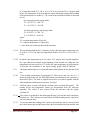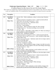
1
AMENDMENT No. 4 TO Doc. No.: MoRTH/CMVR/ TAP-115/116: Issue No.: 4 Document on Test Methods, Testing Equipment and Related Procedures for Testing Type Approval and Conformity of Production (COP) of Vehicles for Emission as per CMV Rules 115,116 and 126. 1. Additional Part XVIII : Details of Standards for Tailpipe Emissions from spark ignition engines (Petrol, CNG and LPG) and compression ignition engines (Diesel) vehicles and Test Procedures for Mass Emission Standards (Bharat Stage IV) for Three Wheeled Vehicles MoRTH/CMVR/TAP115/116 ISSUE NO. 4 STANDARDS FOR PETROL / DIESEL ENGINED VEHICLES PART XVIII Part XVIII : Details of Standards for Tailpipe Emissions from spark ignition engines (Petrol, CNG and LPG) and compression ignition engines (Diesel) vehicles and Test Procedures for Mass Emission Standards (Bharat Stage IV) for Three Wheeled Vehicles Chapter Details 1. Overall Requirements 2. Essential Characteristics of the Vehicle and Engine and Information Concerning the Conduct of Tests MoRTH / CMVR / TAP-115/116 (Issue 4) Page 2 Chapter 1 OVERALL REQUIREMENTS 1. Scope 1.1 This Part applies to the tailpipe emission of three wheeled vehicles equipped with spark ignition engines (Petrol, CNG and LPG) and compression ignition engines (Diesel) for Bharat Stage IV for the three wheelers manufactured on and after the 1st April 2016 for new types of vehicle models and from the 1st April, 2017 for existing types of vehicle models. 1.2 Refer Part XIV, Chapter 16 for tailpipe emission of Hybrid Electric Vehicles. 1.3 This Part should be read in conjunction with applicable Gazette Notification GSR 487(E) th dated 12 Jun, 2015 for which the vehicle is subjected to test. 2. Definitions: 2.1. For 3 Wheelers with equipped with spark ignition engines (Petrol, CNG and LPG) and compression ignition engines (Diesel) refere clause 2.0 of Chapter 1 of Part XIII of this document. 2.2. Evaporative emissions means the hydrocarbon vapors lost from the fuel system of a motor vehicle other than those from tailpipe emissions. 2.2.1. Tank breathing losses are hydrocarbon emissions caused by temperature changes in the fuel tank (assuming a ratio of C 1 H 2.33 ). 2.2.2. Hot soak losses are hydrocarbon emissions arising from the fuel system of a stationary vehicle after a period of driving (assuming a ratio of C 1 H 2.20 ). 2.3. Engine crankcase : means the spaces in, or external to, an engine which are connected to the oil sump by internal or external ducts through which gases and vapors can escape. 3. Application for Type Approval 3.1 The application for type approval of a vehicle model with regard to limitation of tail pipe emissions, evaporative emissions, durability of anti pollution devices from the vehicles shall be submitted by the vehicle manufacturer with a description of the engine and vehicle model comprising all the particulars referred to in Chapter 2 of this Part. A vehicle representative of the vehicle model to be type approved shall be submitted to the testing agency responsible for conducting tests referred in para. 5 of this Chapter. MoRTH / CMVR / TAP-115/116 (Issue 4) Page 3 4. Type Approval : If the vehicle submitted for type approval pursuant to these rules, meet the requirements of Para 5 below, approval of that vehicle model shall be granted. The approval of the vehicle model pursuant to this part shall be communicated to the vehicle manufacturer and nodal agency by the testing agency in the form of certificate of compliance to the CMVR, as envisaged in Rule-126 of CMVR. 5. Specification and Tests: 5.1. General: The components liable to affect the tailpipe and evaporative emissions of gaseous pollutants shall be so designed, constructed and assembled to enable the vehicle, in normal use, despite the vibrations to which they may be subjected to comply with the provisions of this rule. 5.2. Specifications concerning the emissions of pollutants 5.2.1. The vehicle shall be subjected to tests of Type I, II, III, IV, & V as specified below according to the category it belongs. 5.2.2. Type I Test: (Verifying the average tailpipe emissions) 5.2.2.1. Refer clause 5.2.2 of Part XIII of this document for 3 Wheelers equipt with spark ignition (Petrol/ CNG / LPG) and compression ignition engines (Diesel). 5.2.2.2. Type I test emission limit values for 3 wheeler shall be as per GSR 487(E) dated th 12 Jun., 2015 5.2.3. Type II Test (Test for carbon monoxide and Hydrocarbons emissions at idling speed). 5.2.3.1 Refer Clause 5.2.3 Part XIII of this document for below category of Three wheelers:- 5.2.3.1. The idling emission standards for carbon monoxide and Hydrocarbons for spark ignition CNG, LPG vehicles shall be as per notification no. G.S.R.277(E) dated Dated 11th April, 2014. The free acceleration smoke for diesel vehicle shall not exceed as per the limits mentioned in 4.1 of Part I of MoRTH/CMVR/TAP-115-116, Issue 4. MoRTH / CMVR / TAP-115/116 (Issue 4) Page 4 5.2.4. Type III test (Control of crankcase emission gases) : The crank case breather shall be connected to the Intake system in the case of spark ignition four stroke engines, so that there is no escape of crank case gases into atmosphere. This requirement is not applicable for two stroke engines as crank case gases are not vented to atmosphere. This requirement is also not applicable for compression ignition Three wheelers. 5.2.5. Type IV test (determination of evaporative emission). 5.2.5.1. This test shall be carried out on all 3 wheeler petrol vehicles. This procedure is not applicable to Bi fuel Three wheelers (Limp home mode) (i.e. LPG/CNG and Petrol), where the petrol tank capacity does not exceed Three litres 5.2.5.2. When tested in accordance with Chapter 2, evaporative emission shall be less than 2 g/test or 6 g/test, depending upon the option chosen by manufacturer as per applicable BSIV notification. 5.2.6. Type V test (durability of anti-pollution devices): 5.2.6.1 The requirement of durability must be complied on all 3 Wheeler vehicles. This may be established by using the deterioration factor notified in CMVR or by carrying out the durability test. The test represents an ageing test of 30000 km for 3 wheelers, driven in accordance with the program described in Part XIII, chapter 10 of this document on a test track, on the road or on a chassis dynamometer. 5.2.6.1.1 At the request of the manufacturer, the testing agency may carry out the Type I test before Type V test has been completed using the deterioration factors given in Notification. On completion of Type V test, the testing agency may then amend the type-approval results recorded in the Notification with those measured in type V test. 5.2.6.1.2 Deterioration factor are determined using either procedure in Part XIII, chapter 10 of this document or using the values in the notifications at the option of manufacturer. The factors are used to establish compliance with the requirements of 5.2.2.5 and 5.2.4.3 of Part XIII, Chapter 1 of this document. 6. Modifications of the vehicle Model 6.1 Every modification in the essential characteristics of the vehicle model shall be intimated by the vehicle manufacturer to the test agency which type approved the vehicle model. The test agency may either consider that the vehicle with the modifications made may still comply with the requirement, or require a further test to ensure further compliance. MoRTH / CMVR / TAP-115/116 (Issue 4) Page 5 6.2 In case of 6.1 above, the testing agency shall extend the type approval covering the modified specification or the vehicle model shall be subjected to necessary tests. In case, the vehicle complies with the requirements, the test agency shall extend the type approval. 6.3 Any changes to the procedure of PDI and running in concerning emission shall also be intimated to the test agency by the vehicle manufacturer, whenever such changes are carried out. 7 Model Changes (Type I & Type II test) : 7.1 Vehicle models of Different Reference Weights and coast down coefficients : Approval of a vehicle model may under the following conditions be extended to vehicle models which differ from the type approved only in respect of their reference weight. 7.1.1 Approval may be extended to vehicle model of a reference weight requiring merely the use of the next one higher or any lower equivalent inertia, for 3 wheelers. 7.1.2 If the reference weight of the vehicle model for which extension of the type approval is requested requires the use of a flywheel of equivalent inertia lower than that used for the vehicle model already approved, extension of the type approval shall be granted if the masses of the pollutants obtained from the vehicle already approved are within the limits prescribed for the vehicle for which extension of the approval is requested. 7.1.3 If different body configurations are used with the same power plant and drive line and the change in the load equation due to changes in the coefficient of resistances that is within the limits that would be caused by the change of inertia as permitted by Clause 7.1.1 above the approval may be extended. 7.2 Vehicle models with Different Overall Gear Ratios : 7.2.1 Approval granted to a vehicle model may under the following conditions be extended to vehicle models differing from the type approved only in respect of their overall transmission ratios; 7.2.1.1 For each of the transmission ratios used in the Type I Test, it shall be necessary to determine the proportion E = (V 2 - V 1 )/V 1 , where V 1 and V 2 are respectively the speed at 1000 rev/min of the engine of the vehicle model type approved and the speed of the vehicle model for which extension of the approval is requested. MoRTH / CMVR / TAP-115/116 (Issue 4) Page 6 7.2.2 If for each gear ratio E ≤ 8%, the extension shall be granted without repeating the Type I Tests. 7.2.3 If for at least one gear ratio, E > 8% and if for each gear ratio E ≤ 13% the Type I test must be repeated, but may be performed in laboratory chosen by the manufacturer subject to the approval of the test agency granting type approval. The report of the tests shall be submitted to the test agency by the manufacturer. 7.3 Vehicle models of Different Reference Weights, coefficient of coast down and Different Overall Transmission Ratios 7.3.1 Approval granted to a vehicle model may be extended to vehicle models differing from the approved type only in respect of their reference weight, coefficient of coast down and their overall transmission ratios, provided that all the conditions prescribed in Para 7.1 and 7.2 above are fulfilled. 7.4 Note: When a vehicle type has been approved in accordance with the provisions of Para 7.1 to 7.3 above, such approval may not be extended to other vehicle types. 7.5 Vehicle model with different makes of emission related components : 7.5.1 The names of suppliers of items such as ignition coil, magneto, CB point, air filter, silencer, spark plug, catalytic converter etc. mentioned above, the manufacturers shall inform the test agency that In addition to carried out the type approval, the names of new alternate suppliers for these items as and when they are being introduced. 7.5.2 At the time of first type approval or for a subsequent addition of a make for a particular part, work out the combinations of tests in such a way that each make of such parts are tested at least once. 7.6 Crank Case Emission (type III test) & Evaporative Emissions (type IV test) 7.6.1 Approval granted to a vehicle type equipped with a control system for evaporative emissions may be extended under the following conditions. MoRTH / CMVR / TAP-115/116 (Issue 4) Page 7 Test types III and IV (‘X’ in Table 1 means ‘applicable’) Category; 1.2. Subcategory; # 2.1. X X Classification criteria description System propulsion (not) equipped with crankcase ventilation system; X 2.1.1. crankcase ventilation system type; X 2.1.2. operation principle of crank case ventilation system (breather / vacuum / overpress ure); X 2.2. Test type IV 1.1. 2. X Vehicle Test type III 1. Classification criteria description Test type IV Sr . N Test type III Table: 1 propulsion (not) equipped with evaporative emission control system; X 2.2.1. evaporative emission control system type; X 2.2.2. operation principle of evaporative emission control system (active / passive / mech anically or electronically controlled); X 2.2.3. identical basic principle of fuel/air metering (e.g. carburettor / single point injection / multi point injection / engine speed density through MAP/ mass airflow); X 2.2.4. identical material of the fuel tank and liquid fuel hoses is identical; X 2.2.5. the fuel storage volume is within a range of +/– 50 %; X 2.2. the setting of the fuel storage relief valve is identical; X 2.2.6. identical method of storage of the fuel vapour (i.e. trap form and volume, storage medium, air cleaner (if used for evaporative emission control) etc.); X 2.2.7. identical method of purging of the stored vapour (e.g. air flow, purge volume over the driving cycle); X 2.2.8. identical method of sealing and venting of the fuel metering system; X “X” - Applicable Criteria MoRTH / CMVR / TAP-115/116 (Issue 4) Page 8 7.7 Durability of anti-pollution devices (Type V test) 7.7.1 Approval granted to a vehicle type may be extended to different vehicle types, provided that the engine/pollution control system combination is identical to that of the vehicle already approved. To this end, those vehicle types whose parameters described below are identical or remain within the limit values prescribed are considered to belong to the same engine/pollution control system combination. 7.7.1.1 Engine: - 7.7.1.2 number of cylinders, engine capacity (± 15%) configuration of the cylinder block, number of valves, fuel system type of cooling system combustion process cylinder bore center to center dimensions Pollution control system : - Catalytic Converters: o o o o o o o o o - Number of catalytic converters and elements Size and shape of catalytic converters (volume of monolith ± 10%), Type of catalytic activity (oxidizing, three-way) Precious metal load (identical or higher), Precious metal ratio (+/-15%) Substrate (structure and material), Cell density, Type of casing for the catalytic converter(s), Location of catalytic converters (position and dimension in the exhaust system that does not produce a temperature variation of more than 50 K at the inlet of the catalytic converter). This temperature variation shall be checked under stabilized conditions at a speed 42 km/h for 3 wheelers and the load setting of type I test. Air injection : o With or without o Type (pulsair, air pumps....) - EGR: MoRTH / CMVR / TAP-115/116 (Issue 4) Page 9 o With or without 7.7.1.3 Inertia category: The two inertia categories immediately above and any inertia category below. 7.7.1.4 The durability test may be achieved by using a vehicle, the body style, gear box (automatic or manual) and size of the wheels or tyres of which are different from those of the vehicle type for which the type approval is sought. 8 Conformity of Production: As prescribed in Clause 8.0 of Part XIII, Chapter 1 of this document for Type I & Type II test. For Type IV shall be as per para 7, Annexure 1, Chapter2 of this part. MoRTH / CMVR / TAP-115/116 (Issue 4) Page 10 Chapter 2 DETAILS FOR STANDARDS FOR EVAPORATIVE EMISSION FROM 3 WHEELERS FITTED WITH SPARK-IGNITION ENGINES Annexure 1: TYPE-IV TEST: THE DETERMINATION OF EVAPORATIVE EMISSIONS FROM 3 WHEELERS WITH SPARK-IGNITION ENGINES Annexure 2: CALIBRATION OF EQUIPMENT FOR EVAPORATIVE EMISSION TESTING. MoRTH / CMVR / TAP-115/116 (Issue 4) Page 11 ANNEXURE 1 1 INTRODUCTION: This procedure describes a method for the determination of the loss of hydrocarbons by evaporation from the fuel systems of vehicles as described in para 5.2.5.1 of Chapter 1 of this part. While preparing this standard considerable assistance has been taken from: a) b) CALIFORNIA EVAPORATIVE EMISSION STANDARDS AND TEST PROCEDURES FOR 2001 AND SUBSEQUENT MODEL MOTOR VEHICLES 91/441/EEC Air pollution by emission from motor vehicles. 2 DESCRIPTION OF TEST: The evaporative emission Sealed Housing Evaporative Determination (SHED) test (Figure 1) consists of a conditioning phase and a test phase, as follows: a) b) Conditioning Phase: • Driving Cycle as per Indian Driving Cycle (IDC); • Vehicle Soak; Test Phase: • Diurnal (breathing loss) test; • Driving Cycle as per Indian Driving Cycle (IDC); • Hot Soak loss test. Mass emissions of hydrocarbons from the tank breathing loss and the hot soak loss phases are added together to provide an overall result for the test. 3 TEST VEHICLE AND TEST FUEL : 3.1 Test Vehicle 3.1.1 The vehicle shall be in good mechanical condition and before the evaporative test, have been run in and driven at least 1000 km. The evaporative emission control system must be connected and functioning correctly over this period and the carbon canister and evaporative emission control valve subjected to normal use, neither undergoing abnormal purging nor abnormal loading. 3.2 Test Fuel 3.2.1 The reference fuel as applicable for BSIV norms shall be used. If the engine is lubricated by a fuel oil mixture, the oil added to reference fuel shall comply as to grade and quantity with the manufacturer’s recommendation during driving cycle. MoRTH / CMVR / TAP-115/116 (Issue 4) Page 12 4 TEST EQUIPMENT 4.1 Chassis dynamometer The chassis dynamometer must meet the requirements of para 4 of Chapter 3 of Part-XIII, of this document 4.2 Evaporative emission measurement enclosure. Evaporative emission measurement enclosure (SHED). The evaporative emission measurement enclosure shall be a gas-tight rectangular measuring chamber able to contain the vehicle under test. The vehicle shall be accessible from all sides when inside and the enclosure when sealed must be gas tight in accordance with Annexure 2. The inner surface of the enclosure must be impermeable to hydrocarbons. At least one of the surfaces shall incorporate a flexible impermeable material or other device to allow the equilibration of pressure changes resulting from small changes in temperature. Wall design shall be such as to promote good dissipation of heat. 4.3 Analytical System 4.3.1 Hydrocarbon analyser 4.3.1.1 The atmosphere within the chamber is monitored using a hydrocarbon detector of the flame ionisation detector (FID) type. Sample gas must be drawn from the midpoint of one sidewall or roof of the chamber and any bypass flow must be returned to the enclosure, preferably to a point immediately downstream of the mixing fan. 4.3.1.2 The hydrocarbon analyser must have a response time to 90% of final reading of less than 1.5 seconds. Its stability shall be better than 2% of full scale at zero and at 80 ± 20% of full scale over a 15-minute period for all operational ranges. 4.3.1.3 The repeatability of the analyser expressed as one standard deviation shall be better than 1% of full-scale deflection at zero and at 80 ± 20% of full scale on all ranges used. 4.3.1.4 The operational ranges of the analyser must be chosen to give best resolution over the measurement, calibration and leak checking procedures. 4.3.2 Hydrocarbon analyser data recording system: 4.3.2.1 The hydrocarbon analyser must be fitted with a device to record electrical signal output either by strip chart recorder or other data-processing system at a frequency of at least once per minute. The recording system must have operating characteristics at least equivalent to the signal being recorded and must provide a permanent record of results. The record shall show a positive indication of the beginning and end of the fuel tank heating and hot soak periods together with the time elapsed between start and completion of each test. MoRTH / CMVR / TAP-115/116 (Issue 4) Page 13 4.4 FUEL TANK HEATING SYSTEM 4.4.1 The tank fuel heating system shall consist of two separate heat sources with two temperature controllers. A typical heat source is a pair of heating strips. Other sources may be used as required by the circumstances. At the request of manufacturer the test agency may allow manufacturer’s to provide the heating apparatus for compliance testing. The temperature controllers may be manual, such as variable transformers, or they may be automated. Since vapor and fuel temperature are to be controlled separately, an automatic controller is recommended for both the fuel and vapour. The heating system shall not cause hot spots on the wetted surface of the tank, which could cause local over heating of the fuel. Heating strip for the fuel, if used, should be located as low as practicable on the Fuel tank and shall cover at least 10% of the wetted surface. The centerline of the fuel heating strip, if used, shall be below 30% of the fuel depth as measured from the bottom of the fuel tank and approximately parallel to the fuel level in the tank. The centerline of the vapor heating strips, if used, should be located at the approximate height of the center of vapor volume. The temperature controller must be capable of controlling the fuel and vapor temperatures to the heating function described in 5.3.8. Note - In order to ensure uniform and appropriate heating and measurement of temperature for fuel and vapour the following precaution or the manufacturer recommendations shall be followed, such as : (a) No fuel heating pad shall be located above a 40% volume fill line from bottom. Likewise no vapour heating pad in an exposed tank evaporative test should be below the 60% volume fill line from bottom. (b)Separate heating pads for fuel and vapour shall cover as much area as possible respectively. (c)The pasting of heating pads on either side of fuel tank shall be symmetric for fuel and vapour heating. (d)The position of fuel and vapour temperature sensors shall be as close to the area covered by heating pads respectively 4.4.2 With temperature sensors positioned as in paragraph 4.5.2, the fuel heating device shall make it possible to evenly heat the fuel and vapor in the tank in accordance with heating function described in 5.3.8. The heating system shall be capable of controlling the fuel & vapor temperature to ± 1.7 °K of the required temperature during the tank heating process. 4.4.3 Not withstanding the requirements of 4.4.2. if a manufacturer is unable to meet the heating requirement specified, for example due to use of thick-walled plastic fuel tanks, then the closest possible alternative heat slope shall be used. Prior to the commencement of any test, manufacturers shall submit engineering data to the testing agency to support the use of an alternative heat slope. MoRTH / CMVR / TAP-115/116 (Issue 4) Page 14 4.5 TEMPERATURE RECORDING 4.5.1 The temperature in the chamber is recorded at two points by temperature sensors, which are connected so as to show a mean value. The measuring points are extended approximately 0.1m into the enclosure from the vertical centerline of each sidewall at a height of 0.9 ± 0.2m. 4.5.2 The temperatures of the fuel and fuel vapor shall be recorded by means of the sensor positioned in the fuel tank as in section 5.1.1. When sensors cannot be positioned as specified in paragraph 5.1.1, such as where a fuel tank with two ostensibly separate chambers is used, sensors shall be located at the approximate mid-volume of each fuel or vapor containing chamber. In this case, the average of these temperature readings shall constitute the fuel and vapor temperatures. 4.5.3 Throughout the evaporative emission measurements, temperature shall be recorded or entered in to a data processing system at a frequency of at least once per minute.. 4.5.4 The accuracy of the temperature recording system shall be within ± 1.7 K and the temperature must be capable of being resolved to 0.5 K. The recording or data processing system must be capable of resolving time to ± 15 seconds. 4.5.5 4.6 Fan 4.6.1 It must be possible to reduce the hydrocarbon concentration in the chamber to the ambient hydrocarbon level by using one or more fans or blowers with the SHED door(s) open. 4.6.2 The chamber must have one or more fans or blowers of likely capacity 0.1 to 0.5 m3 /s with which to thoroughly mix the atmosphere in the enclosure. It must be possible to attain an even temperature and hydrocarbon concentration in the chamber during measurements. The vehicle in the enclosure must not be subjected to a direct stream of air from the fans or blowers. 4.7 Gases 4.7.1 The following pure gases must be available for calibration and operation: a) Purified synthetic air (purity: < 1 ppm C1 equivalent < 1 ppm CO, < 400 ppm CO2, 0.1 ppm NO); oxygen content between 18 and 21% by volume; b) Hydrocarbon analyzer fuel gas (40 ± 2% hydrogen, and balance helium with less than 1 ppm C1 equivalent hydrocarbon, less than 400 ppm CO2); c) Propane (C3 H8), 99.5% minimum purity. MoRTH / CMVR / TAP-115/116 (Issue 4) Page 15 4.7.2 Calibration and span gases shall be available containing mixtures of propane (C3 H8) and purified synthetic air. The true concentrations of a calibration gas must be within ± 2% of the stated figures. The accuracy of the diluted gases obtained when using a gas divider must be to within ± 2% of the true value. The concentrations specified in MOSRTH/CMVR/TAP-115/116, Issue 4 as amended time to time, may also be obtained by the use of a gas divider using synthetic air as the diluent gas. 4.8 Additional equipment 4.8.1 The relative humidity in the test area must be measurable to within ± 5% 4.8.2 The pressure within the test area must measurable to within ± 0.1 kPa. 4.9 Alternative Equipment 4.9.1 At the request of the manufacturer, the testing agency may authorize the use of alternative equipment provided that it can be demonstrated that such equipment gives equivalent results. 5 TEST PROCEDURE 5.1 Test preparation 5.1.1 The vehicle is mechanically prepared before the test as follows: a) The exhaust system of the vehicle shall not exhibit any leaks; b) The vehicle may be steam - cleaned before the test; c) The fuel tank of the vehicle shall be equipped with temperature sensors so that the temperature of the fuel and fuel vapour in the fuel tank can be measured when it is filled to 50% ± 2% of its Manufacturer declared capacity. Sensors should be positioned as described in 4.5.2; d) Additional fittings, adaptors or devices may optionally be fitted to allow a complete draining of the fuel tank. Alternatively, the fuel tank may be evacuated by means of a pump or siphon that prevents fuel spillage. 5.2 Conditioning Phase 5.2.1 The vehicle shall be taken into the test area where the ambient temperature is between 293.2 K and 303.2 K (20°C and 30°C). 5.2.2 The fuel tank(s) shall be drained through the provided fuel tank(s) drain(s) and charged with the specified test fuel to half of the tank capacity. . 5.2.3 The vehicle is placed on a chassis dynamometer and is driven through the driving test cycle specified as per the Indian Driving Cycle (IDC). Exhaust emissions may MoRTH / CMVR / TAP-115/116 (Issue 4) Page 16 be sampled during this operation but the results are not used [for the purpose of exhaust emission type approval]. 5.2.4 The vehicle is parked in the test area for the minimum period 6- 36 hrs. 5.3 TANK BREATHING (DIURNAL) EVAPORATIVE EMISSION TESTS 5.3.1 The measuring chamber shall be vented / purged for several minutes immediately before the test until a stable background is obtainable. The chamber mixing fan (s) must be switched on at this time also. 5.3.2 The hydrocarbon analyser must be zeroed and spanned immediately before the test 5.3.3 The fuel tank(s) shall be emptied as described in paragraph 5.1.1 and refilled with test fuel at a temperature of between 283.2K and 287.2 K (10°C and 14°C) to 50 ± 2% of its Manufacturer declared capacity. and with the motorcycle resting on its center stand (or a similar support) in the vertical position. The fuel cap (s) of the vehicle must not be fitted at this point. 5.3.4 In the case of vehicles fitted with more than one fuel tank, all the tanks shall be heated in the same way, as described below. The temperatures of the tanks must be identical to within ± 1.5 °K. 5.3.5 The test vehicle shall be brought into the test enclosure with the engine switched off, parked in an upright position and fuel tank shut of valve if manual, shall be put in off position as instructed in user’s manual. The fuel tank sensors and the fuel tank heating device, if necessary, shall be connected. Immediately begin recording the fuel temperature and the air temperature within the enclosure. If a venting/purging fan is still operating, it shall be switched off at this time. 5.3.6 The fuel and vapor may be artificially heated to the starting temperature of 288.7 K (15.5°C) ± 1 K and 294.2 K (21.0°C) ± 1 K respectively. 5.3.7 As soon as the fuel temperature reaches 287.2 K (14.0 °C) and the vapour temperature reaches 292.7 K (19.5 °C), the cap of the fuel tank(s) shall be sealed and the chamber shall be sealed so that it is gas-tight. 5.3.8 As soon as the fuel reaches a temperature of 288.7K (15.5°C) ± 1 K and the vapour temperature 294.2 K (21°C) 2 the test procedure shall continue as follows : a) The hydrocarbon concentration, barometric pressure and the temperature shall be measured to give the initial readings CHCi, i, Pi and Ti for the tank heat build test; MoRTH / CMVR / TAP-115/116 (Issue 4) Page 17 b) A linear heat build of 13.3 K or 20 ± 0.5 K over a period of 60 ± 2 minutes shall begin. The temperature of the fuel and fuel vapour during the heating shall conform to the function below to within ± 1.7 K, or the closest possible function as described in 4.4.3. For exposed type fuel storage tanks: Tf = (0.3333)* t + 288.7 K Tv = (0.3333)* t + 294.2 K For non-exposed type fuel storage tanks: Tf = (0.2222) * t + 288. 7 K Tv = (0.2222) *t + 294.2 K where: Tf = required temperature of fuel (K); Tv = required temperature of vapour (K); t = time from start of the tank heat build in minutes. 5.3.8.1 The test duration shall be 60 ± 2 minutes, giving a fuel and vapour temperature rise of 20 K or 13.3 K. The final fuel temperature shall be 308.5 K ± 0.5 K or 301.3 ± 0.5 K. 5.3.8.2 An initial vapor temperature up to 5°C above 21°C may be used. For this condition, the vapor shall not be heated at the beginning of the diurnal test. When the fuel temperature has been raised to 5.5°C below the vapor temperature by following the Tf function, the remainder of the vapor heating profile shall be followed. 5.3.9 The hydrocarbon analyser is zeroed and spanned immediately before the end of the test. 5.3.10 If the heating requirements in paragraph 5.3.8 have been met over the 60 ± 2 minute period of the test, the final hydrocarbon concentration in the enclosure is measured (CHCf). The time or elapsed time of this is recorded, together with the final temperature and barometric pressure Tf and pf. 5.3.11 The heat source is turned off and the enclosure door unsealed and opened. The heating device and temperature sensor are disconnected from the enclosure apparatus. The vehicle is now removed from the enclosure with the engine switched off. 5.3.12 The vehicle is prepared for the subsequent driving cycle and hot soak evaporative emission test. The cold start test must follow the tank breathing test by a period of not more than one hour. To prevent abnormal loading of the canister, fuel tank caps may be removed from the vehicle during the period between the end of the diurnal test phase and the start 5.3.13 MoRTH / CMVR / TAP-115/116 (Issue 4) Page 18 of the driving cycle. The driving cycle shall begin within 60 minutes of the completion of the breathing loss test. 5.4 Driving Cycle: 5.4.1 Following the tank breathing losses test, the vehicle is pushed or otherwise maneuvered onto the chassis dynamometer with the engine switched off. It is then driven through the Indian driving cycle (IDC). At the request of the manufacturer, exhaust emissions may be sampled during this operation, but the results are not used [for the purpose of exhaust emission type – approval]. 5.5 HOT SOAK EVAPORATIVE EMISSIONS TEST: 5.5.1 The determination for evaporative emissions is concluded with the measurement of hydrocarbon emissions over a 60-minute hot soak period. The hot soak test shall begin within seven minutes of the completion of the driving cycle specified in paragraph 5.4.1 Before the completion of the driving cycle run, the measuring chamber must be purged for several minutes until a stable hydrocarbon background is obtained. The enclosure mixing fan(s) must also be turned on at this time.. 5.5.2 The hydrocarbon analyser must be zeroed and spanned immediately prior to the test. 5.5.3 The vehicle shall be pushed or otherwise moved into the measuring chamber with the engine switched off and fuel tank shut of valve if manual be put in off position. 5.5.4 The enclosure doors are closed and sealed gas-tight within seven minutes of the end of the driving cycle. 5.5.5 The start of a 60 ± 0.5 minute hot soak period begins when the chamber is sealed. The hydrocarbon concentration, temperature and barometric pressure are measured to give the initial readings CHCi , Pi and Ti for the hot soak test. These figures are used in the evaporative emission calculation, clause 6. The ambient SHED temperature T must not be less than 293.2 K and not more than 303.2 K during the 60 minute hot soak period. The hydrocarbon analyser must be zeroed and spanned immediately before the end of the 60 ± 0.5 minute test period. 5.5.7 At the end of the 60 ± 0.5 minute test period measure the hydrocarbon concentration in the chamber. The temperature and the barometric pressure are also measured. These are the final readings C HCf , P f and T f for the hot soak test used for the calculation in clause 6. This completes the evaporative emission test procedure. MoRTH / CMVR / TAP-115/116 (Issue 4) Page 19 5.6 Alternative test procedures : 5.6.1 At the request of the manufacturer alternative methods may be used to demonstrate compliance with the requirements of this annex. In such cases, the manufacturer shall satisfy the test agency that the results from the alternative test can be correlated with those resulting from the procedure described in this annex. This correlation shall be documented and included in the test report. 6 CALCULATION OF RESULTS : 6.1 The evaporative emission tests described in clause 5 allow the hydrocarbon emissions from the tank breathing and hot soak phases to be calculated. Evaporative losses from each of these phases are calculated using the initial and final hydrocarbon concentrations, temperatures and pressures in the enclosure, together with the net enclosure volume. The formula below is used: M HC = k * V * 10 -4 [C HCf * P f / T f - C HCi * P i / T i ] Where: M HC = mass of hydrocarbon emitted over the test phase (grams). C HC = measured hydrocarbon concentration in the enclosure (ppm (volume) C equivalent). V = net enclosure volume in cubic meters corrected for the volume of the vehicle, If the volume of the vehicle is not determined a volume of 0.25 m3 is subtracted. T = ambient chamber temperature, K. P = barometric pressure in kPa H/C = hydrogen to carbon ratio. k = 1.2 (12 + H/C): Where: i f H/C H/C 6.2 is the initial reading. is the final reading. is taken to be 2.33 for tank breathing losses. is taken to be 2.20 for hot soak losses. Overall results of test The overall hydrocarbon mass emission for the vehicle is taken to be: M total = M TH + M HS M total = overall evaporative mass emissions of the vehicle (grams). M TH = Evaporative hydrocarbon mass emission for the tank heat build (grams). M HS = Evaporative hydrocarbon mass emission for the hot soak (grams). MoRTH / CMVR / TAP-115/116 (Issue 4) Page 20 FIGURE 1. EVAPORATIVE EMISSION DETERMINATION SHED TEST Steam clean of vehicle (if necessary) Vehicle Preconditioning With IDC 5 minutes Maximum Soak period as per Table 1 Fuel Drain Fuel Tank Fill Diurnal test in 1 hour Ambient temperature 293.2-303.2 K (20-30 °C) 50% ± 2% of nominal tank capacity .Fuel temperature 283.2 to 287.2 K(10-14°C) Temperature as per cclause no. 5.3.8 1 hour maximum Dynamometer test as per IDC 7 minutes maximum Hot soak in chamber 1 hour . End Starting temperature inside shed is a Minimum of 293.2 K(20°C) Maximum 303.2 K (30°C) Test results(grams) = diumal results (grams)+ hot soak result (grams) Note: 1. Tailpipe emissions may be measured during dynamometer test ,but these are not used for certification MoRTH / CMVR / TAP-115/116 (Issue 4) Page 21 7.0 CONFORMITY OF PRODUCTION ( for vehicles with Evaporative control system) 7.1 For routine end of production-line testing, the holder of the approval may demonstrate compliance by sampling vehicles which shall meet the following requirements. Alternatively, the full test procedure described in this Annex shall be carried out. At the request of the manufacturer an alternative test procedure may be used, if the procedure has been presented to and has been accepted during the type approval procedure by the test agency. 7.2 Test for leakage: 7.2.1 Vents to the atmosphere from the evaporative emission control system shall be isolated. 7.2.2 A pressure of 370 ± 10 mm of H2O shall be applied to the fuel system. 7.2.3 The pressure must be allowed to stabilize prior to isolating the fuel system from the pressure source. 7.2.4 Following isolation of the fuel system, the pressure shall not drop by more than 50 mm of H2O in five minutes. 7.3 Tests for Venting: 7.3.1 Vents to the atmosphere from the emission control shall be isolated. 7.3.2 A pressure of 370 ± 10 mm of H2O shall be applied to the fuel system. 7.3.3 7.3.4 The pressure shall be allowed to stabilize prior to isolating the fuel system from the present source. The venting outlets from the emission control systems to the atmosphere shall be reinstated to the production condition. 7.3.5 The pressure of the fuel system shall drop to below 100 mm of H2O within two minutes. 7.4 Purge Test: 7.4.1 Equipment capable of detecting an airflow rate of 0.25 litres in one minutes shall be attached to the purge inlet and a pressure vessel of sufficient size to have negligible effect on the purge system shall be connected via a switching valve to the purge inlet, or alternatively. 7.4.2 The manufacturer may use a flow meter of his own choice, if acceptable to the competent authority. 7.4.3 The vehicle shall be operated in such a manner that any design features of the purge system that could restrict purge operation is detected and the circumstances noted. MoRTH / CMVR / TAP-115/116 (Issue 4) Page 22 7.4.4 Whilst the engine is operating within the bounds note in 8.4.3 the air flow shall be determined by either. 7.4.4.1 The device being switched in a pressure drop from atmosphere to a level indicating that a volume of 0.25 litres of air has flowed into the evaporative emission control system within one minute or 7.4.4.2 An alternative flow measuring device with a detectable reading of no less than 0.25 litre per minute. 7.5 If the requirements of 7 .2, 7 .3 and 7 .4 are not met the competent authority must ensure that all necessary steps are taken to re-establish conformity of production as rapidly as possible by conducting a test as per Part-VII, Chapter-II. MoRTH / CMVR / TAP-115/116 (Issue 4) Page 23 Annexure 2 1 CALIBRATION FREQUENCY AND METHODS 1.1 All equipment must be calibrated before its initial use and then calibrated as often as necessary and in any case in the month before type-approval testing. The calibration methods to be used are described in this Annexure. 2 CALIBRATION OF THE ENCLOSURE: 2.1 Initial determination of enclosure internal volume 2.1.1 Before its initial use, the internal volume of the chamber must be determined as follows. The internal dimensions of the chamber are carefully measured, allowing for any irregularities such as bracing struts. The internal volume of the chamber is determined from these measurements. 2.1.2 The net internal volume is determined by subtracting 0.25 m3 from the internal volume of the chamber. Alternatively the actual volume of the vehicle of the test vehicle may be subtracted. 2.1.3 The chamber shall be checked as in item 2.3. If the propane mass does not tally to within ± 2% with the injected mass, then corrective action is required. 2.2 Determination of chamber background emissions This operation determines that the chamber does not contain any materials that emit significant amounts of hydrocarbons. The check must be carried out at the enclosure's introduction to service, after any operation in the enclosure which may affect background emissions and at a frequency of at least once per year. 2.2.1 Calibrate the analyser (if required), The Hydrocarbon analyser shall be zeroed and spanned immediately, before the test. 2.2.2 Purge the enclosure until a stable hydrocarbon reading is obtained. The mixing fan is turned on if not already on. The hydrocarbon analyzer must be zeroed and spanned immediately before the end of the test 2.2.3 Seal the chamber and measure the background hydrocarbon concentration, temperature and barometric pressure. These are the initial readings C HCi , Pi and Ti used in the enclosure background calculation. 2.2.4 The enclosure is allowed to stand undisturbed with the mixing fan on for a period of four hours. 2.2.5 At the end of this time use the same analyser to measure the hydrocarbon concentration in the chamber. The temperature and the barometric pressure are MoRTH / CMVR / TAP-115/116 (Issue 4) Page 24 also measured. These are the final readings C HCf , P f and T f . The hydrocarbon analyzer must be zeroed and spanned immediately before the end of the test. 2.2.6 Calculate the change in mass of hydrocarbons in the enclosure over the time of the test according to section 2.4 the background emission of the enclosure must not exceed 0.4 g. 2.3 Calibration and hydrocarbon retention test of the chamber: The calibration and hydrocarbon retention test in the chamber provides a check on the calculated volume in 2.1 and also measures any leak rate. 2.3.1 Purge the enclosure until a stable hydrocarbon concentration is reached. Turn on the mixing fan, if not already switched on. The hydrocarbon analyser is zeroed, calibration if required, and spanned. 2.3.2 Seal the enclosure and measure the background concentration, temperature and barometric pressure. These are the initial readings C Hci , P I and T I used in the enclosure calibration. 2.3.3 Inject a quantity of approximately 4 grams of propane into the enclosure. The mass of propane must be measured to an accuracy and precision of ±2.0% of the measured value. 2.3.4 Allow the contents of the chamber to mix for five minutes. The hydrocarbon analyzer must be zeroed and spanned immediately before the following test and then measure the hydrocarbon concentration, temperature and barometric pressure. These are the final readings C HCf , P f and T f for the calibration of the enclosure. 2.3.5 Using the readings taken in 2.3.2 and 2.3.4 and the formula in 2.4, calculate the mass of propane in the enclosure. This must be within ± 2% of the mass of propane measured in 2.3.3. Allow the contents of the chamber to mix for a minimum of four hours. At the end of this period measure and record the final hydrocarbon concentration, temperature and barometric pressure. The hydrocarbon analyzer must be zeroed and spanned immediately before the end of the test. 2.3.6 2.3.7 Calculate using the formula in 2.4, the hydrocarbon mass from the readings taken in 2.3.6 and 2.3.2. The mass may not differ by more than 4% from the hydrocarbon mass given by 2.3.5. MoRTH / CMVR / TAP-115/116 (Issue 4) Page 25 2.4 Calculation The calculation of net hydrocarbon mass change within the enclosure is used to determine the chamber's hydrocarbon background and leak rate. Initial and final readings of hydrocarbons concentration, temperature and barometric pressure are used in the following formula to calculate the mass change. MHC = k * V * 10 -4 [ CHCf * Pf / Tf - CHCi * Pi/ Ti] where: MHC = hydrocarbon mass in grams. CHC = hydrocarbon in the enclosure (ppm Carbon (NB: ppm carbon = ppm propane *3)), V = net enclosure volume in cubic metres. T = ambient temperature in the enclosure, K. P = barometric pressure in kPa. k = 1 7.6: When: i is the initial reading. f is the final reading. 3 CHECKING OF FID HYDROCARBON ANALYSER: 3.1 Detector response optimization: The FID must be adjusted as specified by the instrument manufacturer. Propane in air should be used to optimize the response on the most common operating range. 3.2 Calibration of the HC analyser: The analyser should be calibrated using propane in air and purified synthetic air. See section 4.5.2 of Part XIII, Chapter 3 (Calibration and span gases). Establish a calibration curve as described in sections 4.1 to 4.5 below 3.3 Oxygen interference check and recommended limits: The response factor (R ) for a particular hydrocarbon species f in the ratio of the FID C reading to the gas cylinder concentration, expressed as ppm C . The concentration of the test gas must be at a level to give a response of approximately 80% of full scale deflection, for the operating range. The concentration must be known, to an accuracy of ± 2% in reference to a gravimetric standard expressed in volume. In addition the gas cylinder must be preconditioned for 24 hours at a temperature between 293 K and 303 K (20° and 30°C). Response factors should be MoRTH / CMVR / TAP-115/116 (Issue 4) Page 26 determined when introducing an analyser into service and thereafter at major service intervals. The reference gas to be used is propane with balance purified air which is taken to give a response factor of 1.00. The test gas to be used for oxygen interference and the recommended response factor range are given below: Propane and nitrogen 0.95 ≤ Rf ≤ 1.05. 4 CALIBRATION OF THE HYDROCARBON ANALYSER Each of the normally used operating ranges are calibrated by the following procedure: 4.1 Establish the calibration curve by at least five calibration points spaced at evenly as possible over the operating range. The nominal concentration of the calibration gas with the highest concentration to be at least 80% of the full scale. 4.2 Calculate the calibration curve by the method of least squares. If the resulting polynominal degree is gr e a t e r than 3 then the number of calibration points must be at least the number of the polynominal degree plus 2. 4.3 The calibration curve must not differ by more than 2% from the nominal value of each calibration gas. 4.4 Using the coefficients of the polynominal derived from 4.2, a table of indicated reading against true concentration shall be drawn up in steps of no grater than 1% of full scale. This is to be carried out for each analyser range calibrated. The table shall also contain other relevant data such as: Date of calibration, span and zero potentiometer readings (where applicable) Nominal scale Reference data of each calibration gas used. The actual and indicated value of each calibration gas used together with the percentage differences. FID fuel and type, FID air pressure 4.5 If it can be shown to the satisfaction of the Regulatory Agency that alternative technology (e.g. computer, electronically controlled range switch) can give equivalent accuracy, then those alternatives may be used. F:\DdriveBKP\D Part\TAP\TAP Doc Issue 4 Part XVIII 1-9-2015.doc MoRTH / CMVR / TAP-115/116 (Issue 4) Page 27