1
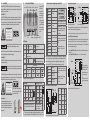
5. Laser Safety 6. The scanCONTROL 2800/2810 sensors operate with a semiconductor laser having a wavelength of 658 nm (visible/red). The laser operation is indicated visually by the LED on the sensor and on the controller. Connections, LED Displays Laser ON/OFF Reset button Power Sensor Mode button Switch-, Synchron- and Trigger Signal, Laser ON/OFF Video output Analog output Laser Class 2M scanCONTROL 2800/2810 sensors with a maximum laser power up to 15 mW are classified in Laser Class 2M (IIM). The following information labels are fitted to the sensor housing (front and rear side). If both information labels are hidden in the installed state, the user must ensure that additional labels are fitted at the point of installation. Laser radiation Do not stare into the beam or view directly with optical instruments Class 2M Laser Product IEC 60825-1:2008-05 Connections to PC P≤15 mW; E≤7.5 mW/cm²; =658 nm Serial interfaces The Laser ON/OFF switch disconnects the power to the laser sensor for maintenance purposes. If the switch is in position „Off“, the associated green LED is off and the sensor connector may be disconnected. Switch, synchron and trigger signal, Laser ON/OFF Lasers of Class 2M are not subject to notification and a laser protection officer is not required. Mark the laser area recognizable and everlasting. „Power on“ „Error“ Laser Class 3B scanCONTROL 2800/2810 sensors with a maximum laser power up to 50 mW are classified in Laser Class 3B (IIIB). Injury to the eye or the skin via laser radiation! Consciously close your eyes or turn away if the laser radiation impinges on the eye or the skin. Class 3B (IIIB) laser sensors are notifiable and a laser protection officer is required either. During operation the laser area has to be restricted and marked. The following information label should be fitted to the sensor housing (front and rear side): Laser radiation Avoid exposure to the beam Class 3B Laser Product IEC 60825-1:2008-05 P≤50 mW; =658 nm Beam attenuator The beam attenuator prevents access to all laser and collateral radiation. The figures show the sensor with closed and open beam attenuator. The beam attenuator must be open during measurement. Sensors need an external key switch to switch off the laser to be classified in Laser Class 3B (IIIB). „Control“ 8 Input + 2 Input Output Output Output - 12 --- Analog output (2 x koaxial) Pin Assignment PC2800-x (old in ( )) Pin Assignment 1 +24 VDC 2 Analog 1 (z) white 3 GND 1 1 2 black View: Solder-pin side, male cable connector The minus pole of the supply voltage (Power GND) is electrically isolated from the system ground. Error, opto decoupled The resistance in the conducting state is 15 Ohm or less at IL = 100 mA. Output Output - 9 Output - Digital output 1, opto decoupled Open collector outputs, short circuit and reverse-polarity protected up to 30 VDC, Digital output 2, opto decoupled The resistance in the conducting state is 15 Ohm or less at IL = 100 mA. Digital output 3, opto decoupled Output Circuit of the Error and Mode Outputs C2800-x 1 4 2 3 Controller screen Solderpin side, 1 GND 2 screen male 50 Ohm output impedance, cable 5 mA output current max., connector not short-circuit-proof 4 Mode 2, opto decoupled Open collector outputs, short circuit and reverse-polarity protected up to 30 VDC, n.c. 14 Output + Power supply (black or blue) Mode 1, opto decoupled Case Synchronization output circuit 7 RL Output Analog 2 (x) brown The sensor may only be plugged/unplugged with power switched off, i.e. with the operating voltage switched off or with the keyswitch in the “Off” position (Laser off). Periphery max. 30 VDC + + 1...10 kOhm T IL max. 100 mA 0 V GND Mode Output Mode1 Output Mode 2 Factory setting T closed T closed 1 T open T closed 2 T closed T open 3 T open T open States on the error output: T is closed, if an error occurs. UF = appr. 1 V Synchronization input circuit The optocoupler at the sync input needs a current of 10 to 15 mA for operation. Do not exceed this current value with external trigger sources. 1) Resistor Rv is used in combination with a trigger input only, see Chap. 6.5 instruction manual. Laser ON/OFF, Mode and Encoder Inputs The two available digital inputs with the same input circuit are configured in the standard version as “laser on/off” and “mode” inputs. They can be directly controlled by open collector transistor inputs or relay contacts. The power supply + 24 V DC is internally connected as an auxiliary power supply. i Laser Class 2M/IIM (15 mW): Laser is on, without connection between the pins 13 and 3 also. Laser Class 3B/IIIB (50 mW): Laser is on, if Pin 13 and 3 are connected. External circuit with load (e.g. relay) between external auxiliary power (e.g. power supply + 24 V DC) and the output+. Connect the negative pole of the auxiliary power with the negative pole of the power supply (does not apply with use of the power supply). 4 brown The connections 2, 3, 4, 5 and 9 are electrically connected to the minus pole (Power-GND) of the 24 V DC supply voltage. Controller I = 10...15 mA 100 Ohm 5 15-pole HD subminiature connector, solder pin side male cable connector Optocoupler Periphery R V1 1 Periphery Sync-out 10 1 Mode, optocoupler 15 Output + Mode 3 A green LED on the sensor signals “laser on”. i Laser On/Off - 10 Output + (red) 6 Optocoupler 3.3 V Controller 33 Ohm 15 Controller Periphery Using the scanCONTROL 2810 sensor the pin assignment changes as follows: Operation mode Mode 1 Mode 2 „Mode 2“ 3 5 white 11 GND Sync. Out System ground 13 Laser On/Off + 9 „Mode 1“ Housing Screen 6 14 Output + Laser is on Function, Remark 11 Sync. Out 4 Errors are encoded by different flashing sequences, see Chap. 13.3 instruction manual No communication flashes long during data transmission with PC flashes short during control access GND Sync. In - 5 Power supply is on Laser is off Default 2 Sync. In + 7 10 Output + No power supply „Laser on“ 1 15 Output + LED Displays Hazard to the eye via laser radiation! Consciously close your eyes or turn away if the laser radiation impinges on the eye. Pin Assignment Synchronization and Triggering HTL 8 (13) 8 (13) 8 (13) I ca. 7 mA 3.3 kOhm 2 (3) 2 (3) Encoder Relay 2 (3) OpenCollector Input circuit of the laser ON/OFF and mode inputs. +24 VDC The mode input reacts like the identically named button and switches cyclically between the various user modes. Pin 8 and pin 2 are the mode or encoder inputs. FireWire Connection (1394), Standard connection to PC Please insert the scanCONTROL Demo CD in the CD-ROM device. Follow the dialog through the installation process. FireWire (or the IEEE 1394 bus) is a serial bus system which can be branched as required with up to 63 devices operating together on one PC interface. The data are transmitted in both directions (bi-directional) on symmetrical and shielded two wire lines via standard cable. A. Reading of installation help Restrictions: ------ B. Installation of software The branching must not include loops. A maximum of 17 devices can be cascaded in a line (“daisy-chained”). The maximum cable length between two devices is 4.5 m. The maximum length of a “daisy chain” section is 72 m. The data rate of 400 Mbit/s applies to the whole bus and must be shared between the connected devices. In the standard configuration up to four scanCONTROL 2800/2810 controllers can be operated on one bus. PC with PCI interface card Controller 1 Matrox Meteor II control mode 1 mode mode 2 1394 sensor laser on error on 1394 i 1394 analog video laser off power on 24VDC on control mode 1 mode 3 RS 232 mode 2 RS 422 synchron 1394 1394 sensor laser on error 1394 analog RS 422 On the left side you can adjust the settings for your measurement task, the right side shows the profile data and information about the measurement. synchron IEEE 1394 IEEE 1394 Camera 1 Example of a FireWire configuration 6-pole connector Signal NC 3 TPB- 4 TPB+ 5 TPA- 6 TPA+ 4 6 Micro-Epsilon recommends to use the SCD-IEEE-1394-3 FireWire cable from the optional accessories. Three fully equivalent 6-pole connection sockets are provided with connection assignment according to the 1394-1995 specification. The controller does not supply any operating voltage to the 1394 connection sockets. The IEEE 1394 (FireWire) interfaces are electrically isolated from the rest of the circuit. View on solder pin side 7. System Requirements scanCONTROL Software -- Windows XP SP 2 (32) / Windows Vista (32) / Windows 7 (32/64) -- Pentium III 800 MHz / 512 MB RAM -- Screen resolution: 1024 x 76 8. i Quick Start: Commissioning, Software Install the software. Sensor and controller need a warm-up time of typically 20 minutes for high precision measurements. Install the drivers for the measuring system according to the instructions on the supplied CD-ROM ([CD]:\\Documentation\english\Installation\index.html). The PIN numbers refer to the scanCONTROL 2800/2810. 1 2 3 NC 5 1 Connector type „1394“ 2 Pin Connect the shield of the power supply cable to the PE protective earth conductor of the main power supply. Close plug-in connections not needed with the supplied protective caps for ODU sockets. Switch on the 24 VDC power supply. 9. Driver Installation for Windows XP Finish the installation of the Configuration Tools software completely. This procedure is described in section 8. Connect the controller to the PC using the 1394 FireWire cable. Switch on the power supply. If the installation doesn’t start automatically, search for scanCONTROL in the device manager (Start > Control Panel > System > Device Manager). scanCONTROL is classified as camera device and is either located under “Imaging Devices” or “Other Devices”. Rightclick the camera device and choose “Update Driver”. 11. How to Access Profile Data 2. Profile data of scanCONTROL can be accessed via: -- DCAM standard v.1.30 for digital cameras via IEEE 1394 FireWire interface -- SDK for fast application integration (C, C++ and others) For details refer to the enclosed online manuals. 12. Further Information Please refer to -- the enclosed online manual -- the section „Status and Error Messages“ and „Notes“ in the scanCONTROL Configuration Tools manual. You will find details to the separate programs in the respective instruction manuals or in the instruction manual of this sensor, Chap. 6.2. You will find the instruction manuals online or on the provided CD. Mark “No, not this time” and click on “Next”. www.micro-epsilon.com MICRO-EPSILON Messtechnik GmbH & Co. KG Königbacher Str. 15 Click on ”Continue anyway” to confirm this dialog. Click on “Finish” to end the driver installation. If you want to install the driver at a later date or in case of an incorrect installation of the driver, you have to install the driver manually. Warnings Connect the power supply and the display-/output device in accordance with the safety regulations for electrical equipment. The power supply may not exceed the specified limits. Read the detailed instruction manual before operation of the sensor. You will find this online or on the provided CD. The ”Hardware Update Wizard” will appear. Click on ”Next” to confirm this dialog. Now the operating system installs the driver for scanCONTROL. The ”Hardware installation” dialog will appear. 1. >> Damage to or destruction of the sensor/controller Connect the controller to the power supply. IEEE 1394 / Controller 3 scanCONTROL 2800/2810 Avoid shock and vibration to the sensor/controller. Avoid continuous exposure to dust and spray on the sensor/controller. Avoid exposure to aggressive materials (washing agent, penetrating liquids or similar) on the sensor. Connect the controller to display or monitoring units. IEEE 1394 Assembly Instructions >> Danger of injury, damage or destruction of the sensor/controller Connect the sensor to the controller. Connect the controller to the PC using a FireWire cable. video 3 RS 232 If the software shows the error message “No scanCONTROL found” in the status line, please check the installed driver in the device manager (Start > Control Panel > System > Device Manager). The sensor may only be connected to the controller with power switched off or with the keyswitch in the “Off” position (Laser off). Mount the sensor according to the installation instructions. reset power on 24VDC First Profile Now start the scanCONTROL Configuration Tools software. Click on “Display Profiles“ in the main window. C. Further informations in the online documentation Controller 2 reset laser off 10. 94496 Ortenburg, Germany, Tel. +49 (0) 85 42/1 68-0 *X9771109-A05* X9771109-A051105HDR Notes on CE Identification -- The following applies to the scanCONTROL 2800/2810: EU directive 2004/108/EC and EU directive 2011/65/EC -- The sensor fulfills the specifications according to the following standards: -- DIN EN 55011/ 11.2007 / Industrial scientific and medical (ISM) equipment / Electromagnetic disturbance characteristics -- DIN EN 61 000-6-2/ 03.2006 / Electromagnetic Compatibility (EMC) / Immunity to interference / industrial area -- DIN EN 61326/ 10.2006 / Electrical equipment The sensor fulfills the specifications of the EMC requirements, if the instructions in the manual are followed. 3. Proper Environment 4. Standard Equipment scanCONTROL 2800/2810 ------- Protection class: IP 65 (with connected sensor cable) Operating temperature:0 to +50 °C (+32 to +122 °F), by free circulation of air Storage temperature: -20 to +70 °C ( -4 to +158 °F) Humidity: 5 - 95 % (non condensing) Vibration: DIN EN 60068-2-6 (sine shaped) Mechanical shock: DIN EN 60068-2-29 -- 1 Sensor LLT2800/2810 and controller -- 1 Power supply cable PC2800-3; round connector and free cable ends -- 1 Analog output plug, 4-pole, (ODU, Series MiniSnap L, Order no. S11L0C - T04MJGO - 7200) -- 1 scanCONTROL Demo-CD with drivers, programs and documentation -- 1 Sensor inspection log / Assembly instructions -- 1 FireWire connecting cable, 3 m long.