1
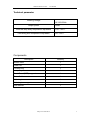
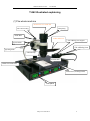
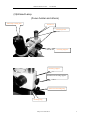
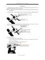
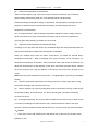
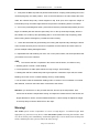
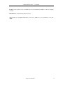
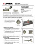
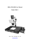
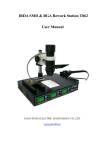
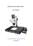
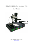
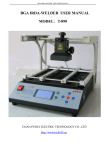
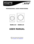
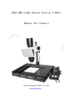
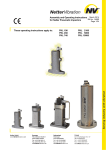
IRDA-WELDER User Manual Model: T862 Tai’an Puhui Electric Technology. CO., LTD. www.Tech168.cn IRDA-Workstation T862 User Manual CATALOGUE Features…………………………….……………..…………………….2 Technical Parameter and Components………………………………3 T-862 Illustrated Explaining……………………………………………4 (1)The Whole Machine………………………………………………4 (2)Front panel and Rear panel….…………………………………..5 (3)IR Lamp Body(Focus Holder and Others)…..…………………6 Infrared Work Station Unpacking and Assembly….…………………7 (1)Unpack the packaging……….………………………………….7 (2)Check the items.......................…………………………………7 (3)Install the cell guide...……………………………………………7 (4)Install the steady Ring…..……………………………………….7 (5)Assemble Wholly………………………………………………...7 (6)Connect the Tie Wire of the Lamp and the Iron……………….8 (7)Attach the IR Filter……………………………………………….8 T-862 Operation method………...………………………………….…9 1. Open the machine………..………………………………………9 2. Remove the chip…………..……………………………………10 3. Soldering the chip………………………………..………..……10 4. The use of the 936 searing iron……………………………..11 Maintenance and Warning.…………………………………..………12 Http://www.tech168.cn 1 IRDA-Workstation T862 User Manual Features Unlike Air Re-Work systems, The T-862 uses an Infrared source and optics to target heat to individual components without dislodging other SMT parts by way of eddies air currents. Infrared soldering technology with independent exploration capabilities via the focus lenses which is included in the package. Technician focused infrared heat is easy to target most component removal/replacement and re-work. The Workstation has a 80 X120mm a 600W controlled Pre-heating System. Infrared heat source bulbs are long-lived, in-expensive and easily replaced. Processor controlled set-point regulated temperatures with thermocouple feed-back. Integrated and adjustable Infrared (IR) eye protection. Can suitable for the entire component, especially Micro BGA component. The T-862 system also contains a temperature controlled touch-up iron and stand. Extra soldering tools are not necessary to solder/unsolder and re-work Surface Mount Technology (SMT) components18*18cm in size Training is illustrated in factory provided video. Http://www.tech168.cn 2 IRDA-Workstation T862 User Manual Technical parameter Working Voltage Output power AC220V/50Hz AC110V/60Hz 600W Infra-red lamp body temperature adjustable 100℃-350℃ Preheating dish temperature adjustable 60℃-200℃ Components Description Quantity Welder base 1 Guide rod 1 Locating ring 1 Lamp assy 1 Circuit Board(PCB) support 1 Power Cable 1 Soldering iron 1 Soldering iron support 1 User Manual 1 Http://www.tech168.cn 3 IRDA-Workstation T862 User Manual T-862 illustrated explaining (1)The whole machine Protection Cover of the fan The end covering Lamp body Guide Rod Filter and Cover 936 soldering iron support Focus holder 钮 936 soldering iron Focusing knob 钮 Infrared lamp Preheat dish Holder for PCB board Welder base (working bench) Front panel Http://www.tech168.cn 4 IRDA-Workstation T862 User Manual (2)Front Panel 936 temperature display Infrared lamp Peak temperature Sol-preheater Peak temperature display Infrared Lamp Switch Touch-UP Iron Switch Preheater plate Switch Temperature level regulation Button Back Panel Power Input Connecter for 936 soldering Iron Fuse Connecter for infrared Lamp Power Switch Http://www.tech168.cn 5 IRDA-Workstation T862 User Manual (3)Infrared Lamp (Focus holder and others) IR Lamp Cooling Fan Guide rod Focusing knob Focusing Support Focusing support Pinch nut of focusing support Pinch nut of locating ring Locating ring Http://www.tech168.cn 6 IRDA-Workstation T862 User Manual Installation 1. Install the guide rod. Loosen the pinch nut of focusing support; put the guide rod in according to the direction of arrow icon pointing. Note: The Infrared Head, Body Mounting and Focus Assembly will be installed in the T-862 chassis later. 2. Inventory all Items, confirm no parts are missing. If parts are missing call 0086 538 6138575 The direction of guide rod Guide rod 3. Put the locating ring in. Loosen the pinch nut of locating ring; put the locating ring in according to the arrow icon pointing and fasten the nut to the appropriate height. Locating ring The direction of the locating ring 4. Machine Assembled □ Loosen the pinch nut of focusing support. □ Pick up focusing support; make the guide rod aim at the corresponding nut on the base, then rotate the guide rod. □ Fasten the focusing support by rotating pinch nut of it. □ Rip off the protective film of the filter. Direction of Rotation . Http://www.tech168.cn 7 IRDA-Workstation T862 User Manual 5. Connecting the wire of the lamp body. Get the adapter of connecting wire plug in the socket of infrared lamp connecting wire. Rotate set screw clockwise. 6. Attach IR Eye protective filter with the supplied screw and nut. T-862 Operation Infrared Lamp Body Circuit Board Support Welder base(work bench) 1、Starting: (1) Inspect the infrared lamp body, temperature sensor and power line and see if they are in good connection, (2) Turn on the power switch, then use self-checking first( The previous setting value demonstrated on the keyboard display monitor after you turn on the machine) (3) The front panel has three switches, Controlling hot melt adhesive disks, infrared lamp body and lead-free 936 soldering iron separately. (4) Press temperature level regulation button, can adjust every window setting value, ∧ represents on rising, ∨ represents reduced setting value, then the machine automatically stored the data after you press the button. It will display the current value in the next time when you turn on the machine. 2、Unsolder: (1)、 PCB placement and Infrared lamp body height adjustment: Put PCB on the corresponding notch in PCB Support, and adjust the pinch nut of locating ring and focusing support, make the infrared lamp body vertical alignment chip focal spot; then adjust the height of infrared lamp body, the ideal height between lamp and the unsoldering article is 20-30mm. Http://www.tech168.cn 8 IRDA-Workstation T862 User Manual (2) 、Setting the temperature of preheat dish: When unsolder lead-free chip, if the area of chip is more than 30x30mm and coated with rubber sealing waterproofing solid chip, must preheat PCB to melt glue firstly. General preheating temperature setting: for lead board, set temperature preheating 120-140 degrees, for lead-free PCB, set temperature preheating 160-200 degrees (this is the temperature of preheat dish). Turn on preheat chassis, make the display temperature stability around the setting value for about 3-5 minutes, then open infrared lamp heating the chip to arrive the requirement of removing glue and preheating, unsolder can be succeed. (3)、 Adjust the peak temperature of Infrared lamp body According to the chip sizes that need to be unsoldered adjust the lamp peak temperature of output, peak temperature between100-350 degrees is adjustable. When you unsolder chips which are about 15mm*15mm, you adjust the infrared lamp’s temperature to160-240℃, When unsoldering chips which are about 15*15—30*30mm, you adjust the infrared lamp’s at 240-320℃. When the areas of the chips more than 30x30mm you adjust the infrared lamp’s at 350 degrees, at this time, the infrared ray lights directly, infrared ray is the strongest (you need pay attention to the timing, and prevent from burning out the chips). Note: When the peak temperature is below 248 ℃, lamplight will be continuously, intermittent heating. (4)、 After the lamp holder replacement, according to the size of chips, adjust the focusing knob. Make the bright spot cover the whole chip. (5)、 Before unsolder chip, inject a small quantity of flux in the bottom of a chip or side can get good solder beading, at the same time, can protect bonding pad, and make unsoldering process more fluent. (6)、At the appropriate time, the tin points will be melted then remove the chip. It takes 20-40s or so when unsoldering less than15x15mm chips, it takes 30-60s,if the area of the chips between 15x15mm-30x30mm,it takes 60-90s,when the area of the chips more than 30x30mm. 3、Reflow: 1、 Clean pad: use the 936 soldering irons with WICK, flux to clean the pad. Prepare some liquid flux to use. Http://www.tech168.cn 9 IRDA-Workstation T862 User Manual 2、 First place the BGA chip that has planted solder bead or scraping solder paste good on the cleaned pad gently and Para position. Then fix the PCB board on the stent, adjust the stent, make the infrared lamp body vertical alignment chip focal spot; then adjust the height of infrared lamp body, the ideal height between lamp and the unsoldering article is 20-30mm. 3、Turn on the preheating dish switch, preheat until reach the preheated temperature (flux has begun to infiltrate pad and reductive pad oxide).Turn on the top heat lamps rapidly, after the flux volatile, turn off the top and preheating plate in 10 seconds after chip morphology. After board cooling below 100 degrees, put aside the board cooling. 4、 Clean the board that has good welding and cooling with liquid and dry cleaning the board. Then can take electricity test. If the test is not passed, find the reasons and clear reason to prevent multiple welding damaged boards. 5、Rapid lead-free 936 soldering iron uses: turn on the power switch, set the temperature that you needed, turn on the switches. ***. The reasons that are not passed in the electric test as follows, for reference only 1. Bonding pad is not clean, virtual welding 2. The temperature of solder paste reflow isn't high enough, virtual welding 3. Heating fast and flux volatile fast produce gas explosion caused the chips shift, the solder beading connection circuit or solder beading vacancy virtual welding. 4. You shouldn’t wash the board after welding until it is cooled, if it is not washed or not dried after washed, it will burn the board when connected to the electric. Attention: you should turn on the pre-heat dish first, and set-up the temperature, wait 3-5minutes to allow the temperature steady, and adjust the measurement of the facular, the largest diameter is 30mm, and the smallest diameter is 15mm.usually we adjust the height of the lamp body 20-30mm distance from the chips. Warning! The T-862 System creates temperatures in excess of high degrees via Infrared Light. Wear appropriate eye protection or any device within The T-862 system when using this machine. After use, do not cut the power immediately, confirm the light body is cool-to-touch, Turn off the power switch, and then place the system in airiness & safety storage. Http://www.tech168.cn 10 IRDA-Workstation T862 User Manual Do not use this system or any associated device in an environment conducive to fire or electrical overload. Disconnect the AC Power Plug when not in use. When using, it is of high temperature, do not allow children or the un-trained to touch the T-862. Http://www.tech168.cn 11