1
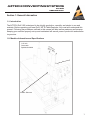
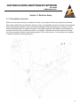
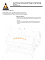
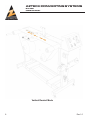
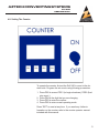
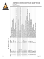
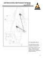
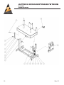
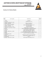
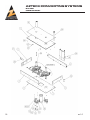
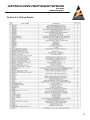
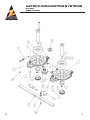
AZTECH CONVERTING SYSTEMS
212 W Lodge Drive
TEMPE, AZ 85283
PHONE (480) 951-8351
FAX (480) 998-5409
www.aztechconverting.com
0l
9 a
X u
n
L
a
L
O er M
R s
U
AZTECH CONVERTING SYSTEMS
ROLL X90
USER MANUAL
TABLE OF CONTENTS
SECTION 1: GENERAL INFORMATION
1-4
SECTION 2: MACHINE INSTALLATION
4
SECTION 3: MACHINE SETUP
5-9
SECTION 4: MACHINE OPERATION
10-13
SECTION 5: MAINTENANCE
14-21
SECTION 6: WARRENTY
22
AZTECH CONVERTING SYSTEMS
Roll X90
USER MANUAL
Section 1: General Information
1-1: Introduction
The AZTECH Roll X 90 is designed to be a highly productive, versatile, and simple to use and
maintain. Before operating your new Roll X 90 Tilt Table Rewinder, fully read and understand this
manual. Following the procedures outlined in this manual will help assure maximum performance.
Keeping your machine properly set-up and maintained will assure years of productive and satisfactory service.
1-2: Machine Information and Specifications
1-10 Inch
Convertech
Spindles Available
Co
Sp nvinie
lice
n
-Ta t
ble
ra
ble
mma
Prog
ter
Coun
22 Max. Diameter
1
AZTECH CONVERTING SYSTEMS
Roll X90
USER MANUAL
FRONT LAYOUT
2
Rev 1.0
AZTECH CONVERTING SYSTEMS
Roll X90
USER MANUAL
SIDE LAYOUT
ALLOW AT LEAST 3 FEET
OF WORKING CLEARANCE
AROUND THE PERIMETER
OF THE MACHINE
3
AZTECH CONVERTING SYSTEMS
Roll X90
USER MANUAL
1-3: Safety
The Roll X 90 Tilt Table is designed to operate at high rates of speed, employing rollers and other
moving parts. Operators must keep their hands clear of the machine when in operation. Making
all operators aware of potential safety hazards will help minimize any chance of operator injury.
Section 2: Machine Installation
2-1: Preparation
It is important that your Roll X90 Tilt Table Rewinder situated on solid and level ground. Make sure
that site allows for access to machine from all 4 sides. If the machine is placed on unstable or
un-level ground, it may tip over risking damage or serious personal injury.
2-2: Un-crating Machine
To avoid damage to your new Roll X90 Tilt Table Rewinder, first remove the cover by removing all
screws, then remove one of the 2 long side panels to expose machine. Remove all lag bolts which
hold the machine to the base. Remove all boxes and parts inside crate.
2-3: Removal and Positioning
It is critical that the Roll X90 Tilt Table Rewinder be removed from the crate using a fork lift, making
sure that the forks fit directly inside the 2 slots at base of the machine. Lift and remove from crate,
and if equipped with adjustable feet, thread all 4 feet into threaded holes at machine’s base, and
lower into desired position. Machine may be leveled by turning adjustable feet until level.
2-4: Electrical and Pneumatic Connections
Your Roll X90 Tilt Table Rewinder requires 15A 115VAC and 90PSI high pressure air service. Connections to the machine are provided on whips. Connect the electrical cord to a suitable outlet and
use the quick-connect to supply air to the machine.
4
Rev 1.0
AZTECH CONVERTING SYSTEMS
Roll X90
USER MANUAL
Section 3: Machine Setup
3-1: Testing Before Operation
Make sure the area around your machine is clear of any objects which may impair the machine.
Also inspect and make sure all belts, pulleys, rollers, and spindles are free and clear of any objects
which may impede operation, and risk machine damage. Before threading your machine, accelerate and decelerate your machine through a full range of speeds, and make sure acceleration is
smooth and free of any unnatural sounds or movements. Operate the spindle switches, making
sure the pneumatic system is performing properly. Then turn power on, run machine at low speed
to assure machine is working properly.
5
AZTECH CONVERTING SYSTEMS
Roll X90
USER MANUAL
3-2: Webbing the Machine
Proper webbing of your Roll X90 Tilt Table is vital to optimal
machine performane. Paths are shown on the followind pages
to accomplish different converting tasks with various substrates.
To Web the Machine
1. Make sure the unwind and rewind switch is in the off position.
2. Assure that both splice-table clamps are released into the up
positon.
3. Load roll onto unwind spindle and carefully thread the web
through the machine makind sure to follow the web paths
shown.
6
Rev 1.0
AZTECH CONVERTING SYSTEMS
Roll X90
USER MANUAL
Horizontal Rewind Mode
7
AZTECH CONVERTING SYSTEMS
Roll X90
USER MANUAL
Vertical Rewind Mode
8
Rev 1.0
AZTECH CONVERTING SYSTEMS
Roll X90
USER MANUAL
3-4: Splice Table Operation
The splice table on your Roll X90 is located just above the Unwind
Station, just after the optional Inspection Tower. To operate the
Splice Table, simply follow the following steps:
EL
G
TIN
N
AN
CH
IT
SL
WEB CLAMPS
1. Turn off machine and engage both web clamps.
2. Using a razor blade, carefully cut the web along the slicing channel. Disengage the clamp nearest the unwind roll. Be sure to leave the other clamp engaged.
3. After waste has been removed, pull through new web, carefully align with web, and lower the
handle to hold.
4. Again using a razor blade, cut the web, discard waste, pull tape under webs, fold to secure and
cut tape.
5. Disengage both clamps.
9
AZTECH CONVERTING SYSTEMS
Roll X90
USER MANUAL
Section 4: Machine Operation
4-1: Operator Control Panel
Pilot Light
E-STOP
Speed Pot
Label/Inch
Switch
START PB
STOP PB
DISCONECT
90deg Switch
Pilot Light
10
Rev 1.0
AZTECH CONVERTING SYSTEMS
Roll X90
USER MANUAL
4-2: Setting The Counter
PB1
PB2
PB3
PB4
To operate the counter, first set the Roll X90 to count in the desired units. Program the set counts using folowing proceedure:
1. Press PB2 to access PRS1 (to begin slowdown), PRS2 (final
stop count.)
2. Press PB4 to the digit that you are changing
3. Press PB3 to enter the number
4. Press PB2 to enter normal operating mode
Press “RST” to reset at any time. If you need any further information on the counter, refer to the counter operator manual
included with this manual.
11
AZTECH CONVERTING SYSTEMS
4-3: Counter Program
Roll X90
USER MANUAL
12
Rev 1.0
AZTECH CONVERTING SYSTEMS
Roll X90
USER MANUAL
Adjustment
Knobs
4-3: Setting Web Tension
To set web tension, siimply
turn the air-controlled valves
clockwise for more tension
and counter-clockwise for less
tension. Taking note of the
settings on the provided air
gauges will aissist in setting the
pressures correctly.
13
AZTECH CONVERTING SYSTEMS
Roll X90
USER MANUAL
Section 5: Troubleshooting/Maintenance
5-1: Why doesn’t the machine turn on?
First check to make sure that the main power switch is turned on. Then make sure that the emergency stop button is disengaged. If this does not remedy to situation, check the fuses inside the
electrical enclosure.
5-2: The counter is not counting accurately.
Make sure that counter wheel riding on the idler wheel is free of dust or debris and is not visibly
damaged.
5-3: Why is the counter not counting in inches?
Make sure that the counter sensor is flashing red when the wheel turns, assuring that the sensor is
powered and operating. If equipped with the optional label sensor, assure that the switch is set to
“INCHES”.
5-4: Maintenance Schedule
Daily:
-Check the airline and power cord for frays and damage
-Check to assure that the E-STOP functions correctly
-Clean machine after use, use compressed air to clean debris from the rewind spindle
Monthy:
-Check drive belt for wear
-Lubricate bearings
14
Rev 1.0
AZTECH CONVERTING SYSTEMS
Roll X90
USER MANUAL
5-5: Electrical Schematic
15
AZTECH CONVERTING SYSTEMS
Roll X90
USER MANUAL
16
Rev 1.0
AZTECH CONVERTING SYSTEMS
Roll X90
USER MANUAL
Section 5-6: Station Details
17
AZTECH CONVERTING SYSTEMS
Roll X90
USER MANUAL
18
Rev 1.0
AZTECH CONVERTING SYSTEMS
Roll X90
USER MANUAL
Section 5-6: Station Details
19
AZTECH CONVERTING SYSTEMS
Roll X90
USER MANUAL
20
Rev 1.0
AZTECH CONVERTING SYSTEMS
Roll X90
USER MANUAL
Section 5-6: Station Details
21
AZTECH CONVERTING SYSTEMS
Roll X90
USER MANUAL
Section 6: Warranties and Service
6-1: Warranties & Provisions
WARRANTIES: All equipment manufactured and sold by AZTECH Converting Systems (Seller) is
warranted to be free of defective materials and workmanship under normal use and service for a
period of one (1) year from the date of delivery to Buyer's premises. All commercial components not
manufactured by Seller carry the original manufacturer's warranty. At Seller's discretion, Seller may
provide on-site warranty service for a period of ninety (90) days from the aforementioned date.
REMEDIES If within the Warranty Period any such Equipment is proven to Seller's satisfaction to
be defective in either material or workmanship, Seller, at its sole discretion, shall (a) repair or replace defective parts on the Equipment at Seller's cost, or (b) grant a reasonable allowance on
account of such a breach. If within the Warranty Period the Seller receives notice from Buyer of
defects in parts or materials. Seller will ship (ground, prepaid) replacement parts) and invoice Buyer
for the full cost of the replacement parts). Buyer will receive a Return Authorization (RA) from seller,
and return defective parts or materials to Seller, who at its sole discretion shall determine whether
defective parts or materials are or are not subject to exclusion from this warranty as provided herein. Any defective parts or material not excluded from the Warranty Period will then be fully credited
to Buyer.
EXCLUSIONS
THE FOLLOWING ITEMS ARE EXCLUDED FROM THIS WARRANTY:
• Defects or damage caused by careless or improper use.
• Parts that need periodic replacement from wear during normal operation.
• Routine maintenance and adjustment.
• Failure or damage caused by improper
installation or inadequate maintenance by Buyer.
• Failure or damage caused by equipment modifications by Buyer.
• Equipment damage resulting from an accident, or abnormal conditions of operation.
DISCLAIMER OR WARRANTY
NO OTHER WARRANTY IS EXPRESSED OR IMPLIED INCLUDING WARRANTIES OF MERCHANTABILITY AND FITNESS FOR ANY PARTICULAR PURPOSE. SELLER IS NOT LIABLE
FOR INCIDENTAL OR CONSEQUENTIAL DAMAGE SUCH AS, BUT NOT LIMITED TO LOSS IN
PROFITS, LOSS OF USE OF EQUIPMENT, OR INCREASED IN OPERATING COSTS OR EXPENSES.
6-2: Technical Service
In the event that your X90 is not functioning properly or if you have any technical questions, an AZTECH Technical Service representative is available to assist you. Contact information is as follows:
Phone:
Fax:
E-Mail:
22
1-480-951-8351
1-800-829-8351
1-480-998-5409
[email protected]
Rev 1.0