1
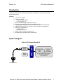
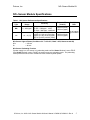
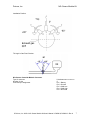
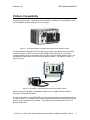
NOx Sensor Module Kit User’s Manual
D000018 Rev A
D000019 Rev A
January 2009
Drivven, Inc. • 12001 Network Blvd, Bldg E, Suite 110 • San Antonio, Texas 78249 • USA
Phone : 210.248.9308
Web : www.drivven.com , E-mail : [email protected]
Drivven, Inc.
NOx Sensor Module Kit
Contents Introduction ......................................................................................................................... 3 System Diagram .................................................................................................................. 3 Hardware ............................................................................................................................. 4 Powering the Hardware....................................................................................................... 4 NOx Sensor Module Specifications .................................................................................... 5 Platform Compatibility ....................................................................................................... 8 Software .............................................................................................................................. 9 Creating a LabVIEW Project ............................................................................................ 10 Exploring the Example Project ......................................................................................... 12 Sub VI Documentation ..................................................................................................... 17 © Drivven, Inc. 2009 • NOx Sensor Module Kit User’s Manual • D000018, D000019 • Rev A
2
Drivven, Inc.
NOx Sensor Module Kit
Introduction
The Drivven cRIO NOx Sensor Module Kit provides an interface for one or two NOx and O2
exhaust gas sensors.
Features:
¾
¾
¾
¾
¾
¾
¾
¾
¾
1-Ch. or 2 Ch. system
Triple signal output:
o NOx concentration (ppm)
o O2 concentration (%)
Sensor controller supply voltage of 12V to 32V
Reverse battery protection on sensor controller module
Integrated with LabVIEW FPGA and LabVIEW RT to provide real-time data
LabVIEW FPGA and RT VIs included for quick integration with application
Wide range of applications:
o Gasoline / Diesel
o Passenger car / Truck
Helps to achieve emissions requirements
Includes sensor controller module connector kit
System Diagram
Drivven NOx Sensor Module Kit
NI 9853 for CompactRIO
CAN 1
Sensor
Controller
Module
CAN 2
Additional
Optional
Sensor
LabVIEW FPGA
Interface to
NI 9853
LabVIEW RT
Interface to
LabVIEW FPGA
Driv v en Integration Softw are Support
Prov ides NOx and O2 Data
to User Application
NOx and O2 Sensor
© Drivven, Inc. 2009 • NOx Sensor Module Kit User’s Manual • D000018, D000019 • Rev A
3
Drivven, Inc.
NOx Sensor Module Kit
Hardware
This kit provides the following hardware:
1 Continental Smart NOx Sensor with integrated sensor controller module
1 Sensor bung
1 Connector kit for NOx sensor controller module
1 National Instruments NI-9853 CompactRIO CAN module
The end user must provide wiring for connecting the sensor controller module to a power supply
and the NI 9853 CAN module. A connector kit is provided for the sensor controller interface. The
end user must provide a DB-9 connector kit for connecting to the NI 9853 CAN module. Any DB9 connector system may be used. Drivven recommends the following DB-9 connector parts and
tools available from several electronics parts distributors (Allied, Mouser, Digikey, etc.).
Table 1. Connector parts list
Description
AMP HDP-20 Series 109 9P Receptacle Housing
AMP HDP-20 Series 109 Crimp Socket Contact
Norcomp D-Sub Connector Hood, 9P 45 Degree
AMP D-Sub Insert/Extract Tool
Paladin D-Sub 4-Indent Crimp Tool 26-20 AWG
Mfr.’s Part #
1757820-1
205090-1
971-009-020R121
91067-2
1440
CAN network wiring guidelines must be followed. Please refer to the operating instructions
provided with the NI 9853 CAN module. A terminating resistor of approximately 120 ohms must
be connected between CAN High and CAN Low pins.
Powering the Hardware
The NOx Sensor Controller Module requires power from a range of 12V to 32V with a continuous
current of 0.6A and a peak current of 12A. The maximum power requirement is 20W.
For power requirements of the NI 9853 CompactRIO CAN module, please refer to the National
Instruments NI 9853 Operating Instructions.
© Drivven, Inc. 2009 • NOx Sensor Module Kit User’s Manual • D000018, D000019 • Rev A
4
Drivven, Inc.
NOx Sensor Module Kit
NOx Sensor Module Specifications
Table 1. NOx Sensor Performance Specifications
Output
Measurement
Accuracy
Type
Range
NOx
O2
0 – 3000 ppm
-12 – 21 [%]
@ 0 ppm:
±10 ppm
@ 100 – 1500 ppm: ±10%
@ 1500 – 3000 ppm: undefined
@ λ=0.90: ±1.4% (fresh)
@ 0% (λ=1.00): ±0.13% (fresh)
@ 0% (λ=1.00): ±0.25% (aged)
@13% (λ=2.65): ±0.32% (fresh)
Response Time
(33-66%)
Data Update
Rate
1300 ms (fresh)
1650 ms (aged)
1000 ms (fresh)
1300 ms (aged)
50 ms interval
@ 250 kBaud
NOx Sensor Light-off times (Conditions: Air T = 25 ±5°C, BattV = 28V, Heater turned ON)
NOx
< 100 sec
O2
< 80 sec
NOx Sensor Preheating Function
If power supply is on, the sensor is in preheating mode until the Heater Boolean is set to TRUE.
If the Heater Boolean is set to FALSE, the sensor returns to preheating mode. The preheating
mode protects the sensor from mechanical cracks caused by water splash.
© Drivven, Inc. 2009 • NOx Sensor Module Kit User’s Manual • D000018, D000019 • Rev A
5
Drivven, Inc.
NOx Sensor Module Kit
NOx Sensor Operating Temperature Ranges
Minimum sensor module controller temperature
-40°C
Maximum sensor module controller temperature
105°C
Sensor module controller temperature range of 85°C to 100°C allowed for up to 10 minutes
Minimum storage temperature
Maximum storage temperature
Maximum storage time
-40°C
120°C
2 years
Maximum exhaust gas temperature
Exhaust gas temperature of 950°C allowed up to 100 hours
800°C
Maximum sensor hexagon screw temperature
620°C
Sensor hexagon screw temperature of 650°C allowed for up to 100 hours
Maximum sensor grommet temperature
200°C
Sensor grommet temperature of 230°C allowed for up to 100 hours
Minimum preheating sensor temperature
Maximum preheating sensor temperature
80°C
120°C
Lifespan approved by life cycle pattern
2000 hours or 120K miles
NOx Sensor Electrical Characteristics
NOx Sensor Supply Voltage
Minimum supply voltage
Maximum supply voltage
If supply voltage > 32 V, sensor is not operated
12 V
32 V
NOx Sensor Supply Current
Average supply current
Peak supply current at switch on
Inrush current
0.6 A
12 A
20 A
Supply Power
Maximum supply power
20 W
NOx Sensor Misc.
Thread Torque
50 Nm
Lubrication
Anti-Seize Compound
© Drivven, Inc. 2009 • NOx Sensor Module Kit User’s Manual • D000018, D000019 • Rev A
6
Drivven, Inc.
NOx Sensor Module Kit
Installation Position:
Tilt Angle in Gas Flow Direction:
NOx Sensor Controller Module Connector
Type of connector
Number of pins
Connector pin assignment
Hirschmann MLK 872-860-501
5
Pin 1: Battery
Pin 2: Ground
Pin 3: CAN Low
Pin 4: CAN High
Pin 5: Not Used
© Drivven, Inc. 2009 • NOx Sensor Module Kit User’s Manual • D000018, D000019 • Rev A
7
Drivven, Inc.
NOx Sensor Module Kit
Platform Compatibility
CompactRIO modules from National Instruments are compatible within two different platforms
from National Instruments. One platform is CompactRIO, consisting of a CompactRIO controller
and CompactRIO chassis as shown in Figure 1a below.
Figure 1a. CompactRIO platform compatible with Drivven/NI CompactRIO modules.
The other platform is National Instruments PXI which consists of any National Instruments PXI
chassis along with a PXI RT controller and PXI-78xxR R-Series FPGA card. An R-Series
expansion chassis must be connected to the PXI FPGA card via a SHC68-68-RDIO cable. The
CompactRIO modules insert into the R-Series expansion chassis. This platform is shown in
Figure 1b below.
Figure 1b. PXI platform compatible with Drivven/NI CompactRIO modules.
National Instruments NI 9853 CompactRIO modules are not compatible with the National
Instruments CompactDAQ chassis.
Drivven CompactRIO modules REQUIRE one of the hardware support systems described above
in order to function. The modules may not be used by themselves and/or interfaced to third party
devices at the backplane HD15 connector. These efforts will not be supported by Drivven or
National Instruments.
© Drivven, Inc. 2009 • NOx Sensor Module Kit User’s Manual • D000018, D000019 • Rev A
8
Drivven, Inc.
NOx Sensor Module Kit
Software
The NOx Sensor Module Kit is provided with an installer package which may be downloaded from
Drivven’s Sharepoint website after obtaining login access from Drivven. User’s may go to
http://portal.drivven.com/SoftwareDownload and enter the provided username and password to
gain access to the specific product installer packages which have been purchased. The installer
packages are executables which should be run on the intended development computer, having
LabVIEW development tools installed. After installing the package, a “Start->Programs->Drivven>ProductRelease” menu item will be added to the desktop. The specific product will have an
example LabVIEW project appear under the “Examples” menu and the user manual will appear
under the “Manuals” menu. User’s may copy and open the example project to experiment with
the module or use as a starting point for a new application. All software files, example projects
and documentation are installed to:
C:\Program Files\National Instruments\LabVIEW X.X\vi.lib\addons\DrivvenProductRelease\.
When working with block diagrams, user’s will notice a “Drivven” function palette added to the
standard LabVIEW palette, specific for the RT or FPGA target. VIs for a specific Drivven product
will be categorized according to product name. Also, some Drivven products will install RT and
FPGA VIs under a “General” function palette which is intended to be used across multiple
products.
Requirements
The Drivven VIs require:
¾ LabVIEW 8.5 Full Development or later
¾ LabVIEW RT Module 8.5 or later
¾ LabVIEW FPGA Module 8.5 or later
¾ NI-RIO 2.4 or later
The NOx Sensor Module Kit is provided with both a LabVIEW FPGA VI for interfacing to the NI
cRIO 9853 CAN module and a LabVIEW RT VI for interfacing with the FPGA VI and managing
and reporting sensor results.
Figure 2. nox_revx.vi and nox_rt_revx.vi icons with leads.
© Drivven, Inc. 2009 • NOx Sensor Module Kit User’s Manual • D000018, D000019 • Rev A
9
Drivven, Inc.
NOx Sensor Module Kit
Creating a LabVIEW Project
Drivven recommends working from the provided example application as a starting point for
learning the use of the Drivven software blocks. However, the following section describes starting
a LabVIEW project from scratch and adding a CompactRIO module.
1.) Install the Drivven software by running the installer executable and accepting the
software license agreement.
2.) Restart LabVIEW, if previously running, and create a new LabVIEW project.
3.) Give the new project a name by clicking the “Save Project” button on the project toolbar.
4.) Right click on the highest item in the project hierarchy (“Project:…”) and navigate to
“New->Targets and Devices…”
5.) Within the “Add Targets and Devices…” dialog, select the appropriate radio button,
depending on whether you already have an existing powered and configured RT target
on the network or if you are adding a new RT target which is not present yet on the
network.
a. Existing Target or Device
i. Expand the appropriate category in the “Targets and Devices” list to see
the discovered targets in that category.
ii. Double-click the desired target to add it to your project.
b. New Target or Device
i. Expand the appropriate category in the “Targets and Devices” list to see
all possible targets within that category.
ii. Double-click the desired target to add it to your project.
6.) If the new RT target is not currently on the network, right-click on the RT target within the
project and open the properties dialog to set the IP address or DNS name if necessary.
7.) Right-click on the RT target within the project and navigate to “New->Targets and
Devices…”
8.) Within the “Add Targets and Devices…” dialog, select the appropriate radio button,
depending on whether you already have an existing FPGA target connected to an
existing RT target or if you are adding a new FPGA target which is not present yet.
a. Existing Target or Device
i. Expand the appropriate category in the “Targets and Devices” list to see
the discovered FPGA targets in that category.
ii. Double-click the desired target to add it to your project.
b. New Target or Device
i. Expand the appropriate category in the “Targets and Devices” list to see
all possible targets within that category
ii. Double-click the desired target to add it to your project.
9.) If the new FPGA target was not currently in the system, right-click on the FPGA target
within the project and open the properties dialog to set the resource name if necessary.
The resource name can be found from MAX when connected to the actual remote
system.
10.) If the FPGA target is a PXI or PCI card, then an R Series expansion chassis must be
added under the FPGA target. This is done by right-clicking on the FPGA target and
navigating to “New->R Series Expansion Chassis”. Within the following dialog, select the
appropriate FPGA connector to which the chassis will be connected. A unique name for
the chassis may also be specified.
11.) Right click on the R-Series expansion chassis or cRIO FPGA target chassis and navigate
to “New->C Series Modules…”
12.) Select the “New Target or Device” radio button and double-click on the “C Series Module”
in the “Targets and Devices” list. In the following dialog, select the desired CompactRIO
module at the bottom of the “Module Type” list. Select the appropriate module location.
Finally, specify an appropriate name for the module, which will later appear in the FPGA
© Drivven, Inc. 2009 • NOx Sensor Module Kit User’s Manual • D000018, D000019 • Rev A
10
Drivven, Inc.
NOx Sensor Module Kit
I/O nodes in the FPGA block diagram. Having meaningful module names is important for
preventing coding mistakes.
13.) After adding a module to the project, a folder will automatically be added to the project
having the same module name given in the module configuration dialog. The folder will
contain the FPGA I/O nodes for the module slot. These I/O nodes can be selected in the
block diagram when connecting the module I/O to various portions of the FPGA code.
© Drivven, Inc. 2009 • NOx Sensor Module Kit User’s Manual • D000018, D000019 • Rev A
11
Drivven, Inc.
NOx Sensor Module Kit
Exploring the Example Project
Figure 3. Example expanded project explorer of NOx_Example.lvproj.
Use the NOx_Example_FPGA.vi as an example to implement a NOx sensor interface into your
own application. Just copy and paste one of the while loops, as shown below in figure 4, into
your application.
© Drivven, Inc. 2009 • NOx Sensor Module Kit User’s Manual • D000018, D000019 • Rev A
12
Drivven, Inc.
NOx Sensor Module Kit
Figure 4. Example block diagram implementation of NOx VI.
Please follow the guidelines below for adding the nox_reva.vi to your FPGA application:
1.)
2.)
3.)
4.)
5.)
6.)
7.)
8.)
The NOx sensor interface vi, nox_reva.vi, should be placed in its own while loop.
Do not place more than one NOx sensor interface vi within the same while loop.
Do not place the NOx sensor interface within a single cycle loop.
The cRIO 9853 CAN Module properties may be configured by right-clicking on the
module within the project explorer. The properties should be set to the following:
a. Baud Rate = 250 Kbps
b. Auto Start = Checked
c. Listen Only = Unchecked
d. Input Timeout > 50 msec (100 msec recommended)
e. Output Timeout < 10 msec (0 recommended)
f. Input Filter = Receive All
Other CAN nodes may be connected to the same CAN bus, as long as they conform to
the above properties.
Use the CANX Restart button to re-establish connection with the NOx sensor module if
the CAN bus is disconnected and then connected again.
NOx bits must be converted to NOx ppm at the RT level according to:
a. NOx ppm = (bits * 0.05) – 200.
b. Data type of bits is I16.
c. The above conversion is performed by nox_rt_reva.vi.
O2 bits must be converted to O2% at the RT level according to:
a. O2% = (bits * 0.000514) – 12.
b. Data type of bits is U16.
c. The above conversion is performed by nox_rt_reva.vi.
Right click on the NI 9853 module within your project explorer and select Properties. A dialog
will open and allow you to make the CAN module settings listed in item 4 above. The property
dialogs are shown below in figure 5a and 5b.
© Drivven, Inc. 2009 • NOx Sensor Module Kit User’s Manual • D000018, D000019 • Rev A
13
Drivven, Inc.
NOx Sensor Module Kit
Figure 5a. Top level property dialog for NI 9853 module.
© Drivven, Inc. 2009 • NOx Sensor Module Kit User’s Manual • D000018, D000019 • Rev A
14
Drivven, Inc.
NOx Sensor Module Kit
Figure 5b. Advanced property dialog for NI 9853 module.
© Drivven, Inc. 2009 • NOx Sensor Module Kit User’s Manual • D000018, D000019 • Rev A
15
Drivven, Inc.
NOx Sensor Module Kit
If the CAN connection is expected to be disconnected at times while the NI 9853 CAN module is
active, then it may be necessary to implement a method to reset the CAN channel being used.
Do this by placing a FPGA I/O Method node which resets the CAN channel. The method node
should be placed within a case statement and selected by a boolean control. This boolean
control can be operated from the RT level programmatically.
Follow the NOx_Example_RT.vi to properly interface to your FPGA application. Use the
nox_rt_reva.vi to convert the data cluster from the nox_reva.vi to engineering units. It is not
necessary to access the TxID or RxID. They should never change. In fact, they can be replaced
by constants at the FPGA level. They are made available in case the default IDs change in the
NOx sensor module.
Figure 4. Example LabVIEW RT interface to LabVIEW FPGA NOx_Example_FPGA.vi.
© Drivven, Inc. 2009 • NOx Sensor Module Kit User’s Manual • D000018, D000019 • Rev A
16
Drivven, Inc.
NOx Sensor Module Kit
Sub VI Documentation
nox_reva.vi
The NOx sensor FPGA VI should be placed in its own while loop (as shown in the example).
Do not place more than one NOx sensor FPGA VI within the same while loop.
Do not place the NOx sensor FPGA VI within a single cycle loop.
The cRIO 9853 CAN Module properties should be set to the following:
Baud Rate = 250 Kbps
Auto Start = Checked
Listen Only = Unchecked
Input Timeout > 50 msec (100 msec recommended)
Output Timeout < 10 msec (0 recommended)
Input Filter = Receive All
Other CAN nodes may be connected to the same CAN bus, as long as they conform to the above
properties.
Use the FPGA CANX Restart method to re-establish connection with the NOx sensor module if
the CAN bus is disconnected and then connected again.
The following conversions are implemented at the RT level by the nox_rt_revx.vi.
NOx ppm = (bits * 0.05) - 200.
O2% = (bits * 0.000514) - 12.
TxID This is the Transmit ID for the NI CAN module.
This is the Receive ID for the NOx module.
By default the NOx module receive ID is 18FEDF00h, corresponding to PGN 65247.
This PGN contains the heater control command.
RxID This is the Receive ID for the NI CAN module. Only incoming messages with this
identifier will be processed.
This is the Transmit ID for the NOx module.
By default the NOx module transmit ID is 18F00F52h, corresponding to PGN 61455.
This PGN contains the NOx, O2 and status information from the NOx module.
Heater When TRUE, the NOx sensor module is requested to turn on the sensor heater
and begin controlling the sensor to high temperature. When FALSE, the NOx sensor
module is requested to place the heater circuit in preheating mode and begin controlling
to 80 C to 120 C.
CAN Error In Receives the error cluster wire from the error output terminal of the FPGA
© Drivven, Inc. 2009 • NOx Sensor Module Kit User’s Manual • D000018, D000019 • Rev A
17
Drivven, Inc.
NOx Sensor Module Kit
CAN I/O node (configured as "Read"). Right click on the FPGA CAN I/O Node and click
on Show Error Terminals.
CAN Data In Receives the cluster wire from the FPGA CAN I/O node. The FPGA CAN
I/O node should be configured as "Read".
NOxSensorData This cluster contains NOx, O2 and status data. This terminal should be
terminated with a cluster within the FPGA block diagram and made available to the
LabVIEW RT block diagram to be connected to the "NOxSensorData From FPGA" input
terminal of the nox_rt_revx.vi.
Update CAN Out Must be wired to the selector terminal of a case statement structure.
The TRUE case of the case statement must contain the FPGA CAN I/O node configured
for "Write".
CAN Data Out Output cluster to be wired to the FPGA CAN I/O node. The FPGA CAN
I/O node should be configured as "Write".
RxIDActual This is the actual received ID for the NI CAN module. This is useful to
determine what message IDs are actually being received.
© Drivven, Inc. 2009 • NOx Sensor Module Kit User’s Manual • D000018, D000019 • Rev A
18
Drivven, Inc.
NOx Sensor Module Kit
nox_rt_reva.vi
This VI is to be implemented at the RT level. It receives data from the FPGA VI
"NOxSensorData" output cluster and properly scales and offsets the results.
NOxSensorDataFromFPGA This terminal should be wired from the "NOxSensorData"
cluster output from the FPGA VI.
NOxSensorData Final processed result from the NOx Sensor.
NOx (ppm) Parts per million of oxides of nitrogen measured in the exhaust gas.
O2 (%) Percent oxygen content of the exhaust gas.
Sensor Supply Status Provides status information about the NOx sensor power
supply.
The following status messages are provided:
NOT IN RANGE
SUPPLY IN RANGE
ERROR
NOT AVAILABLE
Sensor Temperature Status Provides status information about the NOx sensor
heater temperature.
The following status messages are provided:
NOT AT TEMPERATURE
AT TEMPERATURE
ERROR
NOT AVAILABLE
NOx Signal Status Provides status information about the NOx sensor NOx ppm
measurement.
The following status messages are provided:
NOT VALID
VALID
ERROR
NOT AVAILABLE
O2 Signal Status Provides status information about the NOx sensor O2
measurement.
The following status messages are provided:
NOT VALID
VALID
ERROR
NOT AVAILABLE
Heater Mode Status Provides status information about the NOx sensor heater
control mode.
© Drivven, Inc. 2009 • NOx Sensor Module Kit User’s Manual • D000018, D000019 • Rev A
19
Drivven, Inc.
NOx Sensor Module Kit
The following status messages are provided:
AUTO MODE
HEATUP SLOPE 3 OR 4
HEATUP SLOPE 1 OR 2
HEATER OFF / PREHEAT
Heater Circuit Status Provides status information about the NOx sensor heater
circuit.
The following status messages are provided:
OPEN WIRE
SHORT CIRCUIT
NO ERROR.
NOx Circuit Status Provides status information about the NOx sensor NOx
measurement circuit.
The following status messages are provided:
OPEN WIRE
SHORT CIRCUIT
NO ERROR.
O2 Circuit Status Provides status information about the NOx sensor O2
measurement circuit.
The following status messages are provided:
OPEN WIRE
SHORT CIRCUIT
NO ERROR.
NOx Sensor Module Present Indicates whether the NOx sensor is powered,
properly connected, and detected on the CAN bus.
© Drivven, Inc. 2009 • NOx Sensor Module Kit User’s Manual • D000018, D000019 • Rev A
20