1
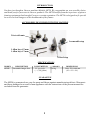
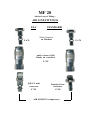
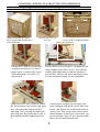
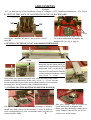
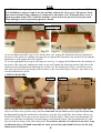
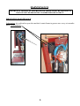
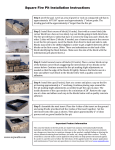
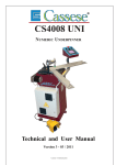
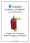
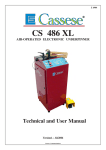
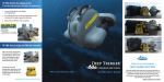
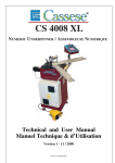
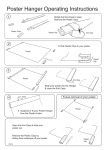
MF20
AIR OPERATED HANGER FIXER
TECHNICAL AND USER MANUAL
Version 1 au 04 / 2001
Cassese / Communication
MF20 – TECHNICAL AND USER MANUAL
CONTENTS
Page N°
INTRODUCTION
ACCESSORIES DELIVERED WITH THE MACHINE
1
SPECIFICATIONS / GUARANTEE
1a
OPTIONS
PUTTING INTO OPERATIONS
UNPACKING
2
SETTING-UP
ADJUSTMENTS
SETTING DISTANCE OF HANGER FROM TOP
SETTING CENTER OF LONG/SHORT DIMENSIONS
INSTALLING THE BOTTOM STAMP FOR HANGERS
3
USE
USE OF POSITION STOPS
4
FIXING HANGERS
MAINTENANCE
5
PREVENTIVE MAINTENANCE
MF 20 04 / 2001
INTRODUCTION
You have just bought a Cassese machine Multifix MF20. We congratulate on your sensible choice
and thank you for your trust in Cassese products. The MF20 benefits from the experience of picture
framing equipment that brought Cassese a certain reputation. The MF20 is designed to fix special
no-screw-no-nail hangers on the backboards of the frames.
ACCESSORIES DELIVERED WITH THE MACHINE
3 feet with nuts
1 removable stop
1 Allen key n°5 mm
1 Allen key n°3 mm
1 fixed stop
SPECIFICATIONS
MODEL
MF20P
DESCRIPTION
Pneumatic hanger fixer
CONSUMPTION
2 L per cycle
(= ½ US gallon)
WEIGHT
60 kg
DIMENSIONS
500 x 550 x 600 mm
(20’ x 22’ x 24’)
GUARANTEE
The MF20 is guaranteed one year for parts and labour against manufacturing defects. Wear parts
and those damaged as a result of non-appliance with the instructions of the present manual are
excluded from the guarantee.
1
ITEM
DESCRIPTION
EXPLANATIONS
ADVICE
1a
Z 7400
Stamp for hanger # 1401 With one rosette. Remaining flat,
thus ideal for volume framers and
for shrink-wrapping
Small frames
Z 7401
Stamp for hanger # 1409 Hinged (articulated) hanger for
French hanging systems
Small and medium sized frames
Z 7705
Stamp for hanger # 1413 Pivoting hanger ; can be used with
hanging wire and as D-ring
All sizes of frames and mirrors
Z 7397
Stamp for hanger # 1428 Same as # 1409 above but wider
Bigger and heavier frames
Z 7399
Stamp for hanger # 1439 With 4 rosettes
Heavy frames and mirrors
Z 7398
Stamp for hanger # 1490
Z 7933
Stamp for hanger # 2602 With 2 rosettes – Hanger area larger
than # 1490, thus easier to adjust for
consumer
Z 7739
Stamp for hanger LB
Hanger and support for a feet that
can be used as strut back (easel)
for photo frames
Sizes of feet for small and big
frames available
Z 6411
Accessories needed for
fixing strut back hinges
(easelbacks)
3 sizes of hinges available for strut
back photo frames: add one locator
part per size of hinge chosen
Add Locator # 32 for most popular
medium sized hinges. For bigger
hinges add LOC #31, for small
hinges LOC # 33
With 2 rosettes. Comes flat (slightly
open), to be lifted by consumer.
Excellent for shrink-wrapping
Custom and volume framers ;
small and medium sized frames.
Custom and volume framers–
Small and medium sized frames
O
P
T
I
O
N
S
MF 20
Advised way of fitting :
AIR LINE FITTINGS
USA
STANDARD
Male Connector
on Machine
Z 678
Z 678
quick release (Q/R)
female air connector
Z 749
Q/R US male
connector
Standard hose
connector
Z 701
Z 556
AIR SOURCE (compressor)
UNPACKING, SETTING-UP AND PUTTING INTO OPERATION
The MF20 weighs 60kg (133 lbs.), therefore it is strongly advised to unpack and install
the machine with the help of a second person.
A
FRONT
B
C
With a screwdriver remove
the 8 screws that fix the case
to its skid base.
Remove the cover of
the case
Put the MF20 with its wooden base
on higher wood pieces to create a
bigger space to remove the screws
from underneath; you need a 19
mm wrench.
The MF20 is fixed with 3
screws A,B,C to the skid base
Put the MF20 to its work place ; inclining the machine slightly to the sides, fix its 3 feet with the
washers and adjust them so that the machine is
not unstable, which is the most important reason
for fast mechanical aging for any equipment.
V
V
Open down the 2 arms of MF20. Install
the fixed measure stop on the right hand
arm ; the removable stop on the left
hand arm. Now, push the left and right
arms fully into the profile that is next to
them and block them tightening screw
V.
Connecting to compressed air supply: machine equipped with quick release male connector ; the female one is delivered in the accessory box. This can be used with air tubes
inside diameter 8 mm. Your source must supply to machine 6 bars (85 psi.) pressure minimum, dry and non-lubricated air.
2
ADJUSTMENTS
Example:
At 3 cm from the top of the backboard, fixing of 2 hangers # 1428. Backboard dimensions : 20 x 30 cm.
1) SETTING DISTANCE OF HANGER FROM TOP OF BACKBOARD
MP
MP
BP
3 cm
Slide backstop BP to reach 3 cm on
Loosen the 2 handles MP that fix the position of backthe scales underneath and tighten the
stops BP.
handles BP. (See fig. 4, page 4)
2) SETTING CENTER OF LONG AND SHORT DIMENSIONS
10 cm
Use the fixed stop on the right
hand side for the center (half) position of the long dimension of the
backboard used: you divide by 2
long size of backboard to find the
correct setting of fixed stop: in this
case, 30 cm / 2 = 15 cm.
In the same way, use the removable stop on the left side for the center
position of short dimension: in this case, 20 cm / 2 = 10 cm. You can
use the removable finger of this stop in lifted position to set it correctly,
but bring it to down position while working afterwards.
3 ) INSTALLING THE BOTTOM STAMP FOR HANGER
One special bottom stamp for each type of hanger is needed.
Install it as shown above on the machine; 2 holes of different
sizes corresponding to 2 pins on machine, make sure that you
cannot install it badly.
3
15 cm
Now, put 1 hanger –with its rosettes upon the stamp that is magnetic and
makes sure that the hanger cannot move
easily. Hangers can only be put in one
correct way on the stamp.
USE
SAFETY: The front plexi protection cover is part of the safety system of your Cassese MF20.
It is forbidden to remove it and to use the machine without the safety cover. The presser head
that carries out the fixing of hangers is connected to the safety cover. When the safety cover is
open more than 8 mm (5/16”) from the machine’s work bench, the presser head is prevented
from making its travel, protecting operator’s hands.
1) USE OF POSITION STOPS (see fig. 1)
Backstop (BP)
Fig N°1
Fig N°2
As the left hand removable stop is used for the short size, engage the backboard into the machine in
the sense of the short size, making sure that you are against the removable stop on the left side and the
backboard is well against the back stop BP.
To use the right hand fixed stop for the long size (see fig. 2), engage the backboard into the machine in
the sense of the long size, making sure that you are well against the fixed stop on the right side of the
backboard and well against the backstop bar. In this case, the backboard will be covering the removable stop, but will not be presenting itself inclined, as the removable finger will move up a little to allow the backboard to sit flat.
1) FIXING HANGERS
Fig N°3
Fig N°4
15 cm
3 cm
10 cm
3 cm
Put one hanger on the machine (rosettes up). You can start with any side – short or long: make sure
only to use the correct position stop; left hand removable one for short size and right hand fixed stop
for long size.Keeping the backboard well in place, press the foot pedal fully down; don’t release too
fast the foot pedal. Give time to presser head to fix well the hanger. Then, remove the backboard, lift
plexi cover and load on machine a second hanger on the bottom stamp. Turn the backboard 90° and
proceed with the fixing of the other dimension. To avoid any mistake, it is advised to use the 2 stops
as indicated above: left hand removable for short size and the right hand fixed one for the long
dimension of backboard.
4
MAINTENANCE
BEFORE ANY TECHNICAL INTERVENTION, MAKE SURE THE MACHINE IS
DISCONNECTED FROM THE COMPRESSED AIR SOURCE.
PREVENTIVE MAINTENANCE
Lubrication: it is advised to open the machine’s main frame to grease once every six months
these 2 articulations.
5