1
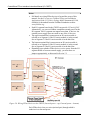
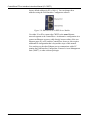
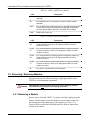
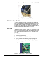
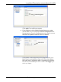
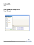
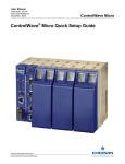
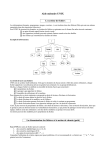
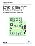
Instruction Manual Document: CI-CWFFI Part: D301634X012 November, 2009 FOUNDATION™ Fieldbus Interface Remote Automation Solutions www.EmersonProcess.com/Remote ControlWave IMPORTANT! READ INSTRUCTIONS BEFORE STARTING! Be sure that these instructions are carefully read and understood before any operation is attempted. Improper use of this device in some applications may result in damage or injury. The user is urged to keep this book filed in a convenient location for future reference. These instructions may not cover all details or variations in equipment or cover every possible situation to be met in connection with installation, operation or maintenance. Should problems arise that are not covered sufficiently in the text, the purchaser is advised to contact Emerson Process Management, Remote Automation Solutions division (RAS) for further information. EQUIPMENT APPLICATION WARNING The customer should note that a failure of this instrument or system, for whatever reason, may leave an operating process without protection. Depending upon the application, this could result in possible damage to property or injury to persons. It is suggested that the purchaser review the need for additional backup equipment or provide alternate means of protection such as alarm devices, output limiting, fail-safe valves, relief valves, emergency shutoffs, emergency switches, etc. If additional information is required, the purchaser is advised to contact RAS. RETURNED EQUIPMENT WARNING When returning any equipment to RAS for repairs or evaluation, please note the following: The party sending such materials is responsible to ensure that the materials returned to RAS are clean to safe levels, as such levels are defined and/or determined by applicable federal, state and/or local law regulations or codes. Such party agrees to indemnify RAS and save RAS harmless from any liability or damage which RAS may incur or suffer due to such party's failure to so act. ELECTRICAL GROUNDING Metal enclosures and exposed metal parts of electrical instruments must be grounded in accordance with OSHA rules and regulations pertaining to "Design Safety Standards for Electrical Systems," 29 CFR, Part 1910, Subpart S, dated: April 16, 1981 (OSHA rulings are in agreement with the National Electrical Code). The grounding requirement is also applicable to mechanical or pneumatic instruments that include electrically operated devices such as lights, switches, relays, alarms, or chart drives. EQUIPMENT DAMAGE FROM ELECTROSTATIC DISCHARGE VOLTAGE This product contains sensitive electronic components that can be damaged by exposure to an electrostatic discharge (ESD) voltage. Depending on the magnitude and duration of the ESD, this can result in erratic operation or complete failure of the equipment. Read supplemental document S14006 for proper care and handling of ESD-sensitive components. Remote Automation Solutions A Division of Emerson Process Management 1100 Buckingham Street, Watertown, CT 06795 Telephone (860) 945-2200 Emerson Process Management Training GET THE MOST FROM YOUR EMERSON INSTRUMENT OR SYSTEM Avoid Delays and problems in getting your system on-line Minimize installation, start-up and maintenance costs. Make the most effective use of our hardware and software. Know your system. As you know, a well-trained staff is essential to your operation. Emerson offers a full schedule of classes conducted by full-time, professional instructors. Classes are offered throughout the year at various locations. By participating in our training, your personnel can learn how to install, calibrate, configure, program and maintain your Emerson products and realize the full potential of your system. For information or to enroll in any class, go to http://www.EmersonProcess.com/Remote and click on “Training” or contact our training department in Watertown at (860) 945-2200. BLANK PAGE ControlWave FFbus Interface Instruction Manual (CI-CWFFI) Contents Chapter 1 – Introduction 1.1 1-1 Overview – What is the ControlWave FOUNDATION Fieldbus Interface?...................................1-1 Chapter 2 – Installing the Hardware 2.1 2.2 2.3 2.4 2.5 2.6 2.7 2.8 2-1 Remove the CWFFI from its Packaging....................................................................................2-2 If You Need to Set Jumpers, Remove H1 Carrier Modules from Slots.....................................2-2 Set Jumpers Based on Power Requirements (If needed) ........................................................2-3 Re-Insert Modules into Chassis Slots .......................................................................................2-5 Ground the CWFFI....................................................................................................................2-5 Connect Power to the CWFFI ...................................................................................................2-6 2.6.1 Using Power from an External Power Supply ...............................................................2-6 2.6.2 Using Power from a ControlWave MICRO....................................................................2-6 Wire FFbus Devices to the H1 Segment Board ........................................................................2-7 2.7.1 Using Internal Power.....................................................................................................2-9 2.7.2 Using External Power....................................................................................................2-9 Connect Ethernet Cables ..........................................................................................................2-9 Chapter 3 – Operation and Maintenance 3.1 3.2 Daily Operation..........................................................................................................................3-1 3.1.1 Status LEDs ..................................................................................................................3-1 Removing / Replacing Modules ................................................................................................3-2 3.2.1 Removing a Module ......................................................................................................3-2 3.2.2 Re-inserting a Module ...................................................................................................3-3 3.2.3 Fuse ..............................................................................................................................3-3 Chapter 4 – Troubleshooting 4.1 4.2 4.3 4.3 3-1 4-1 Guidelines .................................................................................................................................4-1 Powering Up..............................................................................................................................4-1 Hardware Procedures ...............................................................................................................4-2 4.3.1 Troubleshooting H1 Modules ........................................................................................4-2 Software Procedures.................................................................................................................4-2 Index Issued Nov-09 I-1 Contents v ControlWave FFbus Interface Instruction Manual (CI-CWFFI) vi Contents Issued Nov-09 ControlWave FFbus Interface Instruction Manual (CI-CWFFI) Chapter 1 – Introduction This manual describes how to configure the ControlWave FOUNDATION™ Fieldbus (FFbus) Interface hardware. Note: The ControlWave and ROC800 Foundation Fieldbus Interfaces contain open source software covered by the GPL and LGPL open source software licenses. The specific software being used is U-Boot, the Linux kernel, apt, and zziplib. These licenses are contained on the Field Interface Configurator Software CD (part numbers 395575-11-7 and FSFIC-1/FIC1). Source code is available upon request. You may obtain a copy of this source code by contacting Remote Automation Solutions Technical Support. Email your request to [email protected]. This manual does not discuss how to: Set up a FFbus network. (See the Fieldbus Foundation’s publication FOUNDATION Fieldbus Wiring and Installation Application Guide 31.25 kbit/s Voltage Mode, document AG-140, available for download from the Fieldbus Foundation website www.fieldbus.org.) Configure your ControlWave project to reference the ControlWave FFbus Interface. For information on that, see Appendix A of the Field Interface Configurator User Manual (Form A6250). Install and run the Field Interface Configurator software to configure the ControlWave FFbus Interface. For information on that, see the Field Interface Configurator User Manual (Form A6250). Configure FFbus devices. (See the manual accompanying the device.) Create or download a ControlWave project. (See Getting Started with ControlWave Designer D5085 and the ControlWave Designer Programmer’s Handbook D5125.) 1.1 Overview – What is the ControlWave FOUNDATION Fieldbus Interface? FOUNDATION Fieldbus (FFbus) consists of two separate bus networks. The first is the 31.25Kb “H1” bus for multi-drop connection to two-wire field devices. The second is the 10/100 Mbps Ethernet control network backbone with High Speed Ethernet (HSE) protocol for passing FFbus data. A wide range of FFbus measurement and control devices for the oil and gas, water, and wastewater industries is available. The ControlWave FOUNDATION Fieldbus Interface (CWFFI) is an addon component for the ControlWave that allows it to communicate with a network of FFbus devices. The CWFFI consists of a three-slot chassis. Slot 1 of the chassis holds an HSE server module that allows communication with a ControlWave controller, and, optionally a PC Issued Nov-09 Introduction 1-1 ControlWave FFbus Interface Instruction Manual (CI-CWFFI) running the Field Interface Configurator and Emerson’s Asset Management Suite (AMS®) or other software. The remaining slots hold one or two H1 carrier modules that allow communication with the FFbus devices. Figure 1-1. Typical FFbus Network Configuration The CWFFI operates with any ControlWave-series controller, communicating through a common IP network. Alternatively, you can set up a link using an Ethernet cross-over cable and port forwarding. For information on setting up port forwarding, see Section 3.3.4 of the Field Interface Configurator User Manual (A6250). 1-2 Introduction Issued Nov-09 ControlWave FFbus Interface Instruction Manual (CI-CWFFI) Chapter 2 – Installing the Hardware This chapter provides instructions on installing the ControlWave FFbus Interface (CWFFI) hardware. For software installation, see the Field Interface Configurator User Manual (Form A6250). In This Chapter 2.1 2.2 2.3 2.4 2.5 2.6 2.7 2.8 Remove the CWFFI from its Packaging ..........................................2-2 If You Need to Set Jumpers, Remove H1 Carrier Modules ............2-2 Set Jumpers Based on Power Requirements (If needed) ...............2-3 Re-Insert Modules into Chassis Slots ..............................................2-5 Ground the CWFFI ..........................................................................2-5 Connect Power to the CWFFI ..........................................................2-6 Wire FFbus Devices to the H1 Segment Board...............................2-7 Connect Ethernet Cables.................................................................2-9 As with all electrically powered devices, there is a risk of electric shock Warning if this unit is installed or used improperly, or subjected to environmental or physical conditions for which it was not designed. If you have any doubts regarding safe installation / operation, consult an electrician. To minimize danger of shock, proper grounding procedures must be followed. Please see supplemental document S1400CW for more information. Caution Warning This product contains sensitive electronic components that can be damaged by exposure to an electrostatic discharge (ESD) voltage. Depending on the magnitude and duration of the ESD, this can result in erratic operation or complete failure of the equipment. Read supplemental document S14006 for instructions on proper care and handling of ESD-sensitive components. Ensure that the area is non-hazardous before you make any communication connections (USB, RS-232, RS-485, Ethernet, etc.). You must complete several steps to set up the CWFFI: 1. Remove the CWFFI from its packaging. 2. If you need to set jumpers, remove H1 carrier modules from slots. 3. If required, set jumpers based on power requirements. 4. Re-insert modules into chassis slots. 5. Ground the CWFFI. 6. Connect power to the CWFFI. 7. Wire FFbus devices to the H1 segment board. 8. Connect Ethernet cables. Each step is discussed in its own section. Issued Nov-09 Installation 2-1 ControlWave FFbus Interface Instruction Manual (CI-CWFFI) 2.1 Remove the CWFFI from its Packaging The CWFFI ships from the factory already assembled. Remove it from its packaging. Figure 2-1. ControlWave FFbus Interface with HSE Server and one H1 Carrier Module Installed 2.2 If You Need to Set Jumpers, Remove H1 Carrier Modules from Slots The CWFFI chassis has slots for two H1 carrier modules (see Figure 21). Each H1 carrier module can handle two H1 segment boards, and has one optional internal power supply/conditioner per segment. Conditioned power is power which meets FFbus impedance specifications. Depending upon your implementation, you can either power FFbus devices using the H1 segment board or using an external power source. Jumpers on the H1 carrier module determine the choice of power source. 2-2 Installation Issued Nov-09 ControlWave FFbus Interface Instruction Manual (CI-CWFFI) Note: H1 carrier modules purchased with the optional power supply/conditioners ship from the factory with jumpers set to power FFbus devices from those power supply/conditioners. H1 carrier modules without these power supply/conditioners ship from the factory with jumpers set to use external power. If you know which configuration of the modules you purchased, and the default jumper settings satisfy your requirements, you can skip the rest of this section, as well as Sections 2.3 and 2.4. If, however, you are unsure which configuration of the module you have, or if you are unsure whether jumper settings have been changed since the unit left the factory, you must remove the H1 carrier modules as described in this section, and set jumpers according to instructions in the next section. You must exercise care when removing or replacing modules in the CWFFI to avoid damaging components. Caution Remove power from the CWFFI when removing or replacing modules. The CWFFI does not support hot-swapping of modules. To remove a module, tightly grasp the chassis with the palms of your hand, then use your fingers to press in the locking tabs on the short edges of the module (see Figure 2-2). Gently rock the module back and forth and lift it from its connections and out of the chassis. Figure 2-2. Plastic Locking Tabs on Modules 2.3 Set Jumpers Based on Power Requirements (If needed) Caution If you intend to use external power for your FFbus devices, you must set the appropriate power jumpers (W1 and/or W2) on the H1 carrier module to OFF. Any external power supply must meet FFbus power specifications. Issued Nov-09 Installation 2-3 ControlWave FFbus Interface Instruction Manual (CI-CWFFI) Figure 2-3 indicates jumper locations on the H1 carrier module. If the H1 carrier module includes the optional power supply/conditioners, the factory default setting for both W1 and W2 is ON. If the H1 carrier module does not include the optional power supply/conditioners, the default setting for jumpers W1 and W2 is OFF. Set the jumpers according to your power requirements: If you want the power supply/conditioner on the carrier module to power FFbus devices connected to segment 1, set W1 to ON. Otherwise, set it to OFF. If you want the power supply/conditioner on the carrier module to power FFbus devices connected to segment 2, set W2 to ON. Otherwise, set it to OFF. Figure 2-3. Jumper Locations on the H1 Carrier Module 2-4 Installation Issued Nov-09 ControlWave FFbus Interface Instruction Manual (CI-CWFFI) 2.4 Re-Insert Modules into Chassis Slots Once you’ve set the jumpers, you can re-insert the H1 carrier module(s) into the appropriate slots in the chassis. See Figure 2-1 to identify the chassis slots. Note: The HSE server module always resides in slot 1. You can install either one or two H1 carrier modules (H1) in slots 2 and 3. To insert a module, first make sure you have the correct slot, and that there are matching connectors on the backplane for this module. Grasp the module and align it with the chassis guides for its appropriate slot. Do not force the module. Gently push the module into the slot until the locking tabs snap into place (see Figure 2-2). 2.5 Ground the CWFFI The CWFFI chassis includes a ground lug on the bottom (Figure 2-4) that accommodates up to a #4 AWG wire size. We recommend you use stranded copper wire for your ground wire and keep the length as short as possible. Run the ground wire between the chassis ground lug and a known good earth ground. As an extra added precaution, we recommend you run a #14 AWG wire from the CWFFI power connector (chassis ground) to the same known good earth ground. Clamp or braze the ground wire to the ground bed conductor (typically a stranded copper AWG 0000 cable installed vertically or horizontally). Tin the wire ends (using a high wattage soldering iron) before you insert them into the chassis ground lug. Run the ground wire so that any bends in the cable have a minimum radius of 12 inches below ground and eight inches above ground. Figure 2-4. Ground Lug on Bottom of Chassis Issued Nov-09 Installation 2-5 ControlWave FFbus Interface Instruction Manual (CI-CWFFI) 2.6 Connect Power to the CWFFI The CWFFI has two power options: you can mount it as a standalone unit with an external power supply or it can receive power directly from a ControlWave MICRO. 2.6.1 Using Power from an External Power Supply In this case, you mount the CWFFI separately from the ControlWave, and you wire power to it from an external power supply. You can mount it in a panel or on a wall. A DIN rail mounting kit is also available. Connect power as shown in Figure 2-5. The CWFFI accepts a 24V nominal input (22-30V). Typical Configuration Bulk Supply #1 Pos. Term. Bulk Supply #1 Neg. Term. Chassis Ground + VIN - VIN CHASSIS Figure 2-5. Wiring the CWFFI to an External Power Supply The power connector uses compression-type terminals that accommodate up to #14 AWG wire. Insert the wire’s bared end (1/4” max) into the clamp adjacent to the screw and then secure the screw. Insert the wire fully making sure that no bare wire is exposed which could cause shorts. If using standard wire, tin the bare end with solder to prevent flattening and improve conductivity. Allow some slack in the wires when making terminal connections. The slack makes the connections more manageable and helps to minimize mechanical strain on the terminal blocks. 2.6.2 Using Power from a ControlWave MICRO Leave the three bus terminators from JP2, JP3 and JP4 of the ControlWave MICRO’s base backplane in place. (See Figure 1-5 and 16 of CI-ControlWave MICRO for the location of these jumpers on the ControlWave MICRO.) Mount the base housing on the left and the CWFFI on the right (see Figure 2-6), such that base housing power connector P10 (on right side of the base backplane) mates with power connector P7 (on left side of the CWFFI). 2-6 Installation Issued Nov-09 ControlWave FFbus Interface Instruction Manual (CI-CWFFI) Figure 2-6. ControlWave MICRO Connection to CWFFI (Front View) For a view from the rear and below showing the connectors, see Figure 2-7. Figure 2-7. Connecting the CWFFI to the ControlWave MICRO (view from behind and below) ) 2.7 Wire FFbus Devices to the H1 Segment Board Each H1 carrier module supports two H1 segment boards and each H1 segment board can have a maximum of 16 FFbus devices connected to it in parallel; this allows a maximum of 32 FFbus devices per H1 module. The actual number of devices you can include may be less than this amount based on multiple factors including wire length and the amount of current needed. Issued Nov-09 Installation 2-7 ControlWave FFbus Interface Instruction Manual (CI-CWFFI) Notes: Full details on wiring FFbus devices is beyond the scope of this manual. See the FOUNDATION Fieldbus Wiring and Installation Application Guide 31.25 kbit/s Voltage Mode, document AG-140, available for download from the Fieldbus Foundation website www.fieldbus.org. Each H1 segment board in the CWFFI can provide 125 mA @ 24V. Alternatively, you can use fieldbus-compliant external power for the H1 segment. No H1 segment can support more than 16 devices. An external power supply does not count as one of the 16 devices. The upper terminal block connector on an H1 carrier module is referred to as Segment 1 if the H1 carrier module is in the second slot or Segment 3 if the H1 carrier module is in the third slot. The bottom terminal block connector on an H1 carrier module is referred to as Segment 2 if the H1 carrier module is in the second slot or Segment 4 if the H1 carrier module is in the third slot. Depending upon whether FFbus devices receive power from the H1 segment board or from an external supply, you must have set jumpers appropriately, as discussed in Section 2.3. Figure 2-8. Wiring FFbus Devices to the CWFFI (Internal power – top, External power – bottom) Each FFbus device has two wires (twisted pair) through which it sends/receives data and power. 2-8 Installation Issued Nov-09 ControlWave FFbus Interface Instruction Manual (CI-CWFFI) To begin, you connect one wire from the FFbus device to one of the A terminals on the H1 segment board. Then you connect the other wire to one of the B terminals on the H1 segment board. Figure 2-8 shows this type of connection for FFbus devices #1, #4, and #5. You can connect additional FFbus devices in a chain using parallel connections. For example, in Figure 2-8, FFbus device #2 connects in parallel to FFbus device #1, and FFbus device #3 connects in parallel to FFbus device #2. Similarly, FFbus device #6 connects in parallel to FFbus device #5. The last device in any chain requires a terminator (shown by a “T”) in the figure. When wiring devices to the CWFFI, insert the wire’s bared end (1/4” max) into the clamp adjacent to the screw and then secure the screw. Insert the wire fully making sure that no bare wire is exposed which could cause shorts. If using standard wire, tin the bare end with solder to prevent flattening and improve conductivity. Allow some slack in the wires when making terminal connections. The slack makes the connections more manageable and helps to minimize mechanical strain on the terminal blocks. Optionally, you can wire PF+ and PF- as open collector outputs to report a power failure of the associated H1 segment board. 2.7.1 Using Internal Power If you want to power FFbus devices on a segment by the H1 segment board, you must connect jumper wires from CP+ to A on the terminal block, and CP- to B on the terminal block (see upper segment in Figure 2-8). CP refers to the conditioned power. Again, you must also set jumpers properly (see Section 2.3). 2.7.2 Using External Power If using external power, wire an FFbus-compliant power supply to the H1 segment board, as you would any FFbus device. (See lower segment in Figure 2-8.) FFbus devices #5 and #6 in the figure use the external supply. The power supply does not count towards the maximum device total for the segment. You must wire a terminator between the A and B terminals on the segment’s terminal block. In this case, do not connect jumper wires to the CP+ and CP- terminals since power comes from the external supply, not the H1 segment board. 2.8 Connect Ethernet Cables The HSE server module includes two Ethernet ports (E1 and E2 in Figure 2-9). The factory default address for E1 is 192.168.1.5; the Issued Nov-09 Installation 2-9 ControlWave FFbus Interface Instruction Manual (CI-CWFFI) factory default address for E2 is 10.0.0.1. You can change these addresses using the Field Interface Configurator software. Figure 2-9. Ethernet Ports on HSE Server Module Use either E1 or E2 to connect the CWFFI to the same Ethernet network segment as the ControlWave. An alternative configuration is to connect an Ethernet crossover cable directly between either of the two Ethernet ports (E1 or E2) and the ControlWave, however, this requires additional IP configuration that is beyond the scope of this manual. You can then use the other Ethernet port to communicate with a PC running the Field Interface Configurator, Emerson’s Asset Management Suite (AMS®), or other software packages. 2-10 Installation Issued Nov-09 ControlWave FFbus Interface Instruction Manual (CI-CWFFI) Chapter 3 – Operation and Maintenance This chapter discusses some basic service activities. As with all electrically powered devices, there is a risk of electric shock Warning if this unit is installed or used improperly, or subjected to environmental or physical conditions for which it was not designed. If you have any doubts regarding safe installation / operation, consult an electrician. To minimize danger of shock, proper grounding procedures must be followed. Please see supplemental document S1400CW for more information. Caution This product contains sensitive electronic components that can be damaged by exposure to an electrostatic discharge (ESD) voltage. Depending on the magnitude and duration of the ESD, this can result in erratic operation or complete failure of the equipment. Read supplemental document S14006 for instructions on proper care and handling of ESD-sensitive components. In This Chapter 3.1 3.2 Daily Operation ................................................................................3-1 3.1.1 Status LEDs..........................................................................3-1 Removing / Replacing Modules .......................................................3-2 3.2.1 Removing a Module .............................................................3-2 3.2.2 Re-inserting a Module ..........................................................3-3 3.2.3 Fuse......................................................................................3-3 3.1 Daily Operation Under normal conditions, the CWFFI operates automatically, along with its associated ControlWave host. Data transfers between FFbus devices and the H1 carrier module(s) in the CWFFI, and the CWFFI HSE server module sends data to the ControlWave through the Ethernet network. Optionally, the CWFFI also communicates with a PC running the Field Interface Configurator, AMS, or other software, through the other Ethernet port. If you change the control strategy running in the ControlWave host and the changes affect variables used in the application running in the CWFFI’s HSE server, you may need to modify and download a new application using the Field Interface Configurator. 3.1.1 Status LEDs The CWFFI includes a series of status LEDs to indicate proper system operation. See Table 3-1 for details on LEDs on the HSE server module, and Table 3-2 for details on LEDs on the H1 carrier module. Issued Nov-09 Operation and Maintenance 3-1 ControlWave FFbus Interface Instruction Manual (CI-CWFFI) Table 3-1. LEDs on HSE Server Module LED E1 Description If lit, Ethernet Port 1 is connected to an active network (carrier detected). E2 If lit, Ethernet Port 2 is connected to an active network (carrier detected). PWR If lit, the HSE server module has power. If the HSE server does not function but you believe it has power and this LED remains dark, you may need to replace the fuse on the HSE server module. USB Reserved for future use. Table 3-2. LEDs on H1 Carrier Module LED S1/S3 Rx Description If lit, communications are being received on Segment module 1 (if carrier module is in slot 2) or on Segment module 3 (if carrier module is in slot 3). S1/S3 Tx If lit, communications are being transmitted on Segment module 1 (if carrier module is in slot 2) or on Segment module 3 (if carrier module is in slot 3). S2/S4 Rx If lit, communications are being received on Segment module 2 (if carrier module is in slot 2) or on Segment module 4 (if carrier module is in slot 3). S2/S4 Tx If lit, communications are being transmitted on Segment module 2 (if carrier module is in slot 2) or on Segment module 4 (if carrier module is in slot 3). PF If lit, there is a power failure on this segment. 3.2 Removing / Replacing Modules You must exercise care when removing or replacing modules in the CWFFI to avoid damaging components. Caution Remove power from the CWFFI when removing or replacing modules. The CWFFI does not support hot-swapping of modules. 3.2.1 Removing a Module Remove power from the CWFFI. To remove a module, tightly grasp the chassis with the palms of your hands, then use your fingers to press in the locking tabs on the short edges of the module (see Figure 3-1). Gently rock the module back and forth and lift it from its connections and out of the chassis. 3-2 Operation and Maintenance Issued Nov-09 ControlWave FFbus Interface Instruction Manual (CI-CWFFI) Figure 3-1. Plastic Locking Tabs on Modules 3.2.2 Re-inserting a Module To insert a module, first make sure you have the correct slot and that there are matching connectors on the backplane for this module. Grasp the module and align it with the chassis guides for its appropriate slot. Do not force the module. Gently push the module into the slot until the locking tabs snap into place. Restore power to the CWFFI. 3.2.3 Fuse The HSE server module includes a 7x2 mm 1.5A slow blow fuse. If the HSE server module fails, and the PWR LED is off, but you know power is on, you may need to replace the fuse. Figure 3-2 shows the location of the fuse. To check the fuse: 1. Remove power from the unit. 2. Remove the HSE server module from the chassis. 3. With a digital multi-meter, check the resistance across the fuse. Normally the fuse has a resistance of less than 1 ohm. If the resistance shows “open line” on the multi-meter, the fuse has blown and you must replace it. Figure 3-2. Location of Fuse on HSE Server Module Issued Nov-09 Operation and Maintenance 3-3 ControlWave FFbus Interface Instruction Manual (CI-CWFFI) 3-4 Operation and Maintenance Issued Nov-09 ControlWave FFbus Interface Instruction Manual (CI-CWFFI) Chapter 4 – Troubleshooting This chapter provides generalized guidelines for troubleshooting the CWFFI and the H1 modules installed in it. Use the following tools for troubleshooting: A personal computer (PC) running Microsoft® Windows® 2000 (with Service Pack 2), Windows XP, or Windows Vista. Field Interface Configurator software (version 1.00 or newer). Flat-head (size 1/10 inch) and Philips (size 0) screwdrivers. In This Chapter 4.1 4.2 4.3 4.3 Guidelines ........................................................................................4-1 Powering Up ....................................................................................4-1 Hardware Procedures ......................................................................4-2 4.3.1 Troubleshooting H1 Modules ...............................................4-2 Software Procedures .......................................................................4-2 4.1 Guidelines When you are attempting to diagnose a problem with the CWFFI: Remember to write down what steps you have taken. Note the order in which you remove components. Note the orientation of the components before you alter or remove them. Read and follow all Cautions in this manual. 4.2 Powering Up If you are experiencing trouble with powering up the CWFFI: Check the wiring connections at terminations on the power input terminals and the wiring at the power source. Check the voltage. Check the external power source, if applicable, for voltage. Note: If none of these methods solves the problem, contact your local technical support representative. Issued Nov-09 Troubleshooting 4-1 ControlWave FFbus Interface Instruction Manual (CI-CWFFI) 4.3 Hardware Procedures Use the following procedure to resolve potential issues with the H1 modules. 4.3.1 Troubleshooting H1 Modules Verify the wiring for the H1 module (see Figure 2-8); note the relationship between the CP+ and CP– and A and B connections. Verify the wiring between the fieldbus devices and the H1 module. Power off and remove and reinsert the H1 module, then restore power (see Section 3.2). 4.3 Software Procedures With the Field Interface Configuration software running, you have several options to check the functioning of your modules: Right-click a segment and select Firmware Version from the popup menu. A message box displays: If the Configurator is not communicating with the segment, the following message box displays: In this case, follow the hardware troubleshooting procedure for the H1 module. 4-2 If you do not see the segment in the tree structure, right-click the HSE server icon and select General Configuration from the popup menu. From the Configuration screen, click the HSE Server icon and verify on the HSE Server tab that all segments have been enabled: Troubleshooting Issued Nov-09 ControlWave FFbus Interface Instruction Manual (CI-CWFFI) Enabled segments Click Apply if you enable any segments. If you do not see a device displayed on the directory tree, rightclick the HSE server icon and select General Configuration from the pop-up menu. From the Configuration screen, open the segment and select the segment to which the device is attached: Node values Verify that the value assigned to the First Unpooled Node is not higher than the actual number of that node. If the value is higher, the system may be skipping the node as it routinely polls. Increase the value to accommodate your device’s node. Click Apply if you make any changes. Issued Nov-09 Troubleshooting 4-3 ControlWave FFbus Interface Instruction Manual (CI-CWFFI) 4-4 Troubleshooting Issued Nov-09 WARRANTY A. Remote Automation Solutions (RAS) warrants that goods described herein and manufactured by RAS are free from defects in material and workmanship for one year from the date of shipment unless otherwise agreed to by RAS in writing. B. RAS warrants that goods repaired by it pursuant to the warranty are free from defects in material and workmanship for a period to the end of the original warranty or ninety (90) days from the date of delivery of repaired goods, whichever is longer. C. Warranties on goods sold by, but not manufactured by RAS are expressly limited to the terms of the warranties given by the manufacturer of such goods. D. All warranties are terminated in the event that the goods or systems or any part thereof are (i) misused, abused or otherwise damaged, (ii) repaired, altered or modified without RAS consent, (iii) not installed, maintained and operated in strict compliance with instructions furnished by RAS or (iv) worn, injured or damaged from abnormal or abusive use in service time. E. These warranties are expressly in lieu of all other warranties express or implied (including without limitation warranties as to merchantability and fitness for a particular purpose), and no warranties, express or implied, nor any representations, promises, or statements have been made by RAS unless endorsed herein in writing. Further, there are no warranties which extend beyond the description of the face hereof. F. No agent of RAS is authorized to assume any liability for it or to make any written or oral warranties beyond those set forth herein. REMEDIES A. Buyer's sole remedy for breach of any warranty is limited exclusively to repair or replacement without cost to Buyer of any goods or parts found by Seller to be defective if Buyer notifies RAS in writing of the alleged defect within ten (10) days of discovery of the alleged defect and within the warranty period stated above, and if the Buyer returns such goods to the RAS Watertown office, unless the RAS Watertown office designates a different location, transportation prepaid, within thirty (30) days of the sending of such notification and which upon examination by RAS proves to be defective in material and workmanship. RAS is not responsible for any costs of removal, dismantling or reinstallation of allegedly defective or defective goods. If a Buyer does not wish to ship the product back to RAS, the Buyer can arrange to have a RAS service person come to the site. The Service person's transportation time and expenses will be for the account of the Buyer. However, labor for warranty work during normal working hours is not chargeable. B. Under no circumstances will RAS be liable for incidental or consequential damages resulting from breach of any agreement relating to items included in this quotation from use of the information herein or from the purchase or use by Buyer, its employees or other parties of goods sold under said agreement. How to return material for Repair or Exchange Before a product can be returned to Remote Automation Solutions (RAS) for repair, upgrade, exchange, or to verify proper operation, Form (GBU 13.01) must be completed in order to obtain a RA (Return Authorization) number and thus ensure an optimal lead time. Completing the form is very important since the information permits the RAS Watertown Repair Dept. to effectively and efficiently process the repair order. You can easily obtain a RA number by: A. FAX Completing the form (GBU 13.01) and faxing it to (860) 945-2220. A RAS Repair Dept. representative will return the call (or other requested method) with a RA number. B. E-MAIL Accessing the form (GBU 13.01) via the RAS Web site (www.emersonprocess.com/remote) and sending it via E-Mail to [email protected] . A RAS Repair Dept. representative will return E-Mail (or other requested method) with a RA number. C. Mail Mail the form (GBU 13.01) to Remote Automation Solutions A Division of Emerson Process Management Repair Dept. 1100 Buckingham Street Watertown, CT 06795 A RAS Repair Dept. representative will return call (or other requested method) with a RA number. D. Phone Calling the RAS Repair Department at (860) 945-2442. A RAS Repair Department representative will record a RA number on the form and complete Part I, send the form to the Customer via fax (or other requested method) for Customer completion of Parts II & III. A copy of the completed Repair Authorization Form with issued RA number should be included with the product being returned. This will allow us to quickly track, repair, and return your product to you. Remote Automation Solutions Repair Authorization Form (Providing this information will permit Remote Automation Solutions to effectively and efficiently process your return. Completion is required to receive optimal lead time. Lack of information may result in increased lead times.) Date ____________ RA # _________________ Standard Repair Practice is as follows: Variations to this is practice may be requested in the “Special Requests” section. • Evaluate / Test / Verify Discrepancy/Repair/Replace SH Line No. _________ Please be aware of the Non warranty standard charge: • There is a $100 minimum evaluation charge. The party sending in material is responsible to ensure that the materials returned are clean to safe levels, defined and/or determined by applicable federal, state and /or local law regulations or codes. Such party agrees to indemnify Remote Automation Solutions harmless to any liability or damage which Remote Automation Solutions may incur or suffer due to such party’s failure to so act. Part I Please complete the following information for single unit or multiple unit returns Address No. _____________ Address No. ____________ Bill to : _____________________________________ Ship to: ___________________________________ ____________________________________________ ____________________________________________ ____________________________________________ ____________________________________________ Purchase Order: _________________________ Contact Name: _____________________________ Phone: _____________________ Part II Fax: ______________________ E-Mail: ______________________ Please complete Parts II & III for each unit returned Model No./Part No. _________________________ Description: __________________________________ Range/Calibration: _________________________ S/N: ___________________________________ Reason for return : Failure Upgrade Verify Operation Other __________________________ 1. Describe the conditions of the failure (Frequency/Intermittent, Physical Damage, Environmental Conditions, Communication, CPU watchdog, etc.) ___________________ (Attach a separate sheet if necessary) 2. Comm. interface used: Standalone RS-485 Ethernet Other: ______________________________________ Modem (PLM (2W or 4W) or SNW) 3. What is the Firmware revision?_______________ What is the Software & version? _______________ Part III If checking “replaced” for any question below, check an alternate option if replacement is not available A. If product is deemed not repairable would you like your product: returned replaced B. If Remote Automation Solutions is unable to verify the discrepancy, would you like the product: replaced scrapped? returned *see below? * Continue investigating by contacting the customer to learn more about the problem experienced? The person to contact that has the most knowledge of the problem is: __________________ phone _________________ If we are unable to contact this person the backup person is:________________ phone _________________ Special Requests: __________________________________________________________________________________________ Ship prepaid to: Form GBU 13.01 Remote Automation Solutions, Repair Dept., 1100 Buckingham Street, Watertown, CT 06795 Phone: 860-945-2442 Fax: 860-945-2220 Rev. F 11/25/08 BLANK PAGE Index C H Conditioned power defined............................................................ 2-2 H1 carrier board setting jumpers on the ............................. 2-2, 2-3 HSE Server module Ethernet ports on the .................................... 2-10 fuse ................................................................. 3-3 E Ethernet Ports on HSE Server module................................. 2-10 F FFbus devices wiring to the H1 segment board ..................... 2-7 Figures 1-1. Typical FFbus Network Configuration..... 1-2 2-1. ControlWave FFbus Interface with HSE Server and one H1 Carrier Board Installed.. 2-2 2-2. Plastic Locking Tabs on Boards.............. 2-3 2-3. Jumper Locations on the H1 Carrier Board ...................................................................... 2-4 2-4. Ground Lug on Bottom of Chassis.......... 2-5 2-5. Wiring the CWFFI to an External Power Supply .......................................................... 2-6 2-6. ControlWave MICRO Connection to CWFFI ...................................................................... 2-7 2-7. Connecting the CWFFI to the ControlWave MICRO ......................................................... 2-7 2-8. Wiring FFbus Devices to the CWFFI ...... 2-8 2-9. Ethernet Ports on HSE Server Board ... 2-10 3-1. Plastic Locking Tabs on Modules ........... 3-3 3-2. Location of Fuse on HSE Server Modules 33 FOUNDATION Fieldbus Overview......................................................... 1-1 Fuse on HSE Server module................................... 3-3 G Grounding ........................................................... 2-5 L LEDs descriptions of ................................................ 3-1 Licenses Open Source Software ................................... 1-1 M Modules removing/replacing ......................................... 3-2 O Open Source Software........................................ 1-1 P Power connecting ...................................................... 2-6 jumpers to choose external or internal ........... 2-2 powering FFbus devices from external supply2-9 powering FFbus devices from H1 segment module.......................................................... 2-9 S Status LEDs ........................................................ 3-1 T Tables 3-1. LEDs on HSE Server Module.................. 3-2 3-2. LEDs on H1 Carrier Module .................... 3-2 Troubleshooting .................................................. 4-1 ControlWave FFbus Interface Customer Instruction Manual CI-CWFFI November, 2009 NOTICE Emerson Process Management Remote Automation Solutions 1100 Buckingham Street Watertown, CT 06795 Phone: +1 (860) 945-2262 Fax: +1 (860) 945-2525 www.EmersonProcess.com/Remote Emerson Process Management Remote Automation Solutions 6338 Viscount Rd. Mississauga, Ont. L4V 1H3 Canada Phone: 905-362-0880 Fax: 905-362-0882 www.EmersonProcess.com/Remote Emerson Process Management SA de CV Calle 10 #145 Col. San Pedro de los Pinos 01180 Mexico, D.F. Mexico T +52 (55) 5809-5300 F +52 (55) 2614-8663 www.EmersonProcess.com/Remote Emerson Process Management, Ltd. Remote Automation Solutions Blackpole Road Worcester, WR3 8YB United Kingdom Phone: +44 1905 856950 Fax: +44 1905 856969 www.EmersonProcess.com/Remote Emerson Process Management AP Pte Ltd. Remote Automation Solutions Division 1 Pandan Crescent Singapore 128461 Phone: +65-6770-8584 Fax: +65-6891-7841 www.EmersonProcess.com/Remote “Remote Automation Solutions (“RAS”), division of Emerson Process Management shall not be liable for technical or editorial errors in this manual or omissions from this manual. RAS MAKES NO WARRANTIES, EXPRESSED OR IMPLIED, INCLUDING THE IMPLIED WARRANTIES OF MERCHANTABILITY AND FITNESS FOR A PARTICULAR PURPOSE WITH RESPECT TO THIS MANUAL AND, IN NO EVENT SHALL RAS BE LIABLE FOR ANY INCIDENTAL, PUNITIVE, SPECIAL OR CONSEQUENTIAL DAMAGES INCLUDING, BUT NOT LIMITED TO, LOSS OF PRODUCTION, LOSS OF PROFITS, LOSS OF REVENUE OR USE AND COSTS INCURRED INCLUDING WITHOUT LIMITATION FOR CAPITAL, FUEL AND POWER, AND CLAIMS OF THIRD PARTIES. Bristol, Inc., Bristol Babcock Ltd, Bristol Canada, BBI SA de CV and the Flow Computer Division are wholly owned subsidiaries of Emerson Electric Co. doing business as Remote Automation Solutions (“RAS”), a division of Emerson Process Management. FloBoss, ROCLINK, Bristol, Bristol Babcock, ControlWave, TeleFlow and Helicoid are trademarks of RAS. AMS, PlantWeb and the PlantWeb logo are marks of Emerson Electric Co. The Emerson logo is a trademark and service mark of the Emerson Electric Co. All other trademarks are property of their respective owners. The contents of this publication are presented for informational purposes only. While every effort has been made to ensure informational accuracy, they are not to be construed as warranties or guarantees, express or implied, regarding the products or services described herein or their use or applicability. RAS reserves the right to modify or improve the designs or specifications of such products at any time without notice. All sales are governed by RAS’ terms and conditions which are available upon request. © 2009 Remote Automation Solutions, division of Emerson Process Management. All rights reserved.