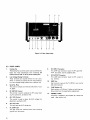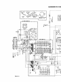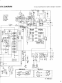
1
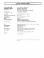
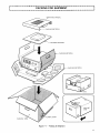
,
'8
T
c
L
I
K
g
N
t
/
E
p
1
R
2
S
A
W
O
D
o
M
J
P
U
.
C
L
l
F
B
R
5
E
T
2
8
O
4
A
o
(
K
N
)
G
M
U
A
L
I
I
I
I
g
AFTER uNpAcKING
Itjsadvisableto savealIoriginalpackingcartons(innerand
outer) to protect your valuable Linear Am plifier from
damage should you wish to transportitforremote opera-
CA UTlO N
Read Operating ManualSection 2 before proceeding to
unpackand assem bleyouram pIifier.
w A RN ING
tion orship it for after-sales service.
The foIlowing explicit definitions apply in this m anual.Be
LETHA L VOlTAGES PRESENT.
s
uretor
eadthes
edefi
ni
ti
ons.
NOTE =
1
,
,
,
!
,
!
,
,
l
If disregarded, inconvenience onl
y - no
t
daMage orperSOnalinjUry.
j
CAUTlON = equipm ent damage m ay occur, but not
personalinjury.
WARNING m personal injury may occur - do not dis-
l
regard.
3t
I
q
3
4
y
CoNTENTS
rL.g22A spEclFlcATIoNs ...................3
Ecrlo N 1 FEAruREs ...................4
sEcr o N 2 pREpA RArloN fOR USf .........5
2.1 Accessor;es
2,2 lnstallation of Power Tubes
2.3 ceneralTips on lnstallation
2.q AC pow er Source
2.5 Line Voltage Change
2.6 pow er Cable
2.7 Excìter
2.8 Antenna
2.9 Interconnection
2.g.1 cround;ng
2.9.2 Cable Connection
sEcrloN 3 CoNrRo Ls AND THElR FUNCTlONS .9
3.1 Front panel
3.2 Rear Panel
sEcTIoN 4 opERArlo N ........,......... 11
q.1 prechecks
q.2 CW Operation
q.3 SSB operat;on
q,q RTTY Operation
-q.5 Sett;ng the A LC ADJ ControI
q.6 Ad;usting the Rf OutputMeter
q.7 H igh-Voltage Transform er Protection
.8 Carrying Your TL-922A
sEcrloN 5 c Rculr 0 EsCR prlo N ...........13
5.1 Linear pow er Am plifjer
5.2 Power Supply
5.3 Fan M otor DeIay Stop Circuit
5.Q Meter Drive Circuit
5.5 Spark Suppressor
2
SECTlON 6 MA INTENA NCE .........,...... 15
6.1 InternalCleaning
6.2 Replacing Pow er Fuses
6.3 Replacing Pow er Tubes
6,4 lnpUt MatChin9 CirCUit
SECTlON 7 TROU BlESHOOTIN G HlNTS .,,... 16
PA CKIN G ................................ 17
lNTERNA L PA RT LOCATlO NS ..,.,,.,.,.,,,, 18
SCH EM ATIC D IA GRAM ..................., 19
IlLU ST RATIO N S
Fig. 2- 1 UpperCase CoverAssembl
y/
Disassembl
y ,....................
Fig.2-2 Correct Pow er Tube Handling ........
Fig.2-3 Parasìtic Suppressor CoilM ounting ....
Fig.2-4 lnput Voltage Term inal Boards .......
fig.2-5 Power Cable Color Code ............
Fig.2-6 Exciter Connections for R L and A LC
5
5
6
7
8
Controls ........................ 8
Fig.2-7 Interconnection of the TL-922A ...... 8
Fig.3-1 Front View ...................... 9
Fig.3-2 Rear View ...................... 1O
Fig.5-1 Linear PowerAmplifierCircui
t ....... 13
Fig.5-2 Transformer PriMarY Current Flow ..... 14
Fi9.5m3 Fan M OtOr DelaY StOp CirCUi
t ........ 14
Fig.5-4 M eter Drive Circuit ................ 14
Fi9.7-1 PaCkín9 fOr Shipment .............. 17
Fi9. 7-2,3TOp,BOttOm View S ...,,.,......... 18
rA BLEs
1. frOnt Panel COntrOIS Set-Up .............. 11
2 TUne and LOad Ini
tialSe in9S
11
r
'
,
JlJJJI lJJJI JJJlI.JIJlI llllI-JJllI llIlI.lllJIlJJJJI.IllJI llJJIIllllI lIJlI.IlJlJI"JJlJI.IJJJJI.lJJlJI.IJJJJI"IJJJJI"JJJJI-JJJJIIJlJJI- JJJJI.IJJlJIIllJJIIJJJJI-IJJJJI-IJlJJI"IJlJJIJllJJI"JJJJI-JJJJI- I"IJJJJI JJJlI-llJlI
'
-
,
_
_
_
__
lJllI llJJI.llJJI.JJllI llllI JlIlI llll
I.lJllI.IJJllI-IJJJJI_"
TL-922A S pEC IFICA TIO S
IlIlI IlllI IlllI llllIIlJllI"IlJJJI- m -JJJJI-m JI.JJJJI.IlJJJI.lJJJI.IJJII JlllI lJJl- I- I-
-It
=
,
__
_
__
IlJJJI lJJlI- I lllII IllJI-IJlJJI"IlJlII lllJI- JlI"IlllJI lJlII lIllI-tllJJIIlJJJIi
Transm it Frequency Range"
.
160 m through 15m A m ateur Bands
Excitation Energy Required"
.
Mode and Duty Cycle.
80 W nom inal, 120 W m axim um
SSB,continuous for 30 m inutes.
CW and RTTY ,key own continuousfor 1O m inutes.
Rated Plate lnput.
2 kW P.E.P.SSB,1 kW CW RTTY
Plate Voltage"
.(athlo signal)
3.1 kV SSB,2.2 kV CW RTTY
Circuit Type:
CIass A B2 grounded grid linear am plifier
3rd Order Jnterm oduIation D istortion;
lnput lm pedance"
.
Below -30dB.
50 n ,unbalanced at better than 1.5 SW R
Output lm pedance.
50 to 75 n ,unbalanced.
Cooling"
.
lnterlock Satety Features;
Therm alProtector;
Forced A ir.
Prim ary high voltage circuit cut-off.
Secondary high-voltage circuit grounding.
Locks out transm it relays if H .V.pow er transform er overheats.
fan MotorDelay Stop Tim e;
140 +
- 30 seconds. (atroom temperature)
A LC;
Negative going,adjustablethreshoId -8V C maxim um output (typical).
power Tubes U sed.
Q m iconductors:
Eim ac 3-500Z ,tw o pieces
iodes, 18 pieces
'
_
lener diode, 1 piece
powerRequ;rem ents.
Cablegsuppl;ed.
120V,28A ;240V,1qA ;50/60H ;form axim um SSB input.
Si
gnalcable (coaxial)with U H F-type connector,1.5m.
Controlcable, 1.5m .
Dimensions;
Weight.
390m m x 19O mm X 407m m (15-3/8 X 7-1/2X 16')
Net3tkg (68 Ibs.)
Shipping 38 kg (83 Ibs.)
The above specifi
cations are subjectto change w i
thoutnotice dueto technicalim provem ent.
f
=
-
lIllllllIll.llllll.llllIlillIlllIlIll.llllll.llIlllllIlIl.llIlll.lIllIl.llllIllllIllllllIl.lIllll.llllIIllIllllIlllIlHHllllIll.llllllIlIlJl.lIlllI.lHllllHHIIJllIIlIlIlIlHHIlIlllIlIlllIIIlIllllllllllllIllmIllllHllllllllIlIllllIllllllIllllllIl_
s EC T IO N 1. FEA T U R ES
.
.
_
_
__
,
=
-,
-
_
_
_
_
íilJllt,llJlll.lJJlllllllJlllJIllllllll.l llllIllIm Jl.l ll.I -IlIlIliHIJl.lIJJJllIlIll-l l-l -l IlllIlIIIlIlI llllllllllll.lIlllllIlIll.llllIl.llIlll.lllIlllIlIJIlIllllllIlIlllllllllllllillIlllllIll-I lllIllllHHIllllll-llIJJl.llIlll_i
1.
The T L-922A is a Class AB2, grounded grid linear
am plifier developed by Trio-Kenwood through advanced high-power technology using tw o high-performance Eim ac 3-500l power tubes. lt covers all
bands 160 m through 15 m for SSB,CW and R TTY
linearity,and the CW Mode for low powerconsum ption and heat generation during extended periods of
operation.
8.
m odes of operation.
2.
3.
This switch iscapable of setting yourT L-922A in the
straight-through state irrespective of the standby
control on the exciter.
Unprecedented Reliabjli
The T L-922A isdesigned to provide stable,high RF
oUtputpowerrorextended per;odsorcont;nuoususe.
Eng;neered w;th Tr;o_Kenwood,sadvanced c;rcu;tand
caItechnoIogy, the T L_922A empIoys two
m echan;
d
3_
5ooz powertubesto the;rruIIadvantage.
rugge
linearAmpIification ControlSw itch
9.
'
,
,
:
'
'
'
!
!
,
VariabIe Threshold Level (A LC Detector)
,
The A LC circuit wiIlaccomm odate exciterS of 80 w
,
to 120 w (nom inal)by varying the A LC threShold
Ievel. This effectively prevents overdriving the final
powertubes, ;m ;t;ng the Am pI;f:erto :ts l:near range
and gUaranteein9 lOW diStOrtiOn atM aXim UM POWef
low ntermod,lat;on D ;stort;on
,
'
'
.
i
,
Intermodulation distortion (lM D) is m inim ied
through the useofnegative R.f.feedback.
q.
1O. Two PanelM etert
ln adjusting ormonitoring yourTL-922A,one meter
aIwaysindicatesthe (lp)platecurrent;while,with'the
other,you may read (Ig)grid current,(RF)relative
output,or(HV)high vol
tage. Thisfacili
tatesease of
Qu;c Turn.on
W arm-up isnot necessary.The 3.500Z tubesarefast
heatjng.
operation of your TL-922A.
5.
6.
FullSafety System
To protectyou against any possible high voltage electr;c shock,yourT L-922A has a double safety system
11. Rigid MechanicalStructure
Thedie-cast side panelseffectiveIy supportthe weight
comprised of interlocking switches. One interrupts
of the am plifier against shocks and jarring during
the high voI
tage primary circuit w hile the second
directly grounds the secondary high voltage circuit.
Also provi
ded are bleederresistorsfordischarging the
high voltage capacitors and ''DA NG ER''warnings at
high voltage positions. Please observe all warnings,
they are for your protection.
transportation. Recessed side panelhandles are provided so the Am pIi
fiercan be easil
y carried.
is rem oved from the un;t and w iII measurably extended tube life.
.
7.
Mode Switch forEffic;ent LinearOperation
M O D f switching js provided to select between the
SSB Mode for the maxim um PEP outputw ith good
1
!
!
,
,
!
'
,'
I
,
!
i
i
,
t
.
,
,
,
'
,
12. Vernier Plate Tuning 0ial
The PLAT E tune dial is equipped with a reduction
gear that facilitates easy tuning, particularly for the
:
,
.
'
,
higher bands. lt also effectively preventsaccidental
'
í
m iss-tuning during operation. Controls and panel
arrangement, designed to hum an engineering
standards, provide superior ease of operation.
'
,
.
hlewly-0eveIoped fan Motor0elay Stop Circuit
To reduce power tube deterioration, yourT L-922A
has a newly-developed fan m otor delay-stop circuit
com prised of a thermaldelay relay.The cooling fan
wiIInormally run for1QO seconds (Typ)afterpower
i
,
,
,
!
7
13.
eat,Contem porary Appearance
M echanjcalarrangementand sophisticated design tO
m atch any Trio-Kenw ood tranSCeiver OrtranSm itter.
Your TL-922A can aIso be used as a high-quality,
general purpose Amateur band Iinear am pIifier W ith
any exciter capable of 80W to 12OW Rf OUtpUt,
)
(
j
,
;
,
'
i
.
,
4
'
?
_
,
2
.
t
r
e
c
f
k
3
4
U
'
A
l
.
,
y
C
h
J
X
a
(
i
T
n
F
t
O
q
o
s
U
S
'
f
2
r
.
,
9
p
0
1
4
a
C
c
l
O
s
t
_
'
k
i
5
S
f
o
R
2
.
n
u
b
e
y
,
I
X
p
M
1
r
0
4
'
U
W
T
a
i
s
3
/
)
.
o
_
d
5
8
g
7
,
m
1
P
2
'
I
L
w
i
O
S
n
s
H
9
.
t
E
h
o
l
$
u
1
"
,
3
C
A
g
2
;
e
U
O
5
'
s
T
H
)
L
8
f
.
7
i
o
?
I
1
n
,
t
9
e
2
Y
!
a
p
3
H
s
r
N
'
w
.
4
A
,
n
m
g
o
!
p
'
a
I
c
.
l
,
i
e
t
1
s
C
p
'
o
R
O
!
r
.
D
n
,
c
e
y
E
d
s
'
p
!
.
A
,
R
'
!
4
6
5
.
c
p
L
N
T
A
E
,
s
r
'
I
o
a
0
C
h
n
R
!
l
c
F
e
N
d
.
k
t
m
T
,
G
u
f
v
i
o
'
p
E
P
n
s
h
D
I
R
e
g
F
y
L
!
.
r
t
,
l
b
u
i
a
d
'
R
s
n
e
P
!
h
H
t
,
c
x
.
r
o
y
1
l
p
M
u
^
'
A
e
i
v
S
,
R
J
t
f
a
h
.
Y
E
o
!
n
L
l
u
P
d
s
e
'
A
i
,
"
r
t
O
h
f
.
c
x
T
E
a
m
s
'
e
C
b
,
(
H
i
y
R
l
v
!
.
t
O
\
u
'
N
h
f
e
o
s
r
,
g
.
i
c
D
n
l
a
'
!
E
t
F
p
e
,
.
A
4
s
c
u
1
n
'
m
o
v
R
2
E
l
)
w
.
k
p
,
'
e
s
I
n
t
_
5. spareruse,15AFo5-1533-o5
2p;eces
6. Extensjon footJ02-OOQ9.14
.
2 pieces
7. Scr$ws,4 x 12m m long N30-QO12-46
8. Platg cap F02-0407-04
g. paras;t;csuppr$ssor ;I,,;ghih,nd
L3g-o4o1-o5
1O. Parasiticsuppressorcoil,lefthand
2 pieces
2 pieces
1 p;ece
1 piece
l
.
q P!eces
'
eces
Q pi
v,
.b,ai,
.o, ,,d h , d .
.
e
a
r
a
S P t0lY frO
procedu res below. Prepare
pl't' CaP
par,s;t;, suppresso,co;' ,;ghth,,d
,,d Iefih,,d
re^,3 x 6 mm long
Ptain washer
Spring ^asher
Tools
.
-
Ph
S
illilpstss
crewd
v
eewdr
r iver
mal
andar
dr
si
cr
-' '
1
?
P !
,
x\x\
.
2 P,eces
)
Sw,TcH
PLUNGER
4 pieces
4 pieces
Q pieces
!,
NOTE. A parts tray to prevent loss of m etri
c hardware is
i
hetprul.
WARNlNr
G
h
.
g
p
B
o
e
w
t
o
0
r
e
c
$
p
b
r
o
l
0
c
e
;
e
s
d
N
i
n
o
g
T
,
m
p
a
l
u
k
g
e
g
s
0
u
d
r
e
;
n
t
h
t
a
h
t
0
.
w
8
l
l
o
u
t
l$t.Th0METERswitchis$tth0HVposition
8nd th0 m ultím $t$r r0$ds OV.
Proceed as follow s. (Referto Fig.2-1)
2.
Remove the four 4 m m Phillips scre^s holding the
upper case cover.
Removethe uppercasecover.
.
.P' SCr'^S
R'MOV' !h' tOUr 3 ? M S'l!-"PP'n9 ph.
'iI!
and fOU, fl,t head Self-t,ppin9 PhillipSSCrew ShOldin9
the insideshield on the powertube enclosure.
,
''
-;
,
,,
/,,
\? ,, '
!
,','.!
!
!
'
'
,
'
1
!
'
'
-
/ i ///
/
//
/ //-
i/ /
Figur02-1
UPP0r C8s0 Cov0r
Assgmbly/Disgss0mbly.
1 p;ece e,,h
1
ie
ce
lp
pi
ece
..
,,,. '
/'
E )
m
._
!
t
\ ,
/,
! n
^? ''' 'tTT''/!
pí
"' -/
/ i !/1//
/?<?XXm ? '
USE #2 Phillips
Scr$w driv$r.
\ \
h
?
,
1.
\ ii'
UPPER C A S
co v E R
,NSERT
SH lELO
!
'
,'
2 p;eces
,
,
!i
\ \"\?
the following mounting
hardware and iools.
Mou,t,,g H,,dw,,e
powe,tube,3.5ooz
!
.
1
ìl
O
ie,U
mni
0
,,
.
.
et
,
''nS
,
h''
'k
fP
OO
'i
nSt
e
tY
iOnW
,'
fr
O'
llOP
Wa
t'
hd
'
,
0
b
''
\
-
g l - '
-', t
l
I
J
NsTA LLAT oN o F pow ER TuBEs
2'2 p,I
oig,t thg power iubes ,, your TL g22A ag,,,si
, ,scREws
\
'
'ì'
sw,TcH I
PLUN,ER
j
qp;
e,es
?
3m m SE LFA pp,N ,
^\\.\'\
3,m F ,A, H EA
sELF-TApp N, \ '
scREw (4 pcs) '
H,,H ,o Ll
TA,,
sEcoNoARy
'
pROTECTlON
L3g-o4o2-o5
11' SC!0w ' 3 X 6M ? I0?9 N3o- 3oo6- q6
12. Plain w asherN 15- 1030-46
q6
13' spr,,gwashe,N16. 3o-
io
,,S
i ITCHPLUNGER
''
I'
1.i,
,
i.
,,
,
,
\)
!
i
'
!
1
i
'
,
i
1
i
I
!
,
',
i
!
'
,
,
??
h
'
'
--_
'.
'
_ -
Figur0 2-2 - 0 rre Po
ru Handl;n
CAUTIO N
Tubelnstallation Checkout
part;cular care should be taken not to strike and
break the glass tubes during installation.Tube break-
.
1.
age due to negligence isnot w arrant
a.
Fi
TeMp
Oraril
y;tht
fiXhe,
eaCett
h par
it
iCSUp(Referrtoco;
,g.
on2t3)
he pi
ate capw
er,aS
,R,
,or,
,L,,
b
adjusted.
mount ,,e p,a,e cap w;th paras;t;csuppressorcoiton
ach ,ube observ;ng the r;ght hand and ,erthand co:,
e
2
d
Power tubes are free frOM SCratCheS or Othef
physicaldefects
iUb''ar' rUI,Y .
'
.r'O'k'''
'?S'r''d.
'n'O ',''
C
Plate CaP SCreW St'
l9htened SeCUfeIYt
d
Scre,s at both endsof the parasitic suppressor
'
.,Sare ,'
.9htened SeCUreIY'
CO,
w
.
'
"','r','Cr'w',df'V'r' 'n 'nY O'h'rU'n''''S'rY Ma''f'''iS nO'''!' i?Sid''h' U?i'
Referto Fig 2-1 The inside shi
eld pl
ate includesthe
preSSOup Att,,st,, e do nott,g,te,,,e q , , s,rew
.
aC,,g '
'
,
.,
b
and Sprin9 W aSher,bUt SnU9 theM SO t e COl M aY e
8.
To avoid daM age neCeSSitating tUbe reptaCeMent,
pleaSe CheCk;
i
!
,
t
p
h
e
r
e
s
i
c
g
C
i
n
s
o
e
a
i
t
I
i
n
o
b
s
n
y
t
s
a
'
S
la
l
i
f
9
t
h
i
th
o
ne
be
,
k
s
'
c
e
d
ri
e
p
w
n
i
9
ng
h
O
o
r
t
I
h
eS
Xt
d
C
e
o
ni
d
l
n
i
D
b
Oe
9
tI
O
b
a
W
y
l
i
9h
n
t
h
a
,
e
n
S
d
h
t
e
a
f
V
p
O
er
l 's
he
b
i
a
g
c
k
h
er
u
l
v
i
e
t
o
e
l
y
l
t
b
an
e
g
r
e
'
g
)
a
P
s
g
e
oc
s
'
o
i
t
h
n
i
o
e
dn
a
s
r
t
p
y
h
r
e
i
pg
n
p
r
o
l
a
t
p
e
t
l
e
ct
a
s
e
i
on
f
t
o
hr
s
at
w
un
t
i
h
g
c
e
r
h
o
p
u
p
I
u
n
l
u
ng
d
n
i
n
gr
e
ew
r
th
(
i
a
e
,
l ,
of the pIate cap.
cAuTloN.
. pait;cular care shouId beexerc:sed Jn not
apply;ngexcess;veforceto thetubes.
, h.
P '!' !9h VOl'a9'
!
'!
'ia!
n9'9'
i,!
.
ni';'
.'d'PPr;Xi
M,a
,";.,M~,n'O'.
'rO?'P'Ç',.
'
P
l?S",, 'h' UPP'r C'S' C0V'' W.., . , d. , .
, 1
,
(
COV
eF
aS
e
'9 VO age PrIM aFY PrO eC 'Ve,
'S
.
.
t.
.,
,
,
f
p
OS
'
!
O
" ,,' 'OV "'O ,,' P,Un9'rW '
SW !" P Un9'.
.
,
,
,
,
en9a9e e M ICrOSW 'C '
3
g. c
are
ruhol
,
i
ydii;
ghi
npl,h
c
sah,and.
eachendortheco:
,
whi
le
ng
te
he
ae
tes
cr
ae
pw
by
1o. T;gh,en ihe p,ate cap scre, us;ng ihe smat,standard
screwdriver.
:
:
!
,
,
11, CheCk to assure correct installation by reference to
F:
g.3-3.
OTE ;
l?Stallat'
lO?,CheCk eaCh PafaS'lt'
IC SUPPfeSSOr CO'
ll fOr
1; BefOre '
good alignment to prevent the application of excessive force
to thetubes.
2
;
Let
ter
s'
'r
R;I
'
'a;
n
''L
on
co
iIst
sh
ho
fa
cecap
up.
3. Te
mp
or
a
y
ndstaI
I''
ea
chthe
co;I
on
e;u
rId
pIa
te
sbefore t;naI
ti
ghtening. Use # Philips screwdriver.
1
Ips o N JNsTA LLA T Jo N
2-
Install in a dry, well-ventilated area, shaded from direct
Sun light. Your TL-922A m ust h8v$ 8 m inim um
clearanc$ oF 15 cm to th$ r$8rto 8IIow hot 8ir8t 50 to
70^C to exh$ust.
Choose an operating position capable of safely supporting
,
,
,,e ,e.
,ght or the TL.g22A (31 kg),pIus a,,,he o,he,
station eaUipm ent.
.
LeVelyOUrTL 922A .
In Operatl
On. T,e heated e,eCtrOdeSin
each power tube willbe distorted by gravity resulting in
shortened service li
fe,ifslanted beyond 100.
i
,
.
t
N3
c
E
N
R
A
L
T
a
spR INc w AsH ER
F,AT wAsHER
,
Ii
I1l!
,
,
!
i
,
'
I
'II
lll
2.q Ac pOW E R SOU RC E
! \ -h'
,
?
/ '
'
'
i
,
0
0
)r'
!-'--
X'
s
x
??
m
'
?
'' '
g
?
LINE v oLTAc E cHA NGE
.5
W A RNlNG
.
x\ '''?
m
h
?
I
v
oltageforwhi
chyourAmpl
i
fierhasbeenset.
2
'
'
/
??
-_
.
_.
lE
D ISCO N ECT T H E AC IN PU T PO W ER C A B
FRo M r H E T L g22A BEFo R E pRo c EED ,N G
-
'
The inpUtVoltageCan beChan9edtOei
ther240V Or120V aS
o
e
dd
inb
t
du
ct
on
ear
pa
r
,
ecaqut;
re
,
yhech
an
g;n
gtth,eerp
owe
rnel
tra.nsrormer:
nput,
:
nks
N OTE; The TL.922A w as factory setin the 240V position.
figur$ 2-3 - P$r8sitic Suppr$ssor CoilM ountin9
6
'
'
l,
arrec,ed by ;nadequate I;ne regu,at;on. In ,he wors,Case,
''
i
i
J
,
,
USe an AC PoWer line haVi?9 SUffiCient CUfrent CaPaCitY
or the perform ance of your TL-922A will be adversely
do no, devía,e ,ore than +
_ 1OO
/o froM the rated input
\\
'
'
!
.
.
I
3
,
'
;
.
,
,
!
!
,
'
!
,
.
,
'
,
.
,
!
,
,
,
?
'
!
3
,
t
s
a
O
h
C
2
T
b
f
S
w
i
l
o
p
r
.
A
m
6
e
,
U
I
u
y
E
D
t
n
P
a
O
s
i
w
;
9
W
c
A
g
b
k
o
F
'
e
l
d
r
h
,
V
u
f
.
E
s
i
S
n
t
a
R
c
;
w
P
x
p
9
o
l
C
r
e
'
f
,
F
A
u
S
d
m
v
g
U
s
n
i
t
P
O
l
I
e
o
r
M
a
9
E
,
C
2
d
s
.
b
p
V
_
h
g
R
5
i
S
u
w
e
l
n
c
t
A
a
m
o
y
Y
I
U
p
.
s
b
v
,
(
g
h
9
w
e
r
0
n
l
;
i
t
d
u
f
a
o
k
c
T
.
s
)
e
h
L
n
;
w
D
t
_
ú
g
l
F
o
r
2
a
i
9
f
s
.
e
m
A
t
n
,
o
b
r
h
w
I
4
c
a
v
x
l
i
d
s
S
T
e
n
g
t
f
o
9
r
h
w
y
,
P
p
v
.
u
I
i
l
n
e
t
d
gT
S
t
2
y
(
i
h
m
1
r
e
.
o
g
)
p
u
8
K
d
3
E
s
L
a
A
D
T
R
9
0
n
e
2
,
N
w
c
t
X
O
_
i
g
/
r
o
h
d
S
s
a
x
l
.
E
f
n
1
5
8
A
t
'
3
M
9
b
2
N
W
0
i
p
r
,
e
C
R
Y
s
k
a
T
o
q
S
v
g
n
l
;
d
p
u
1
w
i
e
t
c
5
.
s
E
2
3
o
0
v
a
W
;
,
n
f
R
r
i
t
d
l
1
T
s
p
.
C
b
u
S
U
o
g
e
c
,
5
a
w
d
;
2
I
r
q
T
i
x
n
0
p
s
9
t
v
m
h
e
.
C
o
G
A
,
a
l
R
S
r
2
n
i
E
;
q
u
t
4
c
9
L
h
d
g
e
/
3
(
N
I
W
1
.
y
0
a
,
o
r
w
5
v
R
S
T
t
n
x
+
i
;
)
Y
l
L
s
1
D
O
m
a
c
N
4
U
o
,
r
E
9
v
7
2
t
0
T
e
n
5
b
S
L
l
s
h
_
f
e
2.1 Ex c IT ER
An HF AmateUrband SSB OrCW tranSm itterOrtranSCeiVer
having an RF outputim pedance of5O© and outputpowerof
80W to 120W is sutficient to drive the TL-922A. Exci
ter
output exceeding 120W w illcause overdrive, resulting in
sho ened pow ertube lite and distorted output. To lim itthe
pow er l
evelabove 120W ,use an exciterhaving an external
ALc ;nput term ;naI.
and antenna. To protect your TL-922A against
adverse SW R effects,use an antenna tuner. Note that
feeder radiation due to m ism atching willcause TV l,
BCI, orsj, ;lar RfI.
BLACK
W HlTE
''
,l,
.,
i.
'.'
i
.'
?
.í,i j í
!
,'
..
i
.
i
.a
S
'
P
e
t
g
F
C
U
i
h
O
!
u
d
l
"
r
'
n
t
9
2
b
e
4
m
,
i
g
o
s
S
C
a
I
'
A
!
n
3
u
q
t
p
T
O
d
N
Q
5
V
.
o
'
l
t
u
B
L
8
6
E
s
g
e
S
U
#
?
T
7
R
p
$
N
h
r
i
;
m
I
D
o
8
O
s
n
'
T
g
c
a
b
l
R
G
.
E
e
2
B
1
H
w
4
0
o
d
8
s
V
v
r
;
N
A
t
.
L
i
n
gT
C
R
O
I
,
A
N
f
L
U
s
E
M
c
F
x
i
;
C
t
g
T
0
,
r
R
o
2
n
;
!
.
i
5
A
L
F
C
g
o
u
p
n
G
O
r
I
R
N
w
f
E
T
2
6
c
L
g
b
i
!
,
a
A
l
C
T
o
L
I
O
g
,
2
0
c
A
m
d
r
o
l
I
.
r
2.g INTE RcoNN EcT IoN
2.g.1 G Ro u
IN G
conneci ihe G N0 posts of the T L-922A and
exciter to prevent posSibIe eleCtriC ShOCk and
RFl. The Wire USed ShOUld be aS thi
Ck and
shortaspossible and run to a good earth 9roUnd.
2.9.2 CAB LE CONN ECTlON
Interconnect your TL-922A and exciter w i
th the
suppli
ed cables as illustrated i
n Figure 2-7.
NorE. Ir you use an exc:ter ot another brand,
replace the supplied conneCtOr With One
appropriate to yourexciter.The e citer
used m ustaccept the negative-going A LC
voltage from the TL-922A.
(The ALC output at no signal inDut is
normally positive when not connected to
theexciter.)
'
The R L, orst,ndby control,;n the exc;termustbe
sw;tched to g,ou,d ;, t,ansm ;tm ode, as;II,strated
;n F;gure 2_ 6.
.
.
,
NorE,
. us
e Rc_g/u, Rc.11/u or heav;er as
,,te,,, c,bIe
'
N OTE ; If an SW R m eter is COnneCted betWeen
ihe iL.g22A a,d ihe exc;
ier,iotaIcoax;alcab e engih mustnotexceed 1.7 m.
!
'
,
.
i
!
t
j
t
'
,
I
I
I
!
i
I
,
'
!
,
,
,
'
!
8
'
t
i
'
.
,
J
,
J
.
,
J
.
t
,
J
s
,
.
J
E
,
c
J
.
T
,
l
o
J
.
J
,
3
.
t
,
I
J
T
c
J
q
,
1
.
o
,
J
T
.
J
R
,
1
o
J
L
,
2
1
s
t
J
.
l
5
A
,
I
J
l
D
t
1
3
J
,
.
l
T
I
H
l
,
.
E
I
6
?
l
t
R
J
,
l
I
F
t
u
J
l
I
,
c
l
J
T
,
I
l
O
l
,
h
'
I
S
t
l
J
,
'
l
J
I
l
,
'
J
l
,
'
l
J
!
_
7
8
T
TT
g
1O
11
Figurg 3-1 Front P8n$IVi$w
3.1 fRON T PAN EL
1.
IP M eter
9.
M ETER Switch
The lp meter readstheplatecurrentflowingthrough
the power tubes.
SelectsIg (grid current).RF(relativepoweroutput),or
HV (plate voltage).
3.
O A lR lndicator
The O N A lR indicator lights up in the on-the-air,
or transm it M O DE.
PLATE Tuning Control
This controlperm its you to tune the plate cirCUitto
the deSired tranSM it fre nm ,and iSeaUipped w ith a
redUction gearforeaSy tUnin9.
1O. BAhl0 Selector
Set for the A m ateur band in w hich operation is
desired.
11. LIhlEA R Switch
ln the STBY position, the exciter runs straight
through. ln the O pERAT E position, the A m plifier
autoM atically kevsw ith theexciter.
4.
M ultimeter
2.
The M ultimeter can read the lg (grid current), RF
(relative power output), or HV (plate voltage) as
.
5.
selected bv the M ETER switch.
STBY lndicator
W ith the unit turned on,shows unkeyed or receive
state.
6.
lOA0 Control
lm pedancem atchesthe pinetwork to the antenna.
7.
POW E R Switch
A double pole sw itch com pletely disconnectsthe AC
inputtrom the transform ers.
MO 0 E Switch
t for SSB or CW . For RTTY operation, set the
sw itch to the CW position.
8.
9
t
1
2
3
4
' '' '
'
' '
'
'
'
'
'
'
'
'
'
I
t
J
o
s
m
x
n
T
u
q
f
II
I
n
$
t
t
''
T
i
'.r
'''
T
''
^
d
T
,
g
!
'
g
p'
.
T',
.r
',
,
.
''
,
5
6
7
1o
8
9 11
,
!
'
I
12
Figur$ 3-2 R$8r P8n$lVi$w
l
'
3.2 R EA R PAN EL
.
,
1.
2.
3.
4.
5.
Cooling fan
The Cooling Fan coolsthe poWertubesand effectively
keeps the insíde tem perature from increasing. Be
8.
carefulofhotair(500to 700C}attheexhaustPort.
g.
Line Voltage Change Term inals
These term inals are tocated behind the rear cover,
WhiCh iS reMOVed bY PUllin9 the tWO SnaP faStenefS.
FOfinPUtVOlta9e Chan9e,PleaSe refertO SeCtiOn 2.5
SerialN o.Plate
ThiS Plate iS StaM Ped W ith the SefialNUM berOfYOUr
T L-922A,
RF M ETER Control
This controlis used to calibrate the R f outDut reading.Forcatibration,seeSection 4.6.
A LC A DJ COntrOl
This controlis used to adjust the ALC voltage.for
adjustm ent,seeSection4.5.
6.
A LC O UT Jack
Thisjack feedstheA LC voltageout.
1o.
11.
RF lN PUT Connector
This U H f-type connector inputs the R F signalfed
from the exciter. U se the supplied ,abIe.
'
RF o urpuT Co,,e,tor
This U H f-type connector feeds the R F output to
the antenna.
,
.
cN post
use th;s post to ground the T L_g22A to yourexc;ter
and station ground.
,
.
,
FusE HoIde,s(2}
;
'
E,,h co,t,;ns a 15 A ruse. Ire;the,o,both r,sesa,e
blow n,determ ine the cause before repJacement.
12 po w ER c abIe
' Ac pow er,
.s suppl,
.ed to the ampI,
.F,
.erby, three_w .
,re
cabIe. (See section 2.6)
'
,
'
,
'
'
!
,
!
,
.
,
,
'
!
'
.
.
'
,
'
.
,
"
'
,
,
,
'
,
,
,
'
.
'
,
'
7.
R L CONT Jack
,
'
'
This jack inputs the transm it-receive relay switching
'
,
,
ground from the exciter.
'
c
,
.
.
i
,
,
,
.
'
l
'
'
C
,
.
.
1O
,
,
'
,
,
,
'.
j
'
,