1
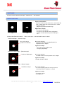
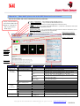
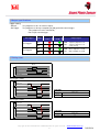
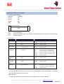
Smart Photo Sensor
SPS02
PRE-INSTASLLED DEMO APPLICATION
GUIDE
Presence Checker (AREA) for Trial
The demo application of Presence Checker (AREA) for Trial has already been pre-installed
to the purchased Smart Photo Sensor (SPS02).
Please use SPS02 correctly after reading this guide book.
Please confirm the function and performance by latest data sheet because it will be revised without any notes.
Copyright © 2013 TOSHIBA TELI CORPORATION, All rights reserved. · www.toshiba-teli.co.jp
-1-
D4216012A
ATTENTION
PLEASE CAREFULLY READ THIS CONTRACT BEFORE USING THE DEMO APPLICATION
(DEMO APPLICATION IS SAME AS FOLLOWING SOFTWARE).
YOU MAY USE THE SOFTWARE THAT PRE-INSTALLED IN THE SMART PHOTO
SENSOR DEVELOPED BY COMPANY ONLY AFTER READING AND ACCEPTING THE
TERMS OF THIS CONTRACT. FIRST RUNNING THE SOFTWARE IS DEEMED TO
CONSTITUTE ACCEPTANCE OF THE TERMS OF THIS CONTRACT. DO NOT RUNNING THE
SOFTWARE UNLESS YOU ACCEPT ALL OF THE TERMS OF THIS CONTRACT.
SOFTWARE LICENSE CONTRACT
This Software License Contract (“Contract” hereinafter) made by and between you (whether “you” is a
natural person or a legal person) and Toshiba Teli Corporation (“Company” hereinafter) sets forth
matters that you must observe when using the Software defined in Article 1 hereof. If you are a legal
person, you are responsible for ensuring that all of your employees comply with the terms of this
Contract.
The Japanese version of this Contract constitutes the original version. The Japanese version will
prevail in the event of any inconsistencies between the Japanese and English versions.
Article 1. Definition
1. “Software” refers to the software product for the use of which the Company grants you license under
this Contract.
Article 2. License granted
The Company grants you a nonexclusive and nontransferable license to use the Software in
accordance with the terms of this Contract.
Article 3. Restrictions on use
Copyright © 2013 TOSHIBA TELI CORPORATION, All rights reserved. · www.toshiba-teli.co.jp
-2-
D4216012A
1. You are permitted to use the Software as instructed in the Software user manual.
2. You shall use the Software only to the extent necessary for the purpose of use the Smart Photo
Sensor developed by Company and may not use the Software for purposes other than such
purposes.
3. You shall not reproduce, redistribute, decompile, reverse engineer, disassemble, attempt to derive
the source-code of, decrypt, modify, or create derivative or incorporate into other applications.
4. You may not sell, sublicense, or offer as security to any third party the Software or its accessories.
5. You may not remove from the Software any copyright notices, labels, trademarks, or any other
marks.
6. If the Company corrects any errors (bugs) in the Software, it will provide you with the corrected
Software, software that implements the corrections (“Correction Software” hereinafter), or
information concerning such corrections. All related matters, including the need to deploy the
Correction Software and information concerning such corrections and the timing and method of
such provision, shall be left to the discretion of the Company. The Correction Software provided to
you, if any, shall be deemed to constitute part of the Software.
7. You agree not to take any action that may impair the credibility of or result in damage to the
Company or any third party.
Article 4. Creating and maintaining an operating environment
Use of the Software may require Company-designated equipment, as well as all devices, software,
etc., necessary and incidental thereto. You bear sole responsibility for such devices and software,
including responsibility for the cost thereof and responsibility for establishing, maintaining, and
managing the environment necessary to use the Software.
Article 5. Intellectual property rights
Copyrights and other intellectual property rights to the Software vest in the Company. This Contract
does not license or assign any intellectual property rights other than the rights specifically granted
Copyright © 2013 TOSHIBA TELI CORPORATION, All rights reserved. · www.toshiba-teli.co.jp
-3-
D4216012A
hereunder.
Article 6. No warranty or liability
1. The Software is provided on an as-is basis by the Company without warranties of any kind. The
Company makes no warranty, express or implied, with respect to the Software, including warranty of
merchantability, fitness for a particular purpose, or non-infringement of third-party rights. You agree
to assume all risks concerning the quality, performance, and operation of the Software. The
Company makes no warranty that the Software will operate without interruption, that the Software is
free of defects, or that the functions of the Software will meet your requirements.
2. The Company shall not be liable for any damages (whether ordinary or special or foreseeable or
unforeseeable) related to use of the Software.
Article 7. Compliance
1. In connection with this Contract, you agree to abide by the Foreign Exchange and Foreign Trade
Act, the Export Trade Control Order, the Foreign Exchange Order and ministerial ordinances related
thereto, and the United States Export Administration Act and Regulations (“Relevant Acts”
hereinafter). You agree not to export, reexport, or cause any third party to export the Software,
related products, or information, directly or indirectly, to any destination, natural person, or legal
person, with regard to which such actions are prohibited under the Relevant Acts, without the
permission of the Japanese government or other relevant governments required under the Relevant
Acts. The Company rejects all liability in connection with these issues.
2. You agree to comply with the terms and conditions of all licenses applying to the computer or OS on
which the Software runs.
Article 8. Termination of the license
If you breach any provision of this Contract, the license granted to you hereunder shall terminate
immediately and without notice. In such cases, you must immediately remove the Software and the
Software Alterations from your computer and the equipment, and destroy all relevant documents.
Copyright © 2013 TOSHIBA TELI CORPORATION, All rights reserved. · www.toshiba-teli.co.jp
-4-
D4216012A
Article 9. Governing law and competent court
This Contract shall be governed by the laws of Japan. The Tokyo District Court shall have jurisdiction
over all disputes arising in connection with this Contract.
Article 10. Mutual consultations
Any matters not specifically addressed herein and any questions regarding this Contract shall be
resolved through consultations between you and the Company.
Copyright © 2013 TOSHIBA TELI CORPORATION, All rights reserved. · www.toshiba-teli.co.jp
-5-
D4216012A
1 SOFTWARE
Presence check software(area type)(PREINSTALL SOFTWARE)
2 MAIN FUNCTIONS
(1)Presence check:Area judgement(GPIO output)
Process for detection
The mass in the measurement area is measured, and
"NG" is output when the measured result is smaller
than the set area.
* judgment by the binarization image
Application example
OK
NG
(2)Output data(RS232C network) * Please refer to the
:Presence check for parts
:Presence check for holl in parts and pattern
:Trigger sensor that detects person and object
etc.
communication feature for detail
●Area info output (RS232C output)
Area value output
(number of resolution)
Process for detection
The mass area value (number of pixels) in
inspection area is output
Application example
:Area value grasp of object work
:Size grasp of printing
●Number of blob output (RS232C output)
Number of blob output
Process for detection
The blob number in the inspection area is output.
Application example
Number of blob of object
●Center of gravity output (RS232C output)
Coordinates output
Process for detection
The center of gravity position in the inspection area
is detected, and then coordinates are output.
Application example
: Positioning of object
: Easy alignment
Copyright © 2013 TOSHIBA TELI CORPORATION, All rights reserved. · www.toshiba-teli.co.jp
-6-
D4216012A
3 Operation * More detail ,please refer to the SPS Viewer basic user manual
Start the SPS Viewer and connect Smart Photo Sensor by USB cable
・Left(red):OUT1(Red lamp is
synchronized to GPIO output1
・Start to communication:start communicate with SmartPhotoSensor
・Stop to communication :stop communicate with SmartPhotoSensor
・Reset :Reset SmartPhotoSensor and reload application from flash memory.
・Right(green):OUT0(Green
lamp is synchronized to
GPIO output0
・Write current setting:The set value edited with SPSViewer is saved in PC as backup file, and it saved
in the flash memory of Smart Photo Sensor.
・Write previous setting:The set up information saved in the PC file is written in Smart Photo Sensor.
Also it can update the application file (file: Specified file)
・Quit:Stop communication and quit SPS Viewer
・Graph image of Area Size
Green: Range of set value
Red: out of range of set value
・Number of Blob Counts
・Input image
and process
image are
displayed
・Process time
is displayed
Item
Function
Condition of
image sensing
Binarization level
Mask area
(coordinates)
Exposure time(msec)
Gain(times)
B-thresholdlevelforobject
image
Parameter
0.5-100
1-10
0-255
Greater equal
Less
B-mode
In Range
Out of range
Noise canceling level
Allow Touching border
Measurement
Region
(coordinates)
Judgment
Trigger
Region Left
Region Top
Region Right
Region Bottom
Lower Limit For Area
Upper Limit For Area
Judgment
1-4095
Enable
Disable
0-143
0-175
0-143
0-175
1-25344
1-25344
Manual,Ext
Trigger1,2
Remarks
Set the exposure time
Set the gain
Set the binarization level for object image
It becomes white if the object brightness is more than
threshold , and if it is less than threshold ,it becomes black
It becomes black if the object brightness is more than
threshold , and if it is less than threshold ,it becomes white
If the brightness of the object is a range of threshold 0
and 1, it becomes white.
If the brightness of the object is a range of threshold 0
and 1, it becomes black.
The object is removed if it is less than specified pixel.
The object that touches the inspection area is also detected.
The object that touches the inspection area is not detected.
Set the left boundary of mask area
Set the upper boundary of mask area
Set the right boundary of mask area
Set the lower boundary of mask area
Set the judgment value for upper area
Set the judgment value for lower area
Lower < Area < Upper = 「OK」
Please refer to output specification as next page.
Copyright © 2013 TOSHIBA TELI CORPORATION, All rights reserved. · www.toshiba-teli.co.jp
-7-
D4216012A
4 Output specifications
Trigger setting
・Manual
The judgment result is in real time output.
・Ext Trigger
The judgment result keeps outputting in [ON] period of external trigger
(The judgment result is maintained.)
In0 is input external trigger
Ext Trigger
Judge
Red sign
(Out1)
Green sign
(Out0)
OK
ON
ON
NG
ON
OFF
OK
OFF
ON
NG
ON
OFF
Ext Trigger1
Ext Trigger2
Output signal
Out0:output the judgment result
Out1:output the judgment result
of chip existing
Out0:OK is output as result
Out1:NG is output as result
5 Timing chart
: Manual mode
Manual
SPS
Processing
out0( OK)
OK
out1(No signal)
External
Equipment
: Ext Trigger1 mode
Ext Trigger1
External Trigger
( →SPS:in0)
OFF
ON
SPS
Processing
out0(OK/NG)
OK
out1(Enable)
Enable
Trigger Latency
This table contains the details of the trigger latency in the SPS system.
Exposure Start
Latency (us)
Trigger
18,3
Pre-select
External
Equipment
: Ext Trigger2 mode
Ext Trigger2
External Trigger
( →SPS:in0)
OFF
ON
SPS
Processing
out0( OK)
out1(NG)
OK
NG
Trigger Latency
This table contains the details of the trigger latency in the SPS system.
Exposure Start
Latency (us)
Trigger
18,3
Pre-select
Copyright © 2013 TOSHIBA TELI CORPORATION, All rights reserved. · www.toshiba-teli.co.jp
-8-
D4216012A
6 Communication specifications
(1) Communication protocol
Baud rate
19200bps
Start bit
1bit
Data bit
8bit
Stop bit
1bit
Parity
None
(2) Communication format
S
T
X
E
T
X
DATA
STX
: Start of text (0x02)
DATA
:Send command from PLC→SPS, Receive command from SPS→PLC (Refer to (3) Command)
ETX
:End of text (0x03)
(3) Command
Function
External equipment → SPS
Area of Blob
"AREA"
Number of Blob
"CNTS"
Surroundings
length of Brob
"PEPI"
Blob
"BBOX"
Bounding Box
Blob
Bounding Box
equipment
"*****"
Number of 5 digits(Exp. 00100)
(Pixels)
"CERR"
Invalid command
Number of Blob inside FOV
"*****"
Number of 5 digits
(Pixels)
"CERR"
Invalid command
Surroundings length of Blob
inside FOV (Pixels)
"*****"
Number of 5 digits
"CERR"
Invalid command
Bounding Box of Blob inside FOV
"BBOX,left,top,right,bottom"
(Coordinate)
"BWID"
SPS → External
Area of Blob inside FOV
left
Left edge coordinate of bounding box(3dig)
top
Top edge coordinate of bounding box(3dig)
right
Right edge coordinate of bounding box(3dig)
bottom
Bottom edge coordinate of bounding box(3dig)
"CERR"
Invalid command
Bounding Box of Blob inside FOV
"*****"
Number of 5 digits
(Width)
"CERR"
Invalid command
Bounding Box of Blob inside FOV
"*****"
Number of 5 digits
(Height)
"CERR"
Invalid command
Blob inside FOV
"GRAV,xpos,ypos"
Width
Blob
"BHEI"
Bounding Box
Height
Center of
Gravity Blob
"GRAV"
(Center of gravity)
xpos
X coordinate of center of gravity(3dig)
ypos
Y coordinate of center of gravity(3dig)
"CERR"
Invalid command
※Blob(Binary Large Object)
The especially big island (Two or more pieces are the connected data) made binarization is called Blob
by a kind of the binary data of the image.
※Bounding Box
The boundary (boundary in the detection area) including the entire Blob is indicated.
Copyright © 2013 TOSHIBA TELI CORPORATION, All rights reserved. · www.toshiba-teli.co.jp
-9-
D4216012A