1
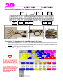
1
Kmrp
/h m
3 St
2
art
225
125
00
200
175
100
00
150
750
0
125
100
500
0
75
50
250
0
25
00
1:4
2.6
0
3:5
3:5
3:5
4:0R105_e-000
4:0
4:0
AC-DOC_SY-KITBASE_Yamaha
2.5
5.0
7.5
0.0
2.5
5.0
4:0
7.5
4:1
0.0
4:1
2.5
4:1
4:126.09.2007
4:2 t
modified
5.0
7.5
0.0
Kit System wiring information for Yamaha R1
R1 ( Type: model year ´04 -´05)
- Annex to the 2D Kit-System user manual The 2D-Kit system uses the motorcycle sensor signals for: RPM (channel: rpm), Throttle (channel: throttle), motor temperature (channel:
T_Mot) and rear wheel speed (channel: V_Rear). These signals will taken directly from the ECU of the bike:
For capturing these signals please follow the explanations step by step:
Pre-work for the connection of the “2D Kit Bike adapter“ with the appropriate cables of the ECU plug
1.
2.
3.
4.
5.
6.
First remove the passenger seat
Dismantle the fuel tank
Dismantle the air cleaner box
Dismantle the ECU adjustment border
Take the ECU from the retaining housing
Take off the wiring harness plug from the ECU
Remove the two screws of the adjustment
border of the ECU retaining housing. Take
out the ECU with flat, broad screwdriver of
the retaining housing.
overview within the filter
box range
First of all you must unlock the bolting device of the ignition box plug. For this the “white plastic nose” has to pushed with light pressure into the plug.
Use a small tool as a screwdriver or the point of a knife for example.
To extract the contact pins you might use a paper clip or a similar tool: Just push the pin carefully out. (use the corresponding pin assignment of your
motorcycle – refer the following table)
Pull out the original cable at the ignition box plug (in the example the yellow/black cable) Afterwards strip the cable with a distance of approximately
3cm from the pin.
Push one of the provided solder shrinking links over the stripped place. Introduce afterwards the corresponding signal from the “2D Kit RWTT loom
into the solder shrinking link.
Solder both cables through warm up the shrinking link. Proceed accordingly with the other 3 bike signals.
Connect the cables from the “2D Kit RWTT loom“ with the cables from the ignition box plug:
•
•
•
•
•
The ECU PIN assignment
2D cable color
PIN 2D (AMP)
Pin at ECU
plug
Cable color at
ECU plug
+12
Volt
Red
R
34
GND
Throttle
RPM
Black
B
25
Speed
(V_Rear)
Yellow
Y
6
Brown
Br
3
Green
G
15
Motor temperature
(T_Mot)
Orange
O
5
11
32
14
41
29
44
Red /
White
RW
Black / Blue
BL
White /
Yellow
WY
Yellow
Yellow /
Black
YB
Green /
White
GW
AC-DOC_SY-KITBASE_Yamaha R105_e-000
Y
Seite 2 / 3
Overview of the ECU pin allocation (view from the wiring harness to the plug)
V_Rear
WY
T_Mot
GW
Throttle
Y
+ 12 V
RW
Battery GND
BL
Pin
Nr.1
RPM
YB
Pin
Nr.23
Connecting the “2D Bike Adapter“ to the 34 pin AMP connector (Kit-Logger)
Make sure that the 34pin AMP connector is not locked: the both small rectangular “white plastic noses“ have to protrude from the connector’s
body. Only in this position the contacts may be slid into the AMP plug and also removed again. In the next step the contacts of the “2D Bike
Adapter“ must be slipped into the correct position of the 34pin AMP plug. When all the contacts are correctly installed, the AMP plug must be
locked again. You might use a screwdriver for that purpose. Press the two “white plastic noses“ into the plug until they become even with the
surface if the connector. The bolting device engages audibly with a click.
Pinning of the AMP plug (Kit-Logger)
AC-DOC_SY-KITBASE_Yamaha R105_e-000
Seite 3 / 3