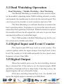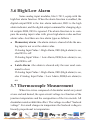
1
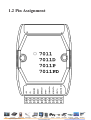
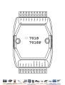
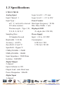
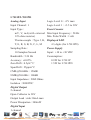
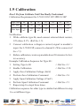
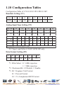
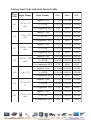
9-10
.
I-7011/11D, I-7011P/11PD,
I-7018, I-7018P
User Manual
Warranty
All products manufactured by factory are warranted
against defective materials for a period of one year from the date
of delivery to the original purchaser.
Warning
Logicbus assume no liability for damages consequent to
the use of this product. Logicbus reserves the right to change this
manual at any time without notice. The information furnished by
Logicbus is believed to be accurate and reliable. However, no responsibility is assumed by Logicbus for its use, nor for any infringements of patents or other rights of third parties resulting from
its use.
Trademark
The names used for identification only maybe registered
trademarks of their respective companies.
[email protected]
www.logicbus.com
Table of Contents
1. Introduction.....................................................5
1.1 More Information.......................................5
1.2 Pin Assignment ..........................................6
1.3 Specifications .............................................8
1.4 Block Diagram ......................................... 11
1.5 Wire Connection ......................................12
1.6 Quick Start ...............................................14
1.7 Default Setting .........................................14
1.8 Jumper Setting .........................................14
1.9 Calibration ...............................................15
1.10 Configuration Tables ..............................16
2. Command.......................................................20
2.1 %AANNTTCCFF ....................................22
2.2 #** ...........................................................23
2.3 #AA..........................................................24
2.4 #AAN .......................................................25
2.5 $AA0........................................................26
2.6 $AA1........................................................27
2.7 $AA2........................................................28
2.8 $AA3........................................................29
2.9 $AA4........................................................30
2.10 $AA5VV ................................................31
2
[email protected]
I-7011, I-7018 User Manual
Rev:B1.0
www.logicbus.com
2.11 $AA6 ......................................................32
2.12 $AA8......................................................33
2.13 $AA8V ...................................................34
2.14 $AA9(Data) ...........................................35
2.15 $AAB .....................................................36
2.16 $AAF .....................................................37
2.17 $AAM ....................................................38
2.18 $AAZ(Data) ...........................................39
2.19 ~AAO(Data) ..........................................40
2.20 ~AAEV ..................................................41
2.21 @AADI..................................................42
2.22 @AADO(Data) ......................................44
2.23 @AAEAT...............................................45
2.24 @AAHI(Data) .......................................46
2.25 @AALO(Data) ......................................47
2.26 @AADA ................................................48
2.27 @AACA ................................................49
2.28 @AARH ................................................50
2.29 @AARL .................................................51
2.30 @AARE .................................................52
2.31 @AACE .................................................53
2.32 ~** .........................................................54
2.33 ~AA0 .....................................................55
2.34 ~AA1 .....................................................56
Rev:B1.0
[email protected]
I-7011, I-7018 User Manual
3
www.logicbus.com
2.35 ~AA2 .....................................................57
2.36 ~AA3EVV .............................................58
2.37 ~AA4 .....................................................59
2.38 ~AA5PPSS.............................................60
3. Application Note ............................................61
3.1 INIT* pin Operation ................................61
3.2 Module Status ..........................................61
3.3 Dual Watchdog Operation ........................62
3.4 Digital Input and Event Counter ..............62
3.5 Digital Output ..........................................62
3.6 High/Low Alarm ......................................63
3.7 Thermocouple Measurement....................63
4
[email protected]
I-7011, I-7018 User Manual
Rev:B1.0
www.logicbus.com
1. Introduction
I-7000 is a family of network data acquisition and control
modules. They provide analog-to-digital, digital-to-analog, digital
input/output, timer/counter and other functions. These modules can
be remote controlled by a set of commands. The common features
of I-7011/11D/11P/11PD/18/18P are given as following :
z
z
z
z
3000VDC Isolated analog input
24-bits sigma-delta ADC to provide excellent accuracy
Thermocouple direct connect with build-in CJC
Software calibration
The I-7011 is a single channel analog input module. The I7011D is the I-7011 with a 4½ digit LED display. The I-7018 is a
8-channel analog input module. The I-7011P/11PD/18P is the enhanced version of I-7011/11D/18. The I-7011P/11PD/18P support
more thermocouple types and enhanced the measure range of some
types.
1.1 More Information
Refer to “I-7000 Bus Converter User Manual” chapter 1
for more information as following:
1.1 I-7000 Overview
1.2 I-7000 Related Documentation
1.3 I-7000 Command Features
1.4 I-7000 System Network Configuration
1.5 I-7000 Dimension
Rev:B1.0
[email protected]
I-7011, I-7018 User Manual
5
www.logicbus.com
1.2 Pin Assignment
6
[email protected]
I-7011, I-7018 User Manual
Rev:B1.0
www.logicbus.com
Rev:B1.0
[email protected]
I-7011, I-7018 User Manual
7
www.logicbus.com
1.3 Specifications
I-7011/I-7011D
Analog Input
Logic Level 0 : +1V max
Logic Level 1 : +3.5 to 30V
Input Channel : 1
Input Type :
Event Counter
mV, V, mA(with external Max Input Frequency : 50 Hz
Min. Pulse Width : 1 mS
125 ohms resistor)
Thermocouple : Type J, K, Displayed LED
T, E, R, S, B, N, C
Sampling Rate :
10 Samples/Second
Bandwidth : 5.24 Hz
Accuracy : ±0.05%
Zero Drift : 0.5µV/°C
Span Drift : 25ppm/°C
4½ digits (for I-7011D)
Power Supply
Input : +10 to +30 VDC
Consumption :
0.9W for I-7011
1.5W for I-7011D
CMR@50/60Hz : 150dB
NMR@50/60Hz : 100dB
Input Impedance : 20M Ohms
Isolation : 3000VDC
Digital Output
2 channel
Open Collector to 30V
Output Load : sink 30mA max
Power Dissipation : 300mW
Digital Input
1 channel
8
[email protected]
I-7011, I-7018 User Manual
Rev:B1.0
www.logicbus.com
I-7011P/I-7011PD
Analog Input
Input Channel : 1
Input Type :
Logic Level 0 : +1V max
Logic Level 1 : +3.5 to 30V
Event Counter
mV, V, mA(with external Max Input Frequency : 50 Hz
Min. Pulse Width : 1 mS
125 ohms resistor)
Thermocouple : Type J, K, Displayed LED
T, E, R, S, B, N, C, L, M
Sampling Rate :
10 Samples/Second
Bandwidth : 5.24 Hz
Accuracy : ±0.05%
Zero Drift : 0.5µV/°C
Span Drift : 25ppm/°C
4½ digits (for I-7011PD)
Power Supply
Input : +10 to +30 VDC
Consumption :
0.9W for I-7011P
1.5W for I-7011PD
CMR@50/60Hz : 150dB
NMR@50/60Hz : 100dB
Input Impedance : 20M Ohms
Isolation : 3000VDC
Digital Output
2 channel
Open Collector to 30V
Output Load : sink 30mA max
Power Dissipation : 300mW
Digital Input
1 channel
Rev:B1.0
[email protected]
I-7011, I-7018 User Manual
9
www.logicbus.com
I-7018
Analog Input
I-7018P
Analog Input
Input Channel :
Input Channel :
8 differential or 6 differen8 differential or 6 differential and 2 single-ended.
Jumper select.
tial and 2 single-ended.
Jumper select.
Input Type :
Analog Input Type :
mV, V, mA(with external
mV, V, mA(with external
125 ohms resistor)
Thermocouple : Type J, K,
125 ohms resistor)
Thermocouple : Type J, K,
T, E, R, S, B, N, C
Sampling Rate :
T, E, R, S, B, N, C, L, M
Sampling Rate :
10 Samples/Second
Bandwidth : 15.7 Hz
10 Samples/Second
Bandwidth : 15.7 Hz
Accuracy : ±0.1%
Zero Drift : 0.5µV/°C
Accuracy : ±0.1%
Zero Drift : 0.5µV/°C
Span Drift : 25ppm/°C
CMR@50/60Hz : 150dB
Span Drift : 25ppm/°C
CMR@50/60Hz : 150dB
NMR@50/60Hz : 100dB
Input Impedance : 20M Ohms
NMR@50/60Hz : 100dB
Input Impedance : 20M Ohms
Overvoltage Protection : ±35V
Isolation : 3000VDC
Overvoltage Protection : ±35V
Isolation : 3000VDC
Power Supply
Input : +10 to +30 VDC
Power Supply
Input : +10 to +30 VDC
Consumption : 1.0W
Consumption : 1.0W
I-7011, I-7018 User Manual
Rev:B1.0
10
[email protected]
www.logicbus.com
1.4 Block Diagram
Rev:B1.0
[email protected]
I-7011, I-7018 User Manual
11
www.logicbus.com
1.5 Wire Connection
I-7011/11D/11P/11PD Analog I-7011/11D/11P/11PD Digital
Input Wire Connection
Output Wire Connection
I-7018/18P Analog Input ChanI-7011/11D/11P/11PD Digital nel 0 to 5 Wire Connection
Input Wire Connection
12
[email protected]
I-7011, I-7018 User Manual
Rev:B1.0
www.logicbus.com
I-7018/18P Analog Input Chan- I-7018/18P Analog Input Channel 6 and 7 Wire Connection, nel 6 and 7 Wire Connection,
while the jumper JP1 setting is while the jumper JP1 setting is
8 differential mode.
INIT* mode.
Rev:B1.0
[email protected]
I-7011, I-7018 User Manual
13
www.logicbus.com
1.6 Quick Start
Refer to “I-7000 Bus Converter User Manual” and “Getting Start” for more detail.
1.7 Default Setting
Default setting for I-7011/11D/11P/11PD/18/18P :
z
z
z
z
z
Address : 01
Analog Input Type : Type 05, -2.5 to +2.5 V
Baudrate : 9600 bps
Checksum disable, 60Hz rejection, engineer unit format
I-7018/18P set as INIT* mode, and the analog input is 6 differential and 2 single-ended.
1.8 Jumper Setting
I-7018/18P : Jumper JP1 for select the pin INIT*/Vin 7Select 8 differential mode, the pin INIT*/Vin7- is set to Vin7Select INIT* mode, the pin INIT*/Vin7- is set to INIT*
14
[email protected]
I-7011, I-7018 User Manual
Rev:B1.0
www.logicbus.com
1.9 Calibration
Don’t Perform Calibrate Until You Really Understand.
Calibration Requirement for I-7011/11D/11P/11PD/18/18P
Type Code
00
01
02
03
04
05
06
Min. Input
0 mV
0 mV
0 mV
0 mV
0V
0V
0 mA
Max Input
+15
mV
+50
mV
+100
mV
+500
mV
+1 V
+2.5 V
+20
mA
Notification :
1 While calibrate type 06, need connect external shunt resistor,
2
125 ohms, 0.1% (Ref Sec.1.5).
Connect calibration voltage(or current) signal to module’s
input. For I-7018/18P, connect to channel 0. (Wire connect ref
Sec.1.5)
3
Before calibration, warm-up module about 30 minutes for better accuracy.
Example Calibration Sequence for Type 00 :
1 Setting Type to 00
-> Ref Sec.2.1.
2
3
Enable Calibration
Apply Zero Calibration Voltage (0mV)
-> Ref Sec.2.20.
4
5
Preform Zero Calibration Command
Apply Span Calibration Voltage (15mV)
-> Ref Sec.2.6.
6
7
Perform Span Calibration Command
Repeat step1 to step6 three times.
-> Ref Sec.2.5.
Calibration sequence for other type is similiar but different in step
1 to set different type.
Rev:B1.0
[email protected]
I-7011, I-7018 User Manual
15
www.logicbus.com
1.10 Configuration Tables
Configuration Table of I-7011/11D/11P/11PD/18/18P :
Baudrate Setting (CC)
C ode
03
04
05
06
Baudrate
12 0 0
2400
4800
9600
07
08
09
19 2 0 0 3 8 4 0 0
0A
57600 115200
Analog Input Type Setting (TT)
Type Code
00
01
Min. Input
- 15 mV
Max Input +15 mV
02
03
04
05
06
- 50 mV - 100 mV - 500 mV
-1 V
- 2.5 V
- 20 mA
+50 mV +100 mV +500 mV
+1 V
+2.5 V
+20 mA
Type Code
0E
0F
10
11
12
13
14
15
16
17
18
T.C. Type
J
K
T
E
R
S
B
N
C
L
M
0
0
0
- 27 0
0
Min Temp. - 210 - 270 - 270 - 270
Max Temp. 760
1372
4 00
1000 1768 1768 1820 1300 2320
- 200 - 200
8 00
100
The temperature is shown in degree Celsius
T.C Type L and M for I-7011P/11PD/18P only.
Data Format Setting (FF)
7
6
*1 * 2
5
4
3
2
0
0
0
0
1
0
*3
*1 :Filter Select : 0 = 60Hz rejection
1 = 50Hz rejection
*2 :Checksum Bit : 0=Disable, 1=Enable
*3 :00 = Engineer Unit Format
01 = Percent Format
10 = 2’s Complement HEX Format
16
[email protected]
I-7011, I-7018 User Manual
Rev:B1.0
www.logicbus.com
Analog input type and data format table
Type
Input Range
Code
00
- 15 to +15
mV
Data Format
- 50 to +50
mV
- 100 to +100
mV
% of F S R
+100.00 +000.00 - 100.00
- 500 to +500
mV
- 1 to +1 V
- 2.5 to +2.5
V
+100.00 +000.00 - 100.00
- 20 to +20
mA
[email protected]
0 0 00
8000
+100.00 +000.00 - 100.00
% of F S R
+100.00 +000.00 - 100.00
7F F F
0 0 00
8000
Engineer Unit
+500.00 +000.00 - 500.00
% of F S R
+100.00 +000.00 - 100.00
7F F F
0 0 00
8000
Engineer Unit
+1.0000 +0.0000 - 1.0000
% of F S R
+100.00 +000.00 - 100.00
7F F F
0 0 00
8000
Engineer Unit
+2.5000 +0.0000 - 2.5000
% of F S R
+100.00 +000.00 - 100.00
7F F F
0 0 00
8000
Engineer Unit
+20.000 +00.000 - 20.000
% of F S R
+100.00 +000.00 - 100.00
2's complement HEX
Rev:B1.0
7F F F
Engineer Unit
2's complement HEX
06
8000
% of F S R
2's complement HEX
05
0 0 00
+50.000 +00.000 - 50.000
2's complement HEX
04
7F F F
Engineer Unit
2's complement HEX
03
-F.S.
+15.000 +00.000 - 15.000
2's complement HEX
02
Ze ro
Engineer Unit
2's complement HEX
01
+F.S.
7F F F
I-7011, I-7018 User Manual
0 0 00
8000
17
www.logicbus.com
Type
Input Range
Code
0E
0F
10
11
12
13
14
15
J Type
- 210 to 760
degree Celsius
K Type
- 270 to 1372
degree Celsius
T Type
- 270 to 400
degree Celsius
E Type
- 270 to 1000
degree Celsius
R Type
0 to 1768
degree Celsius
S Type
0 to 1768
degree Celsius
B Type
0 to 1820
degree Celsius
N Type
- 270 to 1300
degree Celsius
18
[email protected]
Data Format
+F.S.
Ze ro
-F.S.
Engineer Unit
+760.00 +00.000 - 210.00
% of F S R
+100.00 +000.00 - 027.63
2's complement HEX
7F F F
0 0 00
DCA2
Engineer Unit
+1372.0 +00.000 - 0270.0
% of F S R
+100.00 +000.00 - 019.68
2's complement HEX
7F F F
0 0 00
E6D0
Engineer Unit
+400.00 +000.00 - 270.00
% of F S R
+100.00 +000.00 - 067.50
2's complement HEX
7F F F
0 0 00
A99A
Engineer Unit
+1000.0 +000.00 - 0270.0
% of F S R
+100.00 +000.00 - 027.00
2's complement HEX
7F F F
0 0 00
DD71
Engineer Unit
+1768.0 +0000.0 +0000.0
% of F S R
+100.00 +0000.0 +0000.0
2's complement HEX
7F F F
0 0 00
0000
Engineer Unit
+1786.0 +0.0000 +0000.0
% of F S R
+100.00 +000.00 +0000.0
2's complement HEX
7F F F
0 0 00
0000
Engineer Unit
+1820.0 +00.000 +0000.0
% of F S R
+100.00 +000.00 +0000.0
2's complement HEX
Engineer Unit
% of F S R
2's complement HEX
7F F F
0 0 00
0000
+1300.0 +00.000 - 0270.0
+100.00 +000.00
7F F F
I-7011, I-7018 User Manual
0 0 00
- 2 0 . 77
E56B
Rev:B1.0
www.logicbus.com
Type
Input Range
Code
16
17*1
18*1
*1
C Type
0 to 2320
degree Celsius
L Type
- 200 to 800
degree Celsius
M Type
- 200 to 100
degree Celsius
Data Format
+F.S.
Ze ro
-F.S.
Engineer Unit
+2320.0 +00.000 +00.000
% of F S R
+100.00 +000.00 +000.00
2's complement HEX
7F F F
0 0 00
0000
Engineer Unit
+800.00 +00.000 - 200.00
% of F S R
+100.00 +000.00 - 025.00
2's complement HEX
7F F F
0 0 00
E000
Engineer Unit
+100.00 +000.00 - 200.00
% of F S R
+050.00 +000.00 - 100.00
2's complement HEX
400 0
0 0 00
8000
: Only available for I- 7011P, I- 7011PD and I- 7018P
Rev:B1.0
[email protected]
I-7011, I-7018 User Manual
19
www.logicbus.com
2. Command
Command Format : (Leading)(Address)(Command)[CHK](cr)
Response Format : (Leading)(Address)(Data)[CHK](cr)
[CHK] 2-character checksum
(cr)
end-of-command character, character return(0x0D)
Ge ne ral Command Se ts
Command
Re s pons e
De s cription
Se ction
%AANNTTCCFF !AA
Set Module Configuration
Sec.2.1
#**
No Response
Synchronized Sampling
Sec.2.2
#AA
>(Data)
Read Analog Input
Sec.2.3
#AAN
>(Data)
Read Analog Input from
channel N
Sec.2.4
$AA0
!AA
Perform Span Calibration
Sec.2.5
$AA1
!AA
Perform Zero Calibration
Sec.2.6
$AA2
!AATTCCFF
Read Configuration
Sec.2.7
$AA3
>(Data)
Read CJC Temperature
Sec.2.8
$AA4
>AAS(Data)
Read Synchronized Data
Sec.2.9
$AA5VV
!AA
Set Channel Enable
Sec.2.10
$AA6
!AAVV
Read Channel Status
Sec.2.11
$AA8
!AAV
Read LED Configuration
Sec.2.12
$AA8V
!AA
Set LED Configuration
Sec.2.13
$AA9(Data)
!AA
Set CJC Offset Value
Sec.2.14
$AAB
!AAS
T.C. Open Dectection
Sec.2.15
$AAF
!AA(Data)
Read Firmware Version
Sec.2.16
$AAM
!AA(Data)
Read Module Name
Sec.2.17
$AAZ(Data)
!AA
Send LED Data
Sec.2.18
20
[email protected]
I-7011, I-7018 User Manual
Rev:B1.0
www.logicbus.com
Ge ne ral Command Se ts (Continue d)
~AAO(Data)
!AA
Set Module Name
Sec.2.19
~AAEV
!AA
Enable/Disable Calibration Sec.2.20
Digital Input/Output, Alarm and Eve nt Counte r Command Se ts
@AADI
!AASOOII
Read Digital I/O and
Alarm Status
Sec.2.21
@AADO(Data)
!AA
Set Digital Output
Sec.2.22
@AAEAT
!AA
Enable Alarm
Sec.2.23
@AAHI(Data)
!AA
Set High Alarm
Sec.2.24
@AALO(Data)
!AA
Set Low Alarm
Sec.2.25
@AADA
!AA
Disable Alarm
Sec.2.26
@AACA
!AA
Clear Latch Alarm
Sec.2.27
@AARH
!AA(Data)
Read High Alarm
Sec.2.28
@AARL
!AA(Data)
Read Low Alarm
Sec.2.29
@AARE
!AA(Data)
Read Event Counter
Sec.2.30
@AACE
!AA
Clear Event Counter
Sec.2.31
Hos t Watchdog Command Se ts
~ **
No Response
Host OK
Sec.2.32
~AA0
!AASS
Read Module Status
Sec.2.33
~AA1
!AA
Reset Module Status
Sec.2.34
~AA2
!AAVV
Read Host Watchdog
Timeout Value
Sec.2.35
~AA3EVV
!AA
Set Host Watchdog
Timeout Value
Sec.2.36
~AA4
!AAPPSS
Read PowerOn Value and
Safe Value
Sec.2.37
~AA5PPSS
!AA
Set PowerOn Value and
Safe Value
Sec.2.38
Rev:B1.0
[email protected]
I-7011, I-7018 User Manual
21
www.logicbus.com
2.1 %AANNTTCCFF
Description : Set module Configuration
Syntax : %AANNTTCCFF[CHK](cr)
%
a delimiter character
AA
address of setting module(00 to FF)
NN
new address for setting module(00 to FF)
TT
new type for setting module (Ref Sec.1.10)
CC
new baudrate for setting module (Ref Sec.1.10)
FF
new data format for setting module (Ref Sec.1.10)
When changing the baudrate or checksum, it is necessary
to short the pin INIT* to ground.
Response : Valid Command :
!AA[CHK](cr)
Invalid Command :
?AA[CHK](cr)
Syntax error or communication error may get no
response.
!
delimiter for valid command
?
delimiter for invalid command. While change baudrate or
checksum setting without shorting INIT* to ground, the
module will return invalid command.
AA
address of response module(00 to FF)
Example :
Command : %0102050600
Receive : !02
Change address from 01 to 02, return success.
Related Command :
Sec.2.7 $AA2
Related Topics :
Sec.1.10 Configuration Tables, Sec.3.1 INIT* pin Operation
22
[email protected]
I-7011, I-7018 User Manual
Rev:B1.0
www.logicbus.com
2.2 #**
Description : Synchronized Sampling
Syntax : #**[CHK](cr)
#
**
a delimiter character
synchronized sampling command
Response : No response
Example :
Command : $014
Receive : ?01
Read synchronized sampling data, return no data valid.
Command : #**
No response
Send synchronized sampling command.
Command : $014
Receive : >011+025.123
First read, get status=1, first read.
Command : $014
Receive : >010+025.123
Second read, get status=0, have readed.
Related Command :
Sec.2.9 $AA4
Note : The command is for I-7011/11D/11P/11PD only
Rev:B1.0
[email protected]
I-7011, I-7018 User Manual
23
www.logicbus.com
2.3 #AA
Description : Read Analog Input
Syntax : #AA[CHK](cr)
#
AA
delimiter character
address of reading module(00 to FF)
Response : Valid Command : >(Data)[CHK](cr)
Syntax error or communication error may get no
response.
delimiter for valid command
>
(Data) analog input value, reference Sec.1.10 for its format.
For I-7018/18P, the data is the combination for each channel respectively.
Example :
Command : #01
Receive : >+02.635
Read address 01, return data success.
Command : #02
Receive : >4C53
Read address 02, return data in HEX format success.
Command : #04
Receive : >+05.123+04.153+07.234-02.356+10.000-05.133+02.
345+08.234
Module address 04 is I-7018. Read address 04, get analog input data of 8 channels.
Related Command :
Sec.2.1 %AANNTTCCFF, Sec.2.7 $AA2
Related Topics :
Sec.1.10 Configuration Tables
24
[email protected]
I-7011, I-7018 User Manual
Rev:B1.0
www.logicbus.com
2.4 #AAN
Description : Read Analog Input from channel N
Syntax : #AAN[CHK](cr)
#
AA
delimiter character
address of reading module (00 to FF)
N
channel to read, from 0 to 7
Response : Valid Command :
>(Data)[CHK](cr)
Invalid Command :
?AA[CHK](cr)
Syntax error or communication error may get no
>
response.
delimiter for valid command
?
AA
delimiter for invalid command
address of response module(00 to FF)
(Data) analog input value, reference Sec.1.10 for its format
Example :
Command : #032
Receive : >+02.513
Read address 03 channel 2, get data success.
Command : #029
Receive : ?02
Read address 02 channel 9, return error channel number.
Related Command :
Sec.2.1 %AANNTTCCFF, Sec.2.7 $AA2
Related Topics :
Sec.1.10 Configuration Tables
Note : The command is for I-7018/18P only
Rev:B1.0
[email protected]
I-7011, I-7018 User Manual
25
www.logicbus.com
2.5 $AA0
Description : Perform Span Calibration
Syntax : $AA0[CHK](cr)
$
AA
delimiter character
address of setting module (00 to FF)
0
command for performing span calibration
Response : Valid Command :
!AA[CHK](cr)
Invalid Command :
?AA[CHK](cr)
Syntax error or communication error may get no
!
?
response.
delimiter for valid command
delimiter for invalid command or the calibration is not
enabled
AA
address of response module(00 to FF)
Example :
Command : $010
Receive : !01
Perform address 01 span calibration, return success.
Command : $020
Receive : ?02
Perform address 02 span calibration, return the calibration is
not enabled before perform calibration command.
Related Command :
Sec.2.6 $AA1, Sec.2.20 ~AAEV
Related Topics :
Sec.1.9 Calibration
26
[email protected]
I-7011, I-7018 User Manual
Rev:B1.0
www.logicbus.com
2.6 $AA1
Description : Perform Zero Calibration
Syntax : $AA1[CHK](cr)
$
AA
delimiter character
address of setting module (00 to FF)
1
command for performing zero calibration
Response : Valid Command :
!AA[CHK](cr)
Invalid Command :
?AA[CHK](cr)
Syntax error or communication error may get no
!
?
response.
delimiter for valid command
delimiter for invalid command or the calibration is not
enabled
AA
address of response module(00 to FF)
Example :
Command : $011
Receive : !01
Perform address 01 zero calibration, return success.
Command : $021
Receive : ?02
Perform address 02 zero calibration, return the calibration is
not enabled before perform calibration command.
Related Command :
Sec.2.5 $AA0, Sec.2.20 ~AAEV
Related Topics :
Sec.1.9 Calibration
Rev:B1.0
[email protected]
I-7011, I-7018 User Manual
27
www.logicbus.com
2.7 $AA2
Description : Read Configuration
Syntax : $AA2[CHK](cr)
$
AA
delimiter character
address of reading module (00 to FF)
2
command for reading configuration
Response : Valid Command :
!AATTCCFF[CHK](cr)
Invalid Command :
?AA[CHK](cr)
Syntax error or communication error may get no
!
response.
delimiter for valid command
?
AA
delimiter for invalid command
address of response module(00 to FF)
TT
CC
type code of module (reference Sec.1.10)
baudrate code of module (reference Sec.1.10)
FF
data format of module (reference Sec.1.10)
Example :
Command : $012
Receive : !01050600
Read address 01 configuration, return success.
Command : $022
Receive : !02030602
Read address 02 configuration, return success.
Related Command :
Sec2.1 %AANNTTCCFF
Related Topics :
Sec.1.10 Configuration Tables, Sec.3.1 INIT* pin Operation
28
[email protected]
I-7011, I-7018 User Manual
Rev:B1.0
www.logicbus.com
2.8 $AA3
Description : Read CJC Temperature
Syntax : $AA3[CHK](cr)
$
AA
delimiter character
address of reading module (00 to FF)
3
command for reading CJC temperature
Response : Valid Command :
>(Data)[CHK](cr)
Invalid Command :
?AA[CHK](cr)
Syntax error or communication error may get no
>
response.
delimiter for valid command
?
AA
delimiter for invalid command
address of response module(00 to FF)
(Data) CJC temperature in degree Celsius.
Example :
Command : $033
Receive : >+0025.4
Read address 03 CJC temperature, return 25.4°C.
Related Command :
Sec.2.14 $AA9(Data)
Rev:B1.0
[email protected]
I-7011, I-7018 User Manual
29
www.logicbus.com
2.9 $AA4
Description : Read Synchronized Data
Syntax : $AA4[CHK](cr)
$
AA
delimiter character
address of reading module (00 to FF)
4
command for reading synchronized data
Response : Valid Command :
>AAS(Data)[CHK](cr)
Invalid Command :
?AA[CHK](cr)
Syntax error or communication error may get no
!
response.
delimiter for valid command
?
delimiter for invalid command or the module does not receive command #** before the command $AA4.
AA
S
address of response module(00 to FF)
status of synchronized data, 1 = first time reading, 0 = has
been readed
(Data) synchronized data, format reference Sec.1.10
Example :
See example of Sec.2.2 #**
Related Command :
Sec.2.2 #**
Note : The command is for I-7011/11D/11P/11PD only
30
[email protected]
I-7011, I-7018 User Manual
Rev:B1.0
www.logicbus.com
2.10 $AA5VV
Description : Set Channel Enable
Syntax : $AA5VV[CHK](cr)
$
AA
delimiter character
address of setting module (00 to FF)
5
VV
command for settting channel enable
channel enable/disable, 00 is all disabled, and FF is all
enabled.
Response : Valid Command :
!AA[CHK](cr)
Invalid Command :
?AA[CHK](cr)
Syntax error or communication error may get no
!
response.
delimiter for valid command
?
AA
delimiter for invalid command
address of response module(00 to FF)
Example :
Command : $0155A
Receive : !01
Set address 01 enable channel 1,3,4,6 and disable channel 0,2,
5,7, return success.
Command : $016
Receive : !015A
Read address 01 channel status, return channel 1,3,4,6 enable
and channel 0,2,5,7 disable.
Related Command :
Sec.2.11 $AA6
Note : The command is for I-7018/18P only
Rev:B1.0
[email protected]
I-7011, I-7018 User Manual
31
www.logicbus.com
2.11 $AA6
Description : Read Channel Status
Syntax : $AA6[CHK](cr)
$
AA
delimiter character
address of reading module (00 to FF)
6
command for reading channel status
Response : Valid Command :
!AAVV[CHK](cr)
Invalid Command :
?AA[CHK](cr)
Syntax error or communication error may get no
!
response.
delimiter for valid command
?
AA
delimiter for invalid command
address of response module(00 to FF)
VV
channel enable/disable, 00 is all disabled, and FF is all
enabled.
Example :
Command : $015A5
Receive : !01
Set address 01 enable channel 0,2,5,7 and disable channel 1,3,
4,6 , return success.
Command : $016
Receive : !01A5
Read address 01 channel status, return channel 0,2,5,7 enable
and channel 1,3,4,6 disable.
Related Command :
Sec2.10 $AA5VV
Note : The command is for I-7018/18P only
32
[email protected]
I-7011, I-7018 User Manual
Rev:B1.0
www.logicbus.com
2.12 $AA8
Description : Read LED Configuration
Syntax : $AA8[CHK](cr)
$
AA
delimiter character
address of reading module (00 to FF)
8
command for setting LED configuration
Response : Valid Command :
!AAV[CHK](cr)
Invalid Command :
?AA[CHK](cr)
Syntax error or communication error may get no
!
response.
delimiter for valid command
?
AA
delimiter for invalid command
address of response module(00 to FF)
V
LED configuration
1=module control, 2=host control
Example :
Command : $018
Receive : !011
Read address 01 LED configuration, return module control.
Command : $028
Receive : !012
Read address 02 LED configuration, return host control.
Related Command :
Sec2.13 $AA8V, Sec2.18 $AAZ(Data)
Note : The command is for I-7011D/11PD only
Rev:B1.0
[email protected]
I-7011, I-7018 User Manual
33
www.logicbus.com
2.13 $AA8V
Description : Set LED Configuration
Syntax : $AA8V[CHK](cr)
$
AA
delimiter character
address of setting module (00 to FF)
8
V
command for setting LED configuration
1=Set LED to module, 2=Set LED to host
Response : Valid Command :
Invalid Command :
!AA[CHK](cr)
?AA[CHK](cr)
Syntax error or communication error may get no
response.
!
?
delimiter for valid command
delimiter for invalid command
AA
address of response module(00 to FF)
Example :
Command : $0182
Receive : !01
Set address 01 LED to host control, return success.
Command : $0281
Receive : !02
Set address 02 LED to module control, return success.
Related Command :
Sec2.12 $AA8, Sec2.18 $AAZ(Data)
Note : The command is for I-7011D/11PD only
34
[email protected]
I-7011, I-7018 User Manual
Rev:B1.0
www.logicbus.com
2.14 $AA9(Data)
Description : Set CJC Offset Value
Syntax : $AA9(Data)[CHK](cr)
$
AA
delimiter character
address of setting module (00 to FF)
9
command for setting CJC offset value
(Data) CJC offset value comprises a sign and 4 hexadecimal digits,
from -1000 to +1000, each count is 0.01°C.
Response : Valid Command :
!AA[CHK](cr)
Invalid Command :
?AA[CHK](cr)
Syntax error or communication error may get no
!
response.
delimiter for valid command
?
AA
delimiter for invalid command
address of response module (00 to FF)
Example :
Command : $019+0010
Receive : !01
Set address 01 CJC offset increase 16 counts (+0.16°C), return
success.
Related Command :
Sec.2.8 $AA3
Rev:B1.0
[email protected]
I-7011, I-7018 User Manual
35
www.logicbus.com
2.15 $AAB
Description : Thremocouple Open Detection
Syntax : $AAB[CHK](cr)
$
AA
delimiter character
address of reading module (00 to FF)
B
command for reading thremocouple open status
Response : Valid Command :
!AAS[CHK](cr)
Invalid Command :
?AA[CHK](cr)
Syntax error or communication error may get no
!
response.
delimiter for valid command
?
AA
delimiter for invalid command
address of response module(00 to FF)
S
0=close-loop detection
1=open-circuit detection, need to check the thermocouple
Example :
Command : $01B
Receive : !010
Read address 01 thermocouple open status, return the thermocouple is close-loop.
Note : The command is for I-7011/11D/11P/11PD only
36
[email protected]
I-7011, I-7018 User Manual
Rev:B1.0
www.logicbus.com
2.16 $AAF
Description : Read Firmware Version
Syntax : $AAF[CHK](cr)
$
AA
delimiter character
address of reading module (00 to FF)
F
command for reading firmware version
Response : Valid Command :
!AA(Data)[CHK](cr)
Invalid Command :
?AA[CHK](cr)
Syntax error or communication error may get no
!
response.
delimiter for valid command
?
AA
delimiter for invalid command
address of response module(00 to FF)
(Data) firmware version of module
Example :
Command : $01F
Receive : !01A2.0
Read address 01 firmware version, return version A2.0.
Command : $02F
Receive : !01B1.1
Read address 02 firmware version, return version B1.1.
Rev:B1.0
[email protected]
I-7011, I-7018 User Manual
37
www.logicbus.com
2.17 $AAM
Description : Read Module Name
Syntax : $AAM[CHK](cr)
$
AA
delimiter character
address of reading module (00 to FF)
M
command for reading module name
Response : Valid Command :
!AA(Data)[CHK](cr)
Invalid Command :
?AA[CHK](cr)
Syntax error or communication error may get no
!
response.
delimiter for valid command
?
AA
delimiter for invalid command
address of response module(00 to FF)
(Data) Name of module
Example :
Command : $01M
Receive : !017018
Read address 01 module name, return name 7018.
Command : $03M
Receive : !037011D
Read address 03 module name, return name 7011D.
Related Command :
Sec.2.19 ~AAO(Data)
38
[email protected]
I-7011, I-7018 User Manual
Rev:B1.0
www.logicbus.com
2.18 $AAZ(Data)
Description : Set LED Data
Syntax : $AAZ(Data)[CHK](cr)
$
AA
delimiter character
address of setting module (00 to FF)
Z
command for setting LED data
(Data) data for show on the LED, from -19999. to +19999. The
data need sign, 5 digits and decimal point.
Response : Valid Command :
!AA[CHK](cr)
Invalid Command :
?AA[CHK](cr)
Syntax error or communication error may get no
!
?
response.
delimiter for valid command
delimiter for invalid command or LED not set to host control
AA
address of response module (00 to FF)
Example :
Command : $01Z+123.45
Receive : !01
Send address 01 LED data +123.45, return success.
Command : $02Z+512.34
Receive : ?02
Send address 02 LED data +512.34, return the LED is not setting in the host mode.
Related Command :
Sec.2.12 $AA8, Sec2.13 $AA8V
Note : The command is for I-7011D/11PD only
Rev:B1.0
[email protected]
I-7011, I-7018 User Manual
39
www.logicbus.com
2.19 ~AAO(Data)
Description : Set Module Name
Syntax : ~AAO(Data)[CHK](cr)
~
AA
delimiter character
address of setting module (00 to FF)
O
command for setting module name
(Data) new name for module, max 6 characters
Response : Valid Command :
Invalid Command :
!AA[CHK](cr)
?AA[CHK](cr)
Syntax error or communication error may get no
response.
!
?
delimiter for valid command
delimiter for invalid command
AA
address of response module(00 to FF)
Example :
Command : ~01O7018
Receive : !01
Set address 01 module name to 7018, return success.
Command : $01M
Receive : !017018
Read address 01 module name, return 7018.
Related Command :
Sec.2.17 $AAM
40
[email protected]
I-7011, I-7018 User Manual
Rev:B1.0
www.logicbus.com
2.20 ~AAEV
Description : Enable/Disable Calibration
Syntax : ~AAEV[CHK](cr)
~
AA
delimiter character
address of setting module (00 to FF)
E
V
command for enable/disable calibration
1=enable calibration, 0=disable calibration
Response : Valid Command :
Invalid Command :
!AA[CHK](cr)
?AA[CHK](cr)
Syntax error or communication error may get no
response.
!
?
delimiter for valid command
delimiter for invalid command
AA
address of response module(00 to FF)
Example :
Command : $010
Receive : ?01
Perform address 01 span calibration, return it is not ready for
calibration.
Command : ~01E1
Receive : !01
Set address 01 to enable calibration, return success.
Command : $010
Receive : !01
Preform address 01 span calibration, return success.
Related Command :
Sec.2.5 $AA0, Sec.2.6 $AA1
Related Topic :
Sec.1.9 Calibration
Rev:B1.0
[email protected]
I-7011, I-7018 User Manual
41
www.logicbus.com
2.21 @AADI
Description : Read Digital I/O and Alarm Status
Syntax : @AADI[CHK](cr)
@
AA
delimiter character
address of reading module (00 to FF)
DI
command for reading digital I/O and alarm status
Response :Valid Command :
!AASOOII[CHK](cr)
Invalid Command :
?AA[CHK](cr)
Syntax error or communication error may get no
!
response.
delimiter for valid command
?
AA
delimiter for invalid command
address of response module(00 to FF)
S
alarm enable status, 0=alarm disable, 1=momentary alarm
enabled, 2=latch alarm enabled.
OO
digital output status, 00=DO0 off, DO1 off, 01=DO0 on,
DO1 off, 02=DO0 off, DO1 on, 03=OD0 on, DO1 on.
II
digital input status, 00=input low level, 01=input high level.
Example :
Command : @01DI
Receive : !0100001
Read address 01 digital I/O status, return alarm disable, digital
outputs all off, and digital input high level.
Command : @02DI
Receive : !0210100
Read address 02 digital I/O status, return momentary alarm
enable, high alarm is clear, low alarm is set, and digital input
is high.
42
[email protected]
I-7011, I-7018 User Manual
Rev:B1.0
www.logicbus.com
Related Command :
Sec.2.22 @AADO(Data), Set.2.23 @AAEAT, Sec.2.26 @AADA
Related Topic :
Sec.3.4 Digital Input and Event Counter, Sec.3.5 Digital Output,
Sec.3.6 High/Low Alarm
Note : The command is for I-7011/11D/11P/11PD only
Rev:B1.0
[email protected]
I-7011, I-7018 User Manual
43
www.logicbus.com
2.22 @AADO(Data)
Description : Set Digital Output
Syntax : @AADI[CHK](cr)
@
AA
delimiter character
address of setting module (00 to FF)
DO
command for setting digital output
(Data) output value, 00=DO0 off, DO1 off, 01=DO0 on, DO1 off,
02=DO0 off, DO1 on, 03=DO0 on, DO1 on
Response : Valid Command :
!AA[CHK](cr)
Invalid Command :
?AA[CHK](cr)
Syntax error or communication error may get no
!
?
response.
delimiter for valid command
delimiter for invalid command. While the alarm is enabled,
the command will return invalid.
AA
address of response module(00 to FF)
Example :
Command : @01DO00
Receive : !01
Set address 01 digital output 00, return success.
Related Command :
Sec.2.21 @AADI, Set.2.23 @AAEAT, Sec.2.26 @AADA
Related Topic :
Sec.3.5 Digital Output
Note : The command is for I-7011/11D/11P/11PD only
44
[email protected]
I-7011, I-7018 User Manual
Rev:B1.0
www.logicbus.com
2.23 @AAEAT
Description : Enable Alarm
Syntax : @AAEAT[CHK](cr)
@
AA
delimiter character
address of setting module (00 to FF)
EA
T
command for enable alarm.
alarm type, M=momentary alarm, L=latch alarm.
Response : Valid Command :
Invalid Command :
!AA[CHK](cr)
?AA[CHK](cr)
Syntax error or communication error may get no
response.
!
?
delimiter for valid command
delimiter for invalid command
AA
address of response module(00 to FF)
Example :
Command : @01EAM
Receive : ?01
Set address 01 momentary alarm, return success.
Related Command :
Sec.2.26 @AADA, Sec.2.27 @AACA
Related Topic :
Sec.3.6 High/Low Alarm
Note : The command is for I-7011/11D/11P/11PD only
Rev:B1.0
[email protected]
I-7011, I-7018 User Manual
45
www.logicbus.com
2.24 @AAHI(Data)
Description : Set High Alarm
Syntax : @AADI[CHK](cr)
@
AA
delimiter character
address of setting module (00 to FF)
HI
command for setting high alarm value
(Data) high alarm values, data format is in engineer unit format.
Response : Valid Command :
Invalid Command :
!AA[CHK](cr)
?AA[CHK](cr)
Syntax error or communication error may get no
response.
!
?
delimiter for valid command
delimiter for invalid command
AA
address of response module(00 to FF)
Example :
Command : @01HI+2.5000 Receive : !01
Set address 01 high alarm +2.5000, return success.
Related Command :
Sec.2.23 @AAEAT, Sec.2.28 @AARH
Related Topic :
Sec.3.6 High/Low Alarm
Note : The command is for I-7011/11D/11P/11PD only
46
[email protected]
I-7011, I-7018 User Manual
Rev:B1.0
www.logicbus.com
2.25 @AALO(Data)
Description : Set Low Alarm
Syntax : @AADI[CHK](cr)
@
AA
delimiter character
address of setting module (00 to FF)
LO
command for setting high alarm value
(Data) high alarm values, data format is in engineer unit format.
Response : Valid Command :
Invalid Command :
!AA[CHK](cr)
?AA[CHK](cr)
Syntax error or communication error may get no
response.
!
?
delimiter for valid command
delimiter for invalid command
AA
address of response module(00 to FF)
Example :
Command : @01LO-2.5000 Receive : !01
Set address 01 low alarm -2.5000, return success.
Related Command :
Sec.2.23 @AAEAT, Sec.2.29 @AARL
Related Topic :
Sec.3.6 High/Low Alarm
Note : The command is for I-7011/11D/11P/11PD only
Rev:B1.0
[email protected]
I-7011, I-7018 User Manual
47
www.logicbus.com
2.26 @AADA
Description : Disable Alarm
Syntax : @AADA[CHK](cr)
@
AA
delimiter character
address of setting module (00 to FF)
DA
command for disable alarm
Response : Valid Command :
!AA[CHK](cr)
Invalid Command :
?AA[CHK](cr)
Syntax error or communication error may get no
!
response.
delimiter for valid command
?
AA
delimiter for invalid command
address of response module(00 to FF)
Example :
Command : @01DA
Receive : !01
Disable address 01 alarm, return success.
Related Command :
Sec.2.23 @AAEAT
Related Topic :
Sec.3.6 High/Low Alarm
Note : The command is for I-7011/11D/11P/11PD only
48
[email protected]
I-7011, I-7018 User Manual
Rev:B1.0
www.logicbus.com
2.27 @AACA
Description : Clear Latch Alarm
Syntax : @AACA[CHK](cr)
@
delimiter character
AA
address of setting module (00 to FF)
CA
command for clear latch alarm
Response : Valid Command :
!AA[CHK](cr)
Invalid Command :
?AA[CHK](cr)
Syntax error or communication error may get no
response.
!
delimiter for valid command
?
delimiter for invalid command
AA
address of response module(00 to FF)
Example :
Command : @01DI
Receive : !0120101
Read address 01 digital input, return latch alarm mode, low
alarm is set.
Command : @01CA
Receive : !01
Clear address 01 latch alarm, return success.
Command : @01DI
Receive : !0120001
Read address 01 digital input, return latch alarm mode, both
alarms are clear.
Related Command :
Sec.2.21 @AADI, Sec.2.23 @AAEAT, Sec.2.26 @AADA
Related Topic :
Sec.3.6 High/Low Alarm
Note : The command is for I-7011/11D/11P/11PD only
Rev:B1.0
[email protected]
I-7011, I-7018 User Manual
49
www.logicbus.com
2.28 @AARH
Description : Read High Alarm
Syntax : @AARH[CHK](cr)
@
AA
delimiter character
address of reading module (00 to FF)
RH
command for reading high alarm
Response : Valid Command :
!AA(Data)[CHK](cr)
Invalid Command :
?AA[CHK](cr)
Syntax error or communication error may get no
!
response.
delimiter for valid command.
?
AA
delimiter for invalid command.
address of response module(00 to FF)
(Data) high alarm value in engineer unit format.
Example :
Command : @01RH
Receive : !01+2.5000
Read address 01 high alarm, return +2.5000.
Related Command :
Sec.2.24 @AAHI(Data)
Related Topic :
Sec.3.6 High/Low Alarm
Note : The command is for I-7011/11D/11P/11PD only
50
[email protected]
I-7011, I-7018 User Manual
Rev:B1.0
www.logicbus.com
2.29 @AARL
Description : Read Low Alarm
Syntax : @AARH[CHK](cr)
@
AA
delimiter character
address of reading module (00 to FF)
RL
command for reading low alarm
Response : Valid Command :
!AA(Data)[CHK](cr)
Invalid Command :
?AA[CHK](cr)
Syntax error or communication error may get no
!
response.
delimiter for valid command.
?
AA
delimiter for invalid command.
address of response module(00 to FF)
(Data) low alarm value in engineer unit format.
Example :
Command : @01RL
Receive : !01-2.5000
Read address 01 low alarm, return -2.5000.
Related Command :
Sec.2.25 @AALO(Data)
Related Topic :
Sec.3.6 High/Low Alarm
Note : The command is for I-7011/11D/11P/11PD only
Rev:B1.0
[email protected]
I-7011, I-7018 User Manual
51
www.logicbus.com
2.30 @AARE
Description : Read Event Counter
Syntax : @AARE[CHK](cr)
@
AA
delimiter character
address of reading module (00 to FF)
RE
command for reading event counter
Response : Valid Command :
!AA(Data)[CHK](cr)
Invalid Command :
?AA[CHK](cr)
Syntax error or communication error may get no
!
response.
delimiter for valid command
?
AA
delimiter for invalid command
address of response module(00 to FF)
(Data) event counter value, from 00000 to 65535.
Example :
Command : @01RE
Receive : !0101234
Read address 01 event counter, return 1234.
Related Command :
Sec.2.31 @AACE
Related Topic :
Sec.3.4 Digital Input and Event Counter
Note : The command is for I-7011/11D/11P/11PD only
52
[email protected]
I-7011, I-7018 User Manual
Rev:B1.0
www.logicbus.com
2.31 @AACE
Description : Clear Event Counter
Syntax : @AACE[CHK](cr)
@
AA
delimiter character
address of setting module (00 to FF)
CE
command for clear event counter
Response : Valid Command :
!AA[CHK](cr)
Invalid Command :
?AA[CHK](cr)
Syntax error or communication error may get no
!
response.
delimiter for valid command
?
AA
delimiter for invalid command
address of response module(00 to FF)
Example :
Command : @01RE
Receive : !0101234
Read address 01 event counter, return 1234.
Command : @01CE
Receive : !01
Clear address 01 event counter, return success.
Command : @01RE
Receive : !0100000
Read address 01 event counter, return 0.
Related Command :
Sec.2.30 @AARE
Related Topic :
Sec.3.4 Digital Input and Event Counter
Note : The command is for I-7011/11D/11P/11PD only
Rev:B1.0
[email protected]
I-7011, I-7018 User Manual
53
www.logicbus.com
2.32 ~**
Description : Host OK.
Host sends this command to all modules for broadcasting the information “Host OK”.
Syntax : ~**[CHK](cr)
~
**
delimiter character
command for all modules
Response : No response.
Example :
Command : ~**
No response
Send Host OK to all modules
Related Command :
Sec.2.33 ~AA0, Sec.2.34 ~AA1, Sec.2.35 ~AA2, Sec.2.36
~AA3EVV, Sec.2.37 ~AA4, Sec.2.38 ~AA5PSS
Related Topic :
Sec.3.2 Module Status, Sec.3.3 Dual Watchdog Operation
54
[email protected]
I-7011, I-7018 User Manual
Rev:B1.0
www.logicbus.com
2.33 ~AA0
Description : Read Module Status
Syntax : ~AA0[CHK](cr)
~
delimiter character
AA
address of reading module (00 to FF)
0
command for reading module status
Response : Valid Command :
!AASS[CHK](cr)
Invalid Command :
?AA[CHK](cr)
Syntax error or communication error may get no
response.
!
delimiter for valid command
?
delimiter for invalid command
AA
address of response module(00 to FF)
SS
Module Status. The status will store into EEPROM and
only may reset by the command ~AA1.
7
*1
6
5
4
Reserved
3
2
*2
1
0
Reserved
*1 : Host watchdog status, 0=Disable, 1=Enable
*2 : Host watchdog timeout flag, 0=Clear, 1=Set
Example :
Command : ~010
Receive : !0104
Read address 02 module status, return 04, host watchdog
timeout flag is set.
Related Command :
Sec.2.34 ~AA1
Related Topic :
Sec.3.2 Module Status, Sec.3.3 Dual Watchdog Operation
Rev:B1.0
[email protected]
I-7011, I-7018 User Manual
55
www.logicbus.com
2.34 ~AA1
Description : Reset Module Status
Syntax : ~AA1[CHK](cr)
~
AA
delimiter character
address of setting module (00 to FF)
1
command for reset module status
Response : Valid Command :
!AA[CHK](cr)
Invalid Command :
?AA[CHK](cr)
Syntax error or communication error may get no
!
response.
delimiter for valid command
?
AA
delimiter for invalid command
address of response module(00 to FF)
Example :
Command : ~010
Receive : !0104
Read address 01 module status, return 04, host watchdog
timeout flag is set.
Command : ~011
Receive : !01
Reset address 01 module status, return success.
Command : ~010
Receive : !0100
Read address 01 module status, return 00, Module Status is
clear.
Related Command :
Sec.2.32 ~**, Sec.2.33 ~AA0
Related Topic :
Sec.3.2 Module Status, Sec.3.3 Dual Watchdog Operation
56
[email protected]
I-7011, I-7018 User Manual
Rev:B1.0
www.logicbus.com
2.35 ~AA2
Description : Read Host Watchdog Timeout Interval
Syntax : ~AA2[CHK](cr)
~
AA
delimiter character
address of reading module (00 to FF)
2
command for reading host watchdog timeout interval
Response : Valid Command :
!AAVV[CHK](cr)
Invalid Command :
?AA[CHK](cr)
Syntax error or communication error may get no
!
response.
delimiter for valid command
?
AA
delimiter for invalid command
address of response module(00 to FF)
VV
timeout interval in HEX format, each count for 0.1 second,
01=0.1 second and FF=25.5 seconds
Example :
Command : ~012
Receive : !01FF
Read address 01 host watchdog timeout interval, return FF,
host watchdog timeout interval is 25.5 seconds.
Related Command :
Sec.2.32 ~**, Sec.2.36 ~AA3EVV
Related Topic :
Sec.3.2 Module Status, Sec.3.3 Dual Watchdog Operation
Rev:B1.0
[email protected]
I-7011, I-7018 User Manual
57
www.logicbus.com
2.36 ~AA3EVV
Description : Set Host Watchdog Timeout Interval
Syntax : ~AA3EVV[CHK](cr)
~
AA
delimiter character
address of setting module (00 to FF)
3
E
command for set host watchdog timeout interval
1=Enable/0=Disable host watchdog
VV
timeout value, from 01 to FF, each for 0.1 second
Response : Valid Command :
!AA[CHK](cr)
Invalid Command :
?AA[CHK](cr)
Syntax error or communication error may get no
!
response.
delimiter for valid command
?
AA
delimiter for invalid command
address of response module(00 to FF)
Example :
Command : ~013164
Receive : !01
Set address 01 enable host watchdog and timeout interval is 64
(10.0 seconds), return success.
Command : ~012
Receive : !0164
Read address 01 host watchdog timeout interval, return timeout
interval is 64 (10.0 seconds).
Related Command :
Sec.2.32 ~**, Sec.2.35 ~AA2
Related Topic :
Sec.3.2 Module Status, Sec.3.3 Dual Watchdog Operation
58
[email protected]
I-7011, I-7018 User Manual
Rev:B1.0
www.logicbus.com
2.37 ~AA4
Description : Read PowerOn Value and Safe Value
Syntax : ~AA4[CHK](cr)
~
AA
delimiter character
address of reading module (00 to FF)
4
command for reading PowerOn Value and Safe Value
Response : Valid Command :
!AAPPSS[CHK](cr)
Invalid Command :
?AA[CHK](cr)
Syntax error or communication error may get no
!
response.
delimiter for valid command
?
AA
delimiter for invalid command
address of response module(00 to FF)
PP
PowerOn Value, 00=DO0 off, DO1 off, 01=DO0 on, DO1
off, 02=DO0 off, DO1 on, 03=DO0 on, DO1 on
SS
Safe Value, data format is same as PP
Example :
Command : ~014
Receive : !010000
Read address 01 PowerOn/Safe Value, return PowerOn Value
is DO0 off, DO1 off, Safe Value is DO0 off, DO1 off.
Related Command :
Sec.2.38 ~AA5PPSS
Related Topic :
Sec.3.2 Module Status, Sec.3.3 Dual Watchdog Operation
Note : The command is for I-7011/11D/11P/11PD only
Rev:B1.0
[email protected]
I-7011, I-7018 User Manual
59
www.logicbus.com
2.38 ~AA5PPSS
Description : Set PowerOn Value and Safe Value
Syntax : ~AA5PPSS[CHK](cr)
~
AA
delimiter character
address of setting module (00 to FF)
5
PP
command for setting PowerOn Value and Safe Value
PowerOn Value, 00=DO0 off, DO1 off, 01=DO0 on, DO1
SS
off, 02=DO0 off, DO1 on, 03=DO0 on, DO1 on
Safe Value, data format is same as PP
Response : Valid Command :
Invalid Command :
!AA[CHK](cr)
?AA[CHK](cr)
Syntax error or communication error may get no
response.
!
?
delimiter for valid command
delimiter for invalid command
AA
address of response module(00 to FF)
Example :
Command : ~0150003
Receive : !01
Set address 01 PowerOn Value is DO0 off, DO1 off, Safe Value
is DO0 on, DO1 on, return success.
Related Command :
Sec.2.37 ~AA4
Related Topic :
Sec.3.2 Module Status, Sec.3.3 Dual Watchdog Operation
Note : The command is for I-7011/11D/11P/11PD only
60
[email protected]
I-7011, I-7018 User Manual
Rev:B1.0
www.logicbus.com
3. Application Note
3.1 INIT* pin Operation
Each I-7000 module has a build-in EEPROM to store configuration information such as address, type, baudrate and other
information. Sometimes, user may forget the configuration of the
module. Therefore, the I-7000 have a special mode named “INIT
mode”, to help user to resolve the problem. The “INIT mode” is
setting as Address=00, baudrate=9600bps, no checksum
To enable INIT mode, please follow these steps:
Step1. Power off the module
Step2. Connect the INIT* pin with the GND pin.
Step3. Power on
Step4. Send command $002(cr) in 9600bps to read the configuration stored in the module’s EEPROM.
Refer to “7000 Bus Converter User Manual” Sec.5.1 and
“Getting Start” for more information.
3.2 Module Status
PowerOn Reset or Module Watchdog Reset will let all
output goto PowerOn Value. And the module may accept the host’s
command to change the output value.
Host Watchdog Timeout will let all digital output goto
Safe Value.The host watchdog timeout flag is set, and the output
command will be ignored. The module’s LED will go to flash and
user must reset the Module Status via command to restore normal
operation.
Rev:B1.0
I-7011, I-7018 User Manual
61
[email protected]
www.logicbus.com
3.3 Dual Watchdog Operation
Dual Watchdog = Module Watchdog + Host Watchdog
The Module Watchdog is a hardware reset circuit to monitor the module’s operating status. While working in harsh or noisy
environment, the module may be down by the external signal. The
circuit may let the module to work continues and never halt.
The Host Watchdog is a software function to monitor the
host’s operating status. Its purpose is to prevent the network/communication from problem or host halt. While the timeout occurred,
the module will turn the all output into safe state to prevent from
unexpected problem of controlled target.
The I-7000 module with Dual Watchdog may let the control system more reliable and stable.
3.4 Digital Input and Event Counter
The digital input DI0 may work as event counter. The
counter updates while the input changes from high level to low
level. The counter is 16-bit width and useful for low speed count,
frequency is lower than 50Hz.
3.5 Digital Output
When the module power on, the host watchdog timeout
flag is checked first. If the status is set, the digital outputs (DO0
and DO1) of module will set to Safe Value. If the flag is clear, the
digital outputs will set to PowerOn Value.
If the host watchdog timeout flag is set, the module will
ignore the digital output command @AADO(Data).
I-7011, I-7018 User Manual
Rev:B1.0
62
[email protected]
www.logicbus.com
3.6 High/Low Alarm
Some analog input modules, like I-7011, equip with the
high/low alarm function. When the alarm function is enabled, the
digital output DO0 is the low alarm indicator, DO1 is the high
alarm indicator, and the digital output command for changing digital outputs DO0, DO1 is ignored. The alarm function is to compare the analog input value with given high alarm value and low
alarm value. And there are two alarm types as follows :
z
Momentary alarm : the alarm status is cleared while the analog input is not over the alarm value.
If Analog Input Value > High Alarm, DO1(High alarm) is on,
else DO1 is off.
If Analog Input Value < Low Alarm, DO0(Low alarm) is on,
else DO0 is off.
z
Latch Alarm : the alarm is cleared only the user send command to clear.
If Analog Input Value > High Alarm, DO1(High alarm) is on,
else if Analog Input Value < Low Alarm, DO0(Low alarm) is
on.
3.7 Thermocouple Measurement
When two wires composed of dissimilar metal are joined
at one end and heated, the open circuit voltage is a function of the
junction temperature and the composition of the two metals. All
dissimilar metals exhibit this effect. The voltage is called “Seebeck
voltage”. For small changes in temperature the Seebeck voltage is
linearly proportional to temperature.
Rev:B1.0
I-7011, I-7018 User Manual
63
[email protected]
www.logicbus.com
To measure the Seebeck voltage directly is not available
because we must first connect a voltmeter to the thermocouple,
and the voltmeter leads themselves create a new thermoelectric
circuit. Therefore we need to eliminate the junction thermoelectric to measure the correct Seebeck voltage, and this is called “Cold
Junction Compensation”.
For most thermocouples, the Seebeck voltage is 0V while
in 0°C. One simple way to cancel the junction voltage is to put the
junction into 0°C enviroment and the junction voltage is 0V.
Normally, this is not a good method for most application. Typical
method is to measure the junction temperature by thermistor, and
measure the junction voltage from the junction temperature. Then
we may get the Seebeck voltage from measured thermocouple
voltage and junction voltage, and we may calculate the temperature from the Seebeck voltage.
64
[email protected]
I-7011, I-7018 User Manual
Rev:B1.0
www.logicbus.com