1
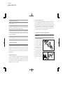
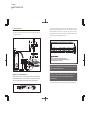
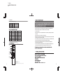
2 colors
PANTONE BLACK M
PANTONE 400 M
USER MANUAL
COVE LIGHT 12 SMD RGB
STRIP 12 SMD RGB
Please check for the latest updates and changes on the TRAXON website.
© TRAXON TECHNOLOGIES ALL RIGHTS RESERVED.
WWW.TRAXONTECHNOLOGIES.COM
HONG KONG
NEW YORK
PARIS
TOKYO
RIO DE JANEIRO
FRANKFURT
MELBOURNE
SHANGHAI
BIRMINGHAM
ROTTERDAM
Smart Chip - Version 1.2 Manual - Version 1.2
1 colors
PANTONE BLACK M
USER MANUAL
1. INTRODUCTION: P1
2. CONTENTS: P2
3. SAFETY AND OPERATION: P2-3
4. PRODUCT DESCRIPTION: P3-4
5. INSTALLATION AND SYSTEM CONFIGRATION: P4-9
5-1 MOUNTING: P4-5
5-2 DATA CONNECTION: P5-6
5-3 POWER CONNECTION: P7-8
5-4 CONTROL: P9
6. CARE AND MAINTENANCE: P10
7. TECHNICAL SPECIFICATION: P10
8. WARNING LABEL: P11
9. WARRANTY STATEMENT: P.11
1 colors
PANTONE BLACK M
FOR YOUR OWN SAFETY AND THAT OF THE PRODUCT, PLEASE READ THIS
USER MANUAL CAREFULLY BEFORE BEGINNING SET-UP AND INSTALLATION!
2. CONTENTS
COVE LIGHT 12 SMD RGB (MO-CL-52701, MO-CL-22701, MO-CL-02701)
1. INTRODUCTION
COVE LIGHT 12 SMD RGB (1PXL/DMX) MO-CL-52701
STRIP 12 SMD RGB (1PXL/DMX) MO-ST-50101
COVE LIGHT 12 SMD RGB (1PXL/RF) MO-CL-22701
STRIP 12 SMD RGB (1PXL/RF ) MO-ST-20101
COVE LIGHT12 SMD RGB (1PXL/SLAVE) MO-CL-02701
STRIP 12 SMD RGB (1PXL/SLAVE) MO-ST-00101
1 X Cove Light 12 SMD RGB
1 X DC Power Cable
1 X 3mm Hex Key
1 X RJ45 Data Cable
2 X M3 Screw
STRIP 12 SMD RGB (MO-ST-50101, MO-ST-20101, MO-ST-00101)
These products are part of the Traxon™ Modules product line, enabling the use of RGB LED
color changing systems in a linear configuration. On-board SMART CHIP™ technology (used in
the DMX Versions) with the powerful feature of Auto-Addressing enables fast and easy setup
and installation. High power LED technology combined with low power consumption brings the
best solution possible for any number of applications.
COVE LIGHT 12 SMD RGB
1 X DC Power Cable
2 X M3 Screw
1 X RJ45 Data Cable
2 x Nylon Spacer
1 X Strip 12 SMD RGB
3. SAFETY AND OPERATION
• 180° Position Adjustment
• 12 Ultra Bright SMD LED
(Laser apertures)
• DMX or RF Control Options
CAUTION – UNPLUG THE POWER SUPPLY FROM MAINS POWER BEFORE
CONNECTING ANY CABLES AS THIS CAN DAMAGE THE PRODUCTS !
• Auto-Addressing ( DMX Version Only )
• SMART CHIP™ ( DMX Version Only )
• RJ45 Cat5 Data Cabling
CAUTION – AVOID LOOKING DIRECTLY INTO THE LED LIGHT SOURCE AT CLOSE
RANGE FOR YOUR OWN SAFETY.
STRIP 12 SMD RGB
• 12 Ultra Bright SMD LED
ANY PERSON INSTALLING THIS PRODUCT SHOULD COMPLY WITH LOCAL
• DMX or RF Control Options
STANDARDS AND REGULATIONS AND MUST BE QUALIFIED FOR THE
• Auto-Addressing ( DMX Version Only )
HANDLING OF ELECTRICAL EQUIPMENT.
• SMART CHIP™ ( DMX Version Only )
• RJ45 Cat5 Data Cabling
1
(Laser apertures)
2
1 colors
PANTONE BLACK M
This product is designed for indoor use only
An ambient operating air temperature range of 0°C~+50°C (+32°F ~ +122°F) must be
adhered to at all times
If the fixture has been subjected to drastic temperature variances, e.g. following
transportation, do not connect the fixture until it has reached room temperature, as
internal condensation build-up may damage the fixtures' electronics.
When installing the fixtures and system power supplies in the chosen locations, please
ensure that they will not be exposed to moisture, extreme heat or direct sunlight and that it
is in a dirt and dust free environment keeping the fixtures and system power supplies
within their operating boundaries.
Please study all functions in this User Manual throughly and check the latest Technical
Specifications Sheets available from our website [www.traxontechnologies.com] before set-up.
• MASTER – SLAVE (DMX & RF Versions)
‘COVE LIGHT 12 SMD RGB DMX’ , ‘COVE LIGHT 12 SMD RGB RF’ and ‘STRIP 12 SMD RGB
DMX’ , ‘STRIP 12 SMD RGB RF’ are all referred to as being MASTER fixtures with control via
DMX512 with SMART CHIP™ technology or via RF remote control depending on the model
chosen. Using them together with the SLAVE versions ‘COVE LIGHT 12 SMD RGB SLAVE’ or
‘STRIP 12 SMD RGB SLAVE’ , the MASTER-SLAVE control relationship is utilized for
simultaneous color change of all fixtures, with only the MASTER receiving the control signal and
then sending the same signal to the other fixtures in the daisy-chain.
5. INSTALLATION AND SYSTEM CONFIGURATION
5-1 MOUNTING
5-1.1 COVE LIGHT 12 SMD RGB
FIG 1
For installation, use the M3
4. PRODUCT DESCRIPTION
91m
m/
screws provided for mounting to a
3.5
8”
flat surface (FIG 1). Select the
desired position and fasten the
screws in place, taking care not
and features include low power consumption, high light output with a wide even beam angle
to fix too tightly, but enough to
and an option of DMX512 with SMART CHIP™ technology or RF remote control. The SMART
hold the Cove Light firmly in
CHIP™ is a world first technology that includes the powerful feature of DMX auto
place. On the Cove Light base,
start-addressing and channel selection for the programmable 'Cove Light 12 SMD RGB' and
you will find a hex screw for fixing
'Strip 12 SMD RGB'.
the beam angle (FIG 2 & 3). When
using the provided 3mm Hex Key,
• MASTER – MASTER (DMX Versions)
take care not to fix too tightly as
'COVE LIGHT 12 SMD RGB DMX' and 'STRIP 12 SMD RGB DMX' are referred to as MASTER
overtightening can damage the
fixtures with control via DMX512 with SMART CHIP™ technology. Once the primary MASTER
fixture.
has been selected, subsequent MASTER models can be added with individual control via DMX.
M3 Screw
FIG 2
FIG 3
Swivel lamp body
180˚
51.5mm / 2.03”
The 'Cove Light 12 SMD RGB' and 'Strip 12 SMD RGB' are part of the MODULES product line
71mm / 2.80”
USE HEX KEY PROVIDED
TO LOCK THE HINGE
DO NOT FIX TOO TIGHTLY
The on-board SMART CHIP™ automatically assigns DMX start-addresses to all connected
MASTER fixtures upon powering up of the system.
3
4
1 colors
PANTONE BLACK M
5-1.2 STRIP 12 SMD RGB
FIG 4
For installation, first place the nylon
FIG 6
Nylon spacer
14
2.6
spacers provided into the mounting
mm
/5
.6”
holes on the bottom side of the Strip,
then use the M3 screws to mount to a
DMX 512 CONTROLLER
M3 screw
flat surface. Select the desired position
and fasten the screws in place, taking
• MASTER-SLAVE DATA CONNECTION
care not to fix too tightly, but enough
For MASTER-SLAVE data connections, a maximum of 99 SLAVE fixtures can be connected to 1
to hold it firmly in place (FIG 4).
MASTER fixture in a daisy-chain configuration (FIG 7).
5-2 DATA CONNECTION
FIG 7
Data connection is via the RJ45 sockets on the fixtures and the RJ 45 CAT5 patch cable that is
supplied with each fixture. For connection as per the diagram, follow the ‘DATA IN’ and ‘DATA OUT’
marking on the bottom of the fixture and firmly connect the cables in a daisy-chain configuration (FIG 5).
DMX 512 CONTROLLER
FIG 5
DATA OUT
DATA IN
• DMX512 CONTROLLER (A) / RJ45 INTERCONNECTION CABLE (B) - PIN OUT CONFIGURATION
(A)
(B)
IMPORTANT NOTE – DATA CONNECTION:
PLEASE BE SURE TO FOLLOW THE ‘DATA IN’ AND ‘DATA OUT’ MARKINGS WHEN
INTERCONNECTING TWO FIXTURES AS FAILURE TO DO SO WILL RESULT IN THE PRODUCT
NOT WORKING AND COULD CAUSE DAMAGE TO THE FIXTURES VOIDING THE WARRANTY
• MASTER-MASTER DATA CONNECTION
For MASTER-MASTER data connection, a maximum of 170 MASTER fixtures can be connected
together in a daisy-chain configuration. The on-board SMART CHIP™ technology is used to
automatically assign the DMX start-addresses once all data connections are made and when
powering up the system power supply/supplies (FIG 6).
CAUTION – THE DMX DATA INPUT CONNECTOR PIN ASSIGNMENT MUST
MATCH THE ABOVE DETAILS. FAILURE TO DO SO WILL RESULT IN THE
PRODUCT NOT WORKING AND COULD CAUSE DAMAGE TO THE FIXTURES
VOIDING THE WARRANTY.
5
6
1 colors
PANTONE BLACK M
5-3 POWER CONNECTION
For the DC power connection a maximum of 8 ‘COVE LIGHT 12 SMD RGB’ and/or ‘STRIP 12 SMD
The 'Cove Light 12 SMD RGB' and 'Strip 12 SMD RGB' range use an external 24V DC system
power supply. For connection of the mains AC input cable with the 24V DC output, please refer
to the diagram below (FIG 8).
RGB’ can be connected per dasiy-chain. Maximum 24 ‘COVE LIGHT 12 SMD RGB’ and/or ‘STRIP 12
SMD RGB’ are allowed to be connected to any 1 System Power Supply (320W) at a time. The DC
cable spam should not exceed 15m, starting from the System Power Supply connection terminals to
the last fixture in the chain. Please refer diagram below (FIG 10).
FIG 8
FIG 10
(4A FUSE)
NOTE:
1) MAX. 8 COVE LIGHTS CAN BE CONNECTED IN ONE DAISY CHAIN
2) MAX. 24 COVE LIGHTS CAN BE CONNECTED TO ONE POWER SUPPLY (320W)
3) MAX. POWER CONSUMPTION = 9W/UNIT AT 24V
CAUTION – PLEASE ENSURE THAT THE POWER IS SWITCHED OFF WHEN THE
DATA CABLES ARE BEING CONNECTED
AL-PS-00009
IMPORTANT NOTE – DC POWER CONNECTION:
FOR SAFETY, THE SYSTEM POWER SUPPLY SHOULD BE PLACED IN A
PLEASE BE SURE TO FOLLOW THE ‘POWER IN’ AND ‘POWER OUT’ MARKINGS WHEN
CONNECTING AS FAILURE TO DO SO WILL RESULT IN THE PRODUCT NOT WORKING
AND COULD CAUSE DAMAGE TO THE FIXTURES VOIDING THE WARRANTY(FIG 9).
USER RESTRICTED ACCESS AREA AND ACCESSED BY CERTIFIED
FIG 9
The socket-outlet should be installed near the equipment and should be easily accessible by installer.
POWER OUT
7
INSTALLERS ONLY.
POWER IN
8
1 colors
PANTONE BLACK M
5-4 CONTROL
• DMX 512 ( DMX Versions only )
DMX VALUE 0-255
DMX VALUE 0-255
DMX VALUE 0-255
CHANNEL 1
CHANNEL 2
CHANNEL 3
RF Versions only
- Make sure that the power is swtiched off before installation and/or maintenance
- Make sure that the products are installed correctly and securely
- For indoor use only
- Keep products in a dry and precipitation free area as this may damage the products’
electronics
- Keep products in a dirt and dust free environment
- Make sure the products are not exposed to extreme heat and that they have sufficient
airflow and cool air circulation if required
- Do not attempt to service or repair the products unless done by an authorized service
personnel. Contact the local Traxon office or distributor for details
- Do not drop, knock or shake the products as rough handling may damage the
electronics and void the warranty
- Do not use harsh chemicals, cleaning solvents or strong detergents to clean. Wipe with a
damp cloth on housings and a dry cloth on electronics to remove dirt or dust
Red Light
Green Light
Blue Light
Speed
Color Mode
Sequence Modes
Function Modes
Memory Button
Pause Mode
Turn on/off the light
Sequence Modes:
Chill (S1), Motion (S2), Action (S3)
9
Function Modes:
Random (F1), Fusion (F2), Pulse (F3), Rave (F4), Ray (F5), Moments (F6)
10
1 colors
PANTONE BLACK M
As with all electronic devices, LED output degrades over time - a term called lumen depreciation.
This also explains why it is nearly impossible to expect photometric performances of two LED
products with different service life spans to be the same. The rate of LED degrade is a complicate
function of many factors such as operating efficiency, duration of continuous operation, and more
significantly environmental conditions (ambient temperature for example).
commonly found in semiconductor industry. To improve consistency in performance across the same
product. LED manufacturers “sort” LEDs into bins according to different preset parameters, such as
forward driving voltage, illumination, etc. Whereas binning is a sorting function, it is not a correction
process. Inherent variability in the manufacturing process results always in different binning
distributions according to different production lots. Traxon uses automatically binned LEDs on its
products, thereby minimizing output variations within the model range.
8. WARNING LABEL
COVE LIGHT 12 SMD RGB / STRIP 12 SMD RGB
DATA
IN
LED RADIATION
DO NOT STARE INTO BEAM CLASS 2 LED PRODUCT
Maximum power dissipation of LED: 340mW
Emitted wavelength(s): 468-615nm
(IEC 60825-1:1993+corrigendum 1994+A2:2001
+corrigendum June 2002 + A1:2002)
POWER
OUT
POWER
IN
LED RADIATION
DO NOT STARE INTO BEAM CLASS 2 LED PRODUCT
Maximum power dissipation of LED: 340mW
Emitted wavelength(s): 468-615nm
(IEC 60825-1:1993+corrigendum 1994+A2:2001
+corrigendum June 2002 + A1:2002)
11
Traxon warrants its Products against material or workmanship defects for a period of one (1) year
from date of purchase, provided that the purchased items are used under the conditions stated in
this user manuals.
Because LEDs are semiconductor devices, their performances are subject to inherent variability
DATA
OUT
9. WARRANTY STATEMENT
Please refer to the Product Warranty section under www.traxontechnologies.com/terms for warranty
terms and conditions.