1
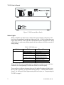
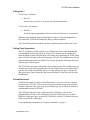
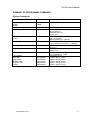
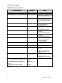
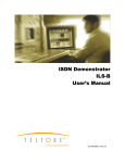
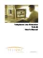
Telephone Line Simulator
TLS-3B
User’s Manual
40-400-00032, Rev. B
Note
This manual covers Model TLS-3B-01.
Copyright Notice
Copyright © 1995 - 2003 Teltone Corporation
All Rights Reserved
Trademarks
Teltone is a registered trademark of Teltone Corporation.
Windows is a registered trademark of Microsoft Corporation.
Other company and product names may be trademarks or
registered trademarks of their respective owners.
Teltone Corporation
Bothell, Washington 98021 USA
Customer Service: 425-951-3388
Technical Support: 425-951-3390
Fax: 425-487-2288
Email: [email protected]
Website: www.teltone.com
ii
40-400-00032, Rev. B
Table of Contents
Introduction..........................................................................................................1
TLS-3B Connectors and Lights ...........................................................................1
Status Lights.............................................................................................2
Line Jacks.................................................................................................3
Power Connector......................................................................................3
How to Install the TLS-3B...................................................................................3
Installing a Call Identifier ........................................................................4
How to Operate the TLS-3B ................................................................................4
Calling Line 2 ..........................................................................................4
Calling Line 1 ..........................................................................................5
Calling Party Supervision ........................................................................5
Forced Disconnect ...................................................................................5
Off-Hook Modes......................................................................................6
Caller ID...............................................................................................................6
Caller ID Date/Time ................................................................................6
Caller ID and Distinctive Ringing ...........................................................6
Compatibility with Caller ID Devices .....................................................6
Using Caller ID Prefixes..........................................................................7
Visual Message Waiting Indication .........................................................8
Programming the TLS-3B....................................................................................8
System Commands...................................................................................9
Individual Line Commands......................................................................11
Warranty and Service...........................................................................................14
Warranty Information ..............................................................................14
Return Procedures....................................................................................14
Technical Assistance................................................................................14
Specifications.......................................................................................................15
Summary of Programming Commands ...............................................................17
System Commands...................................................................................17
Individual Line Commands......................................................................18
40-400-00032, Rev. B
iii
IMPORTANT SAFETY INSTRUCTIONS
When using this product, basic safety precautions, including the following, should always be followed to reduce the risk of
fire, electric shock, and injury to persons.
1. Read and understand all instructions.
2. Follow all warnings and instructions marked on the product.
3. The product should be operated only from the type of power source indicated on the marking label. If you are not sure
of the type of power supply, consult your dealer or local power company. The product is designed for indoor use only.
4. To reduce the risk of electric shock, do not disassemble the product, but take it to qualified service personnel when
service or repair work is required. Opening or removing covers may expose you to dangerous voltages or other risks.
Incorrect reassembly can cause electric shock when the appliance is subsequently used.
5. If the product does not operate normally by following the operating instructions, or if the product has been dropped or
the cabinet has been damaged, or if the product exhibits a distinct change in performance, refer servicing to qualified
service personnel.
6. If the product is used in a manner other than specified in this manual, the protection provided by the product may be
impaired.
7. For the purpose of removing power from the product, the power input connector is the main power disconnect point.
Pull the power cord away from the connector to ensure power disconnect.
8. Adequate air flow must be maintained in order for the product to operate correctly. Do not wrap the product in
blankets, paper, or other material that may impede ventilation.
iv
40-400-00032, Rev. B
REGULATORY COMPLIANCE
FCC Part 15 Class A Notice: This equipment has been tested and found to comply with the limits for a Class A digital
device, pursuant to part 15 of the FCC Rules. These limits are designed to provide reasonable protection against harmful
interference when the equipment is operated in a commercial environment. This equipment generates, uses, and can
radiate radio frequency energy and, if not installed and used in accordance with the instruction manual, may cause
harmful interference to radio communications. Operation of this equipment in a residential area is likely to cause harmful
interference in which case the user will be required to correct the interference at his own expense.
40-400-00032, Rev. B
v
Telephone Line Simulator
TLS-3B
INTRODUCTION
The Teltone TLS-3B is a portable, two-line device that emulates the public telephone
network. The TLS-3B is a tool for demonstrating telephone instruments and other
telecommunications equipment, such as fax machines and modems. The TLS-3B’s
small size and light weight make it ideal for trade shows and other sales
presentations. It can also be used for testing telephone sets, key systems, and PBX
installations.
Like the public telephone network, but on a smaller scale, the TLS-3B can provide
dial tone, audible ring and busy signals to two telephones or other devices connected
to it. When a user picks up one phone (or other device) to dial up the second phone,
the TLS-3B sends ringing current to the second phone until it goes off-hook. The
TLS-3B then establishes a connection between the two phones. Either telephone can
then initiate a disconnect sequence by going on-hook.
Many of the TLS-3B’s features are programmable, including telephone numbers, offhook modes, signal delays, test tone frequencies, and line attenuation. The TLS-3B
also provides Caller Identification information to both lines, and lights a Visual
Message Waiting indicator.
In other words, the TLS-3B is a simple telephone network in a box. When a telephone
connection is not available, or when installing a temporary telephone line would be
costly, the TLS-3B provides all the signals and functions you will need to
demonstrate or test your telephones, modems, and other telecommunications
equipment.
TLS-3B CONNECTORS AND LIGHTS
The front panel of the TLS-3B has two telephone line jacks, with a green status
indicator light for each line, and a green Power indicator light. The power input
connector is on the rear panel. See Figure 1.
40-400-00032, Rev. B
1
TLS-3B User’s Manual
Figure 1. TLS Front and Rear Panels
Status Lights
When a telephone (or other device) connected to one of the Line connectors is off
hook, the corresponding Line indicator lights (see Table 1). The Line light dims (not
totally dark) when the TLS-3B decodes valid DTMF from the off-hook device. If the
off-hook device sends rotary dialing signals, the line indicator will flicker on and off
during dialing.
Table 1. LED Indicators
Indicator
Line 1/Line 2
State
On
Line is off-hook.
Flashing (fast on/off)
Blinking (slow on/off)
Line is ringing.
Programming mode: Line is
selected for programming.
During dialing, indicates that a
valid DTMF digit is present.
Caller ID is being sent to the
called phone number.
Setup 1
Setup 2
Half brightness
Dim blinking between rings
Power
Description
Single blink
Double blink
When the TLS-3B sends a ringing signal to a telephone attached to one of the Line
connectors, the corresponding Line indicator flickers on and off rapidly.
The green Power indicator alternates between full and half brightness (blink) when
the TLS-3B is operating. A single blink indicates Setup 1. A double blink indicates
Setup 2. For information about programming different setups, see “Programming the
TLS-3B” on page 8.
2
40-400-00032, Rev. B
TLS-3B User’s Manual
If the Power indicator is dark, no power is connected to the TLS-3B. If it lights, but
does not flicker, the TLS-3B’s internal processor is not working properly.
Line Jacks
Two Line connectors (RJ11 modular telephone jacks) are located on the front panel.
These connectors mate with the plugs on standard modular telephone cords.
Power Connector
The power connector requires a 24-volt DC power source. A 120-VAC 24-volt DC
power pack is supplied with the TLS-3B. Do not use the TLS-3B with a power pack
that supplies a different voltage. Use only with a Class 2 power supply!
HOW TO INSTALL THE TLS-3B
The TLS-3B works with analog loop start telephone sets only. It will not work with
ground start, proprietary, or digital phone sets.
Follow these steps to install the TLS-3B:
1. Plug the connector at the end of the power pack cable into the connector
on the rear panel of the TLS-3B.
2. Plug the power pack into a 120-volt AC wall outlet. The POWER
indicator will light.
3. Use a modular telephone cable to connect the telephones (or other devices
such as modems or fax machines) to the Line 1 and Line 2 connectors of
the TLS-3B.
4. Lift the handset of the telephone connected to Line 1. The Line 1 indicator
should light. Hang up and do the same thing for Line 2.
Warning: The TLS-3B generates a 100-volt ringing signal. Keep your hands
away from the plugs at the end of modular cables plugged into the TLS-3B
when the other line is off hook.
Caution: Do not try to connect the TLS-3B to the public telephone network.
Incoming ringing signals use voltages that can damage internal components in
the TLS-3B.
40-400-00032, Rev. B
3
TLS-3B User’s Manual
Installing a Call Identifier
To use the TLS-3B’s Caller ID feature, you must use an external call identifier or a
telephone set with built-in Caller ID. In most cases, the call identifier goes between
the TLS-3B and the telephone set. You should follow the instructions supplied with
the call identifier. If the call identifier instructions tell you to plug a cable into a wall
outlet, connect it to the TLS-3B.
HOW TO OPERATE THE TLS-3B
The TLS-3B has one talk path between the two lines. When a telephone connected to
either line goes off-hook while the other is still on-hook, the off-hook telephone
receives dial tone. If a telephone is already off-hook, the second telephone will not
receive dial tone (silence).
The TLS-3B stores two separate configurations, called Setup 1 and Setup 2. This
enables two different users to store settings they use often (for example, the sales staff
might use the TLS-3B in one setup, and engineering the other). When the unit is in
Setup 1, the Power LED blinks once; when it is in Setup 2, it blinks twice. For
information about programming different setups, see “Programming the TLS-3B” on
page 8.
Each line has two programmable telephone numbers. For programming information,
see “Programming the TLS-3B” on page 8. To call the other telephone, lift the
handset and dial one of the numbers assigned to the telephone you want to call. The
TLS-3B recognizes both rotary (pulse) and tone dialing.
The default telephone numbers for the two lines are:
Line 1 = 101 and 201
Line 2 = 102 and 202
Calling Line 2
To call Line 2 (Primary):
•
Dial 102.
One long ring (2 seconds on, 4 seconds off), repeated until answer.
To call Line 2 (Secondary):
•
Dial 202.
Two short rings (programmable): 800 mS on, 400 mS off, 800 mS on, 4 seconds off
4
40-400-00032, Rev. B
TLS-3B User’s Manual
Calling Line 1
To call Line 1 (Primary):
•
Dial 101.
One long ring (2 seconds on, 4 seconds off), repeated until answer.
To call Line 1 (Secondary):
•
Dial 201.
Two short rings (programmable): 800 mS on, 400 mS off, 800 mS on, 4 seconds off
When the other telephone rings, lift the handset to answer. The two telephones are
now connected. To break the connection, hang up either telephone.
The Caller ID transmission sends the primary telephone number of the caller’s line.
Calling Party Supervision
The U.S. telephone network typically uses Calling Party Supervision, meaning that
even though the called party hangs up, he may be reconnected to the calling party
when the phone is taken off-hook again. The calling party must hang up for the called
party to be fully disconnected before initiating a new call. The telephone network will
timeout and disconnect the call within 5-20 seconds, giving the called party dial tone
when he goes off-hook again.
The TLS-3B also provides Calling Party Answer Supervision. If the called party goes
on-hook and comes off-hook again before the forced disconnect or disconnect tone is
sent, the call will be reestablished. However, if the calling party goes on-hook and
then goes back off-hook again after the forced disconnect is sent, the call will not be
reestablished.
Forced Disconnect
Cutoff On Disconnect (COD) or Forced Disconnect, as it is also called, is a feature
provided by the TLS-3B. COD is a break in loop current that is sent to the off-hook
telephone when the other party goes on-hook (hangs up). The COD pulse duration is
programmable (default is 850 ms).
The COD delay (the time from on-hook until the COD pulse is sent) is also
programmable, but only for the calling party when the called party goes on-hook.
When the calling party goes on-hook, the COD delay is always 2 seconds before the
COD is issued to the called party.
For programming information, see “System Commands” on page 9.
40-400-00032, Rev. B
5
TLS-3B User’s Manual
Off-Hook Modes
The off-hook mode specifies what you hear when you lift the receiver on one of the
telephones connected to the TLS-3B. The three off-hook modes are Normal, which
provides dial tone; Ringdown, which causes the other telephone to ring; and Silence,
which connects the telephone to silence. The Normal mode is the default. For
programming information, see “Individual Line Commands” on page 11.
CALLER ID
The TLS-3B provides optional Caller ID (FSK) signaling on both lines. It supports
both Single Message Format (Date/Time/Number) and Multiple Message Format
(Date/Time/Number/Name). The Caller ID transmission is sent during the first long
silent interval after the first ringing cycle. A typical standard ringing period is
composed of a 2-second ringing cycle and a 4-second silent interval. Distinctive
ringing periods may be several short ringing cycles followed by at least a 3-second
silent interval. The TLS-3B is capable of many different types of ringing cycles and
silent periods (see “Programming the TLS-3B” on page 8), but a silence period of at
least 3 seconds is required in order to send a Caller ID message.
The display of the Caller ID information depends upon the type of equipment
connected to the TLS-3B, it may appear on the telephone itself, in the display of a
separate device, or on the video display of a personal computer.
Caller ID Date/Time
The TLS-3B issues a Date/Time value of 01/01 1:05 for the initial call after power is
applied. Subsequent calls will increment the time by 5 minutes. The Date/Time will
be reset back to the initial value of 01/01 1:05 if power is cycled on the TLS-3B.
Caller ID and Distinctive Ringing
Since there are circumstances such as privacy blockage, an out of area call, or a
transmission error, in which Caller ID is blocked, the TLS-3B can simulate these
events.
If you change the distinctive ringing cycles, remember that a 3-second silence is
required for the Caller ID information to be sent.
Compatibility with Caller ID Devices
Since there are a variety of Caller ID devices, the appearance of the information and
the amount displayed may differ slightly. For example, the format of the date and
time may be displayed differently.
6
40-400-00032, Rev. B
TLS-3B User’s Manual
Please note the following items when using Caller ID equipment:
•
Some Caller ID devices cannot display the calling name and, therefore,
do not accept the Multiple Message Format (default). If this is the
case with your device, use the Single Message Format instead.
•
Caller ID will be sent during the first 3-second silence in the ring
cycle. If you change the distinctive ringing cycles, remember that a 3second silence is required for the Caller ID information to be sent. (If
there is not at least a 3-second silence, Caller ID will not be sent).
•
Some Caller ID Devices require a 7-digit telephone number. If this is
the case with the device you are using, program the TLS-3B with 7digit numbers.
Using Caller ID Prefixes
Caller ID messages can be changed with one of three prefixes, entered before the
number you are dialing:
*67 = Private
*87 = Out of area call
*88 = Check sum error
For example, dialing *67 102 will ring Line 2 (assuming the default phone numbers
are used) and change the Caller ID message to a private message.
Dialing *87 102 will change the Caller ID message to an “out of area” call. The
Caller ID display will indicate that the call originated form an area in which Caller ID
is unavailable.
Note: Depending on the type of Caller ID display you are using, if private or
out-of-area feature is invoked, the date and time will be shown, but not the
number or name.
Dialing *88 102 will simulate a Caller ID checksum error. The Caller ID display will
indicate that an error occurred in Caller ID transmission.
Note: Caller ID displays react differently to a checksum error. Some attempt to
display the data, others display “line error”, and others ignore the data. Also,
some Caller ID displays require a 7- or 10-digit number. If this is the case with
the device you are using, program the TLS-3B with 7- or 10-digit numbers as
required.
40-400-00032, Rev. B
7
TLS-3B User’s Manual
Visual Message Waiting Indication
VMWI (Visual Message Waiting Indication) is a FSK signal issued by the Central
Office when a customer has a recorded voice message waiting to be retrieved. This
FSK burst is an on-hook signal that is sent after an OSI (Open Switching Interval),
which is a period of silence after some action. The TLS-3B can be used to simulate
the VMWI signal by going off-hook on one of the lines and entering *50 to activate
VMWI or *51 to de-activate VMWI for the other line.
Note: Different manufacturers Caller ID equipment react differently to this
signal. See your equipment manual for details.
*50 = Activates VMWI
*51 = De-activates VMWI
PROGRAMMING THE TLS-3B
The TLS-3B has a long list of features and functions, which a user can configure from
a touchtone telephone connected to either line. The TLS-3B stores two separate
configurations in memory. This enables, for example, two separate groups (such as
Engineering and Sales) to set up and use the TLS-3B for their applications. When
programming and using Setup 1, the Power LED blinks once. When programming
and using Setup 2, the Power LED blinks twice.
All programming commands begin with an asterisk (*) and end with a pound sign (#).
You can cancel a command before it is complete, by entering an asterisk before the
final pound sign. In some cases, a second asterisk many be necessary to cancel the
command. The response from the TLS-3B is three short tones.
Many commands either enable or disable specific functions in the TLS-3B. In all of
these commands, 0 disables the function, and 1 enables it. For example, the command
*10#0# disables the hook-flash detect function. *10#1# enables the hook-flash detect
function.
Commands are broken into two types:
•
System Commands affect both lines.
•
Individual Line Commands affect only the line being programmed.
While programming a line, its LED blinks on and off at a slow rate indicating
programming mode.
8
40-400-00032, Rev. B
TLS-3B User’s Manual
Follow these steps to enter Programming Mode:
1. Lift the handset on one of the telephones.
2. When you hear dial tone, enter **99## for Setup 1 mode, or **98## for
Setup 2 mode.
You hear three short beeps verifying proper program mode access. The Power
LED blinks once for Setup 1 and twice for Setup 2.
When you enter a programming command correctly, you will hear three short tones
(confirmation beeps). If you enter an incorrect command, you will hear alternating
high and low tones (error beeps).
A summary of programming commands is provided on page 17.
System Commands
Programming Mode
To enter programming mode from Line 1 or Line 2:
Setup 1
**99##
Setup 2
**98##
Reset
This command resets all options to the factory defaults, both Setup 1 and Setup 2.
*00#0#*00#0#
Tone Following Disconnect
These commands define the type of tone a caller hears when the other line
disconnects:
Dial Tone
Busy Signal
Reorder Signal
Silence
*04#0# (default)
*04#1#
*04#2#
*04#3#
Forced Disconnect (COD) Duration
This command sets the time duration of the line break to the off-hook device. The
time specifies the number of 50 mS increments. The range is from 0 to 100 (100 = 5
seconds). For example, to set disconnect to 850 mS (default), use 17 X 50 = 850 mS).
*05#time#
40-400-00032, Rev. B
9
TLS-3B User’s Manual
Cut-off on Disconnect Delay
This command sets the amount of time after the called party hangs up until the calling
party is sent the forced disconnect signal (COD). The time specifies the number of
100 mS increments. The range is from 11 (1.1 seconds) to 200 (20 seconds) and the
factory default is 2 seconds, i.e., *06#20#.
*06#time#
Ringing Frequency
This command defines the frequency of the signal that the TLS-3B will use as a
"RING".
20 Hz
25 Hz
*07#0# (default)
*07#1#
Hook-flash Detect
When Hook-flash detect is active, the TLS-3B will detect a switchhook flash after the
other line has answered. The TLS-3B will return dial tone and allow the user to dial
test numbers or one of the port numbers.
Disable Hook-flash Detect
Enable Hook-flash detect
*10#0# (default)
*10#1#
Line Attenuation
This command defines the signal loss of the talk path from one line to the other. This
command also affects the level of the call progress signals, e.g. Dial Tone, Busy,
Reorder, and Ringback.
Set attenuation to 6 dB
Set attenuation to 16 dB
*09#0# (default)
*09#1#
Test Numbers
These commands define the test telephone numbers. The name of the tone indicates
the type of signal you will hear when you dial the number. Test numbers may be up to
16 digits long. Valid digits are 0-9.
Dial Tone
Default = 83781 (Test 1)
Busy Signal
Default = 83782 (Test 2)
Reorder Tone
Default = 83783 (Test 3)
Ringback Tone
Default = 83784 (Test 4)
Silence
Default = 83785 (Test 5)
10
*60#number#
*61#number#
*62#number#
*63#number#
*64#number#
40-400-00032, Rev. B
TLS-3B User’s Manual
Individual Line Commands
In order to enter one of these commands, you must first select either Line 1 or Line 2.
The individual line command will affect only the line selected. The default is Line 1.
Select Line 1
Select Line 2
*01#
*02#
Note: It does not matter which line you use to enter programming mode or
these programming codes.
Primary Telephone Number
This command sets the Primary Telephone Number (up to 16 digits) for the currently
selected line. Valid numbers are 0-9. The factory default primary number for Line 1
is 101 and for Line 2 is 102.
*11#number#
Secondary Telephone Number
This command sets the Secondary Telephone Number (up to 16 digits) for the
currently selected line. Valid numbers are 0-9. The factory default secondary
number for Line 1 is 201 and for Line 2 is 202.
*12#number#
Secondary Number Ring Cadence
When dialing the Secondary Telephone Number, the called telephone rings with a
distinctive ringing pattern. x specifies the ringing time in 100 mS increments (range
is 0-30, where 30 = 3 seconds), and y specifies silence in 100 mS increments (range is
0-63). The default cadence is 800 mS on, 400 mS off, 800 mS on, and 4000 mS off.
The factory default is *23#8#4#8#40#0#0# .
*23#x#y#x#y#x#y#
Dial tone Delay
This command specifies the amount of time after the currently selected line goes off
hook before the TLS-3B sends dial tone. The time variable sets the duration in 100
mS increments and the range is 0 to 511. The factory default is 100 mS , i.e. *20#1#.
*20#time#
40-400-00032, Rev. B
11
TLS-3B User’s Manual
Network Response Delay
This command specifies the amount of time from the last dialed digit until the TLS3B starts to send Ringback, Busy, or Reorder tone. The time variable sets the duration
in 100 mS increments and the range is 0 to 511. The factory default is 200 mS, i.e.
*21#2#.
*21#time#
Second Dial Tone Number
This command defines the telephone number (up to 16 digits) that instructs the
TLS-3B to issue a second dial tone. Valid numbers are 0-9. The factory default is
711.
*13#number#
Second Dial Tone Delay
This command specifies the amount of time from the last dialed digit of the Second
Dial Tone Number (see Second Dial Tone Number command) until the TLS-3B
returns a second dial tone. The time variable sets the duration in 100 mS increments
and the range is 0 to 255. The factory default is 500 mS , i.e. *22#5#.
*22#time#
Busy Signal
This command defines the response to a busy condition. If the other line is off-hook
when you dial its number, the TLS-3B will return an audible busy indication, which
may be either a busy signal or a reorder tone.
Busy Signal
Reorder Tone
*30#0# (default)
*30#1#
Non-Valid Number Signal
This command defines the non-valid number signal. When you dial a number that is
not programmed to ring the other line or reach a test tone, the TLS-3B returns an
audible non-valid number signal, which may be either a busy signal or a reorder tone.
Busy Signal
Reorder tone
12
*31#0#
*31#1# (default)
40-400-00032, Rev. B
TLS-3B User’s Manual
Off-Hook Mode
The off-hook mode specifies what you hear when you lift the receiver on one of the
telephones connected to the TLS-3B. The three off-hook modes are Normal, which
provides dial tone; Ringdown, which causes the other telephone to ring; and Silence,
which connects the telephone to silence. The Normal mode is the default. Use one of
these commands to set the Off-Hook Mode:
Normal (dial tone)
Ringdown
--Primary Ringing Cadence
--Secondary Ringing Cadence
Silence
*32#0# (default)
*32#1#
*32#2#
*32#3#
Caller ID Format
This command specifies the type of Caller ID/Visual Message Waiting Indicator
(VMWI) message format the currently selected line will use. This option is controlled
by the called line.
No Caller ID/VMWI
Single Message Format
Multiple Message Format
*50#0#
*50#1#
*50#2# (default)
Caller ID Names
This command selects the Caller ID name that the calling line will send. This option
is controlled by the calling line.
Line 1: Clinton Bob / Line 2: Reagan Rick
Line 1: Montana Jim / Line 2: Marino Jim
Line 1: Anderson Allen / Line 2: Jones Jennifer
Sequence through all names and numbers
40-400-00032, Rev. B
*51#0#
*51#1#
*51#2# (default)
*51#3#
13
TLS-3B User’s Manual
WARRANTY AND SERVICE
Warranty Information
Teltone warrants this product to be free from defects in material and workmanship for
a period of one year, given proper installation and usage. At its sole discretion,
Teltone will repair or replace free of charge any unit found to be defective during the
warranty period. Units found defective beyond the warranty period will be repaired or
replaced at a flat rate.
Return Procedures
If a unit is found to be defective, contact Teltone customer service to obtain a RMA
(Return Material Authorization) number and shipping instructions. When returning
units, provide the following information:
•
Unit model number, unit part number, and serial number (obtained from the
Unit ID label on the bottom of the unit).
•
Teltone RMA number
•
All available fault information
•
Complete shipping and billing address
•
Repair purchase order
Technical Assistance
For technical assistance on this product, call Teltone technical support at
425-951-3390 or send an email to [email protected].
14
40-400-00032, Rev. B
TLS-3B User’s Manual
SPECIFICATIONS
Signaling
Ring Frequency
20 or 25 Hz
Ring Wave Form
Rounded square wave
Dial Tone Delay
0 - 511 mS in 100 mS increments. Default = 100 mS
Network Response Delay
0 - 511 mS in 100 mS increments. Default = 200 mS
Line Attenuation
-6 or -16 dB
Call Progress Signals
Dial Tone
350 + 440 Hz continuous
Ringback
440 + 480 Hz follows ringing cadence
Busy
480 + 620 Hz 500 ms on/500 ms off
Reorder
480 + 620 Hz 250 ms on/250 ms off
Tone Output Level
-19 dBm nominal w/low attenuation
-24 dBm nominal w/high attenuation
Forced Disconnect Duration
850 mS ±25 ms
Line Impedance
900 Ω ±20%
Dialing Requirements
Rotary
8 - 12 pps
DTMF Tone On/Off
>40 ms
On/Off-Hook Detect
<6 mA = on-hook
>18 mA = off-hook
Off-Hook Loop Current
>25 mA with 400 Ω total loop resistance
On-Hook Detect
>400 mS (switchhook flash disabled)
>1100 mS (switchhook flash enabled)
Caller ID/VMWI
Operation is per guidelines set in Bellcore Document
TR-NWT-000030, Issue 2, Oct 92
Output Level
Low Attenuation
High Attenuation
-17 dBm +3/-4 dB
-28 dBm +3/-4 dB
Transmission Rate
1200 ±12 baud
Mark (Logic 1)
1200 Hz ±12 Hz
Space (Logic 0)
2200 Hz ±22 Hz
Visual Message Waiting Indicator (VMWI) will operate
as specified in Bellcore Document TR-NWT-001401,
Issue 1, Sept 93 and FSD 01-02-2000.
Electrical
Power Input
24 VDC nominal, 500 mA minimum
On hook Voltage
-42 VDC nominal
Ringing Voltage
≥ 50 VAC RMS @ 20 Hz, @ 3 REN
40-400-00032, Rev. B
15
TLS-3B User’s Manual
Physical Dimensions
Size
5.5 x 1.5 x 9.0 in
Weight
1 lb 5 oz
Environmental
Operating Temperature
0°C to +50°C @ 95% humidity, non-condensing
Storage Temperature
-20°C to +60°C long term
Regulatory Compliance
EMC
United States
16
FCC Part 15, Class A
40-400-00032, Rev. B
TLS-3B User’s Manual
SUMMARY OF PROGRAMMING COMMANDS
System Commands
Command Name
Command
Programming Mode
Setup 1
Setup 2
Reset to Factory Defaults
Tone Following Disconnect
**99##
**98##
Forced Disconnect Duration
(COD)
*05#time#
Cutoff on Disconnect Delay
*06#time#
Ringing Frequency
*07#X#
Hook-flash Detect
*10#X#
Line Attenuation
*09#X#
Test Numbers
Dial Tone
Busy Signal
Reorder Tone
Ringback Tone
Silence
*60#number#
*61#number#
*62#number#
*63#number#
*64#number#
40-400-00032, Rev. B
*00#0#*00#0#
*04#X#
Notes
Dial Tone (default) X=0
Busy Signal X=1
Reorder Signal X=2
Silence X=3
Range = 0 to 100 in 50 mS steps
(100 = 5 seconds).
850 mS (default), i.e. *05#17#.
Range = 11 to 200 in 100 ms steps.
Factory default is 2 seconds, i.e. *06#20#.
20 Hz X = 0 (default)
25 Hz X = 1
Disable X = 0 (default)
Enable X = 1
X = 0 attenuation = -6 dB (default)
X = 1 attenuation = -16 dB
Valid digits are 0-9.
Default = 83781 (Test 1)
Default = 83782 (Test 2)
Default = 83783 (Test 3)
Default = 83784 (Test 4)
Default = 83785 (Test 5)
17
TLS-3B User’s Manual
Individual Line Commands
Command Name
Command
Select Line 1
Select Line 2
Primary Telephone Number
*01#
*02#
*11#number#
Secondary Telephone Number
*12#number#
Second Dial Tone Number
*13#number#
Dial Tone Delay
*20#time#
Network Response Delay
*21#time#
Second Dial Tone Delay
*22#time#
Secondary Number Ring Cadence
*23#x#y#x#y#x#y#
Busy Signal
*30#X#
Non-Valid Number Signal
*31#X#
Off-Hook Mode
*32#X#
Caller ID/VMWI Format
*50#X#
Caller ID Names
Line 1:Clinton Bob/Line 2:Reagan Rick
Line 1:Montana Jim/Line 2:Marino Don
Line 1:Anderson Allen/Line 2:Jones
Jennifer
Sequence through all names and
numbers
18
Notes
Range = 0-16 digits. Factory
default primary number for Line
1 is 101, and for Line 2 is 102.
Range = 0-16 digits. Factory
default secondary number for
Line 1 is 201, and for Line 2 is
202.
Range = 0-16 digits
Valid numbers are 0-9.
Factory default is 711.
Range = 0 to 511 in 100 mS
increments.
Factory default is 100 mS.
Range = 0-511 in 100 mS
increments.
Factory default is 200 mS.
Range = 0-255 in 100 mS
increments.
Factory default is 500 mS.
Default is 800 ms on, 400 ms
off, 800 ms on, and 4000 ms
off. Factory default is
*23#8#4#8#40#0#0# .
Busy Signal X = 0 (default)
Reorder Tone X = 1
Busy Signal X = 0
Reorder Tone (default) X = 1
Normal (dial tone) X = 0
(default)
Ringdown Primary # X = 1
Ringdown Secondary # X = 2
Silence X = 3
None X=0
Single Message Format X = 1
Multiple Message Format X=2
(default)
*51#0#
*51#1#
*52#2# (default)
*51#3#
40-400-00032, Rev. B