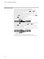
1
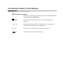
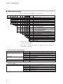
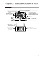
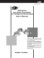
No. CP-SP-1118E
TM
CMS Series
Gas Mass Flow Meter
(For Hydrogen and Helium Gases)
User's Manual
Thank you for purchasing the CMS
Series Gas Mass Flow Meter for hydrogen and helium gases.
This manual contains information for
ensuring correct use of the CMS Series.
It also provides necessary information
for installation, maintenance, and troubleshooting.
This manual should be read by those
who design and maintain devices that
use the CMS Series.
Be sure to keep this manual nearby for
handy reference.
RESTRICTIONS ON USE
This product has been designed, developed and manufactured for general-purpose
application in machinery and equipment.
Accordingly, when used in applications outlined below, special care should be taken to
implement a fail-safe and/or redundant design concept as well as a periodic
maintenance program.
• Safety devices for plant worker protection
• Start/stop control devices for transportation and material handling machines
• Aeronautical/aerospace machines
• Control devices for nuclear reactors
Never use this product in applications where human safety may be put at risk.
NOTICE
Be sure that the user receives this manual before the product is used.
Copying or duplicating this user’s manual in part or in whole is forbidden. The information and specifications in this manual are subject to
change without notice.
Considerable effort has been made to ensure that this manual is free
from inaccuracies and omissions. If you should find an error or omission, please contact Yamatake Corporation.
In no event is Yamatake Corporation liable to anyone for any indirect,
special or consequential damages as a result of using this product.
©2005 Yamatake Corporation ALL RIGHTS RESERVED
The µF logo,Micro Flow are trademark of Yamatake Corporation in Japan.
SAFETY PRECAUTIONS
■ About Icons
The safety precautions described in this manual are indicated by various icons.
Please be sure you read and understand the icons and their meanings described
below before reading the rest of the manual.
Safety precautions are intended to ensure the safe and correct use of this product, to prevent injury to the operator and others, and to prevent damage to property. Be sure to observe these safety precautions.
WARNING
Warnings are indicated when mishandling this
product might result in death or serious injury.
CAUTION
Cautions are indicated when mishandling this
product might result in minor injury to the user, or
only physical damage to the product.
■ Examples
Use caution when handling the product.
The indicated action is prohibited.
Be sure to follow the indicated instructions.
i
WARNING
Never allow gases that are within explosive limits (in particular, mixed
gases within explosive limits that contain hydrogen) to pass through
this meter or device.
Doing so might result in explosion accidents.
When using this device for gases that contain hydrogen, be sure to
purge the device with an inert gas (nitrogen, argon, etc.) before use.
Use without purging the device with an inert gas might cause an
explosion and accident.Turn off power before purge, failure to do so
might result in the indication of "Err1".
CAUTION
Be sure to use this product within the flowrate range stated in the
specifications. To prevent excessive flow, use a suitable means to
control the supply pressure or use a throttle valve or the like to control
the flowrate. If the flowrate exceeds the upper limit, both the flowrate
display and the output voltage/current may indicate considerably lower
values than the actual flowrate.
If damage could result from the abnormal functioning of this device,
include appropriate redundancy in the system design.
Prevent foreign matter from entering the device.
If the rust, water droplet, oil mist or dust in the piping flows into the
device, measurement error might occur and result in damaging the
device.
If there is a possibility that any foreign matter flows into the device,
provide a filter, strainer or mist trap capable of eliminating more than
1µm foreign matter at the upstream, and periodically inspect and
replace the filter.
This device is exclusively for hydrogen and helium gases. It cannot be
used for measurement of gases other than hydrogen and helium, and
mixtures of these gases (excluding mixtures within explosive limits).
Oxygen cannot be measured even if gas-contacting sections on this
device are oil-inhibited.
This device is set initially for hydrogen gas use before shipment from
the factory. When using it for helium gas or mixed gases, the user must
change the gas type setting.
Use of this device for helium gas or mixed gases without changing the
gas type setting might result in an error.
Do not use this device outside of the operating pressure range. Also,
do not subject this device to a pressure above the pressure resistance.
Doing so might damage this device.
ii
CAUTION
When connecting piping, fasten the hexagonal section of the joint, and
turn the pipe side to connect.
After connecting the piping, check for any gas leaks.
Before connecting pipes on Swagelok connection method and VCR
connection method, check the precautions in the instruction manual
provided by the connecting joint manufacturer.
When purchasing a separate connecting joint, use the following made
by corresponding connection joint maker.
1/4Swagelok : Swagelok Co.,Ltd.
SS-400-1-6STSC11
1/2Swagelok : Swagelok Co.,Ltd.
SS-810-1-8STSC11
1/4VCR : Swagelok Co.,Ltd. SS-4-VCR-1-00032SC11
3/8VCR : Swagelok Co.,Ltd. SS-8-VCR-1-8STSC11 or equivalent product.
In the case of 1/2Rc, 1/4Rc connections, take care not to coat with too
much sealant. Dirt or burrs in the piping may also cause errors.
This device is a precision instrument. Do not drop it nor subject it to
shock. Doing so might damage the device.
When using a relay as the contact for integrated count reset input, use
a relay (gold contact type) for trace currents.
Otherwise, defective contact may cause the device to malfunction.
Be sure to check that the wiring is correct before turning the power ON.
Incorrect wiring might cause damage or malfunction.
If there is a risk of a power surge caused by lightning, use Yamatake
Corporation's SurgeNon to prevent possible fire or equipment failure.
When mounting the device, firmly fasten to prevent vibration.
Mount this device horizontally. If this device is mounted vertically , drift
will occur when flowrate is zero.
Do not mount so that the display is facing down.
Doing so might cause error or trouble.
Do not operate the keys with a mechanical pencil or sharp-tipped
object. Doing so might cause faulty operation.
Do not hold a resin cover portion at the time of carrying or piping this
device.
Doing so might damage the cover, or dropping the device due to
slipping might result in getting hurt.
Make sure that the selected analog output type matches the input type
of the receiving device. The output-receiving device could be damaged
if the analog output type selection is incorrect.
iii
Contents
SAFETY PRECAUTIONS
Conventions Used in This Manual
Chapter 1.
INTRODUCTION
■ Introduction • • • • • • • • • • • • • • • • • • • • • • • • • • • • • • • • • • • • • • • • • • • • • • • • • • • • • • • • • • • • • • 1
■ Features • • • • • • • • • • • • • • • • • • • • • • • • • • • • • • • • • • • • • • • • • • • • • • • • • • • • • • • • • • • • • • • • • 1
■ Model selection guide • • • • • • • • • • • • • • • • • • • • • • • • • • • • • • • • • • • • • • • • • • • • • • • • • • • • 2
Chapter 2.
NAMES AND FUNCTIONS OF PARTS
Chapter 3.
MOUNTING AND WIRING
■ Mounting • • • • • • • • • • • • • • • • • • • • • • • • • • • • • • • • • • • • • • • • • • • • • • • • • • • • • • • • • • • • • • • • 5
■ Behavior when the flowrate greatly exceeds
the upper limit of flowrate range • • • • • • • • • • • • • • • • • • • • • • • • • • • • • • • • • • • • • • • • 6
■ Piping • • • • • • • • • • • • • • • • • • • • • • • • • • • • • • • • • • • • • • • • • • • • • • • • • • • • • • • • • • • • • • • • • • • 6
■ Wiring • • • • • • • • • • • • • • • • • • • • • • • • • • • • • • • • • • • • • • • • • • • • • • • • • • • • • • • • • • • • • • • • • • 11
Chapter 4.
METHOD OF OPERATION
■
■
■
■
■
■
■
■
■
Chapter 5.
State transition diagram• • • • • • • • • • • • • • • • • • • • • • • • • • • • • • • • • • • • • • • • • • • • • • • • 14
Function setup • • • • • • • • • • • • • • • • • • • • • • • • • • • • • • • • • • • • • • • • • • • • • • • • • • • • • • • • • 15
Parameter setup • • • • • • • • • • • • • • • • • • • • • • • • • • • • • • • • • • • • • • • • • • • • • • • • • • • • • • • • 18
Display off mode • • • • • • • • • • • • • • • • • • • • • • • • • • • • • • • • • • • • • • • • • • • • • • • • • • • • • • • • 20
About integration and reverse-integration • • • • • • • • • • • • • • • • • • • • • • • • • • • • • • 21
Resetting the integrated value and reverse-integrated value • • • • • • • • • • • 21
What is "Event standby?" • • • • • • • • • • • • • • • • • • • • • • • • • • • • • • • • • • • • • • • • • • • • • • 21
Event ON delay • • • • • • • • • • • • • • • • • • • • • • • • • • • • • • • • • • • • • • • • • • • • • • • • • • • • • • • • • 21
Flowrate zero calibration • • • • • • • • • • • • • • • • • • • • • • • • • • • • • • • • • • • • • • • • • • • • • • • 22
TROUBLESHOOTING
■ Remedying trouble
Chapter 6.
• • • • • • • • • • • • • • • • • • • • • • • • • • • • • • • • • • • • • • • • • • • • • • • • • • • • •
23
SPECIFICATIONS
■ General specifications • • • • • • • • • • • • • • • • • • • • • • • • • • • • • • • • • • • • • • • • • • • • • • • • • • 24
■ External dimensions • • • • • • • • • • • • • • • • • • • • • • • • • • • • • • • • • • • • • • • • • • • • • • • • • • • • 28
■ Pressure loss • • • • • • • • • • • • • • • • • • • • • • • • • • • • • • • • • • • • • • • • • • • • • • • • • • • • • • • • • • • 33
iv
Conventions Used in This Manual
The following conventions are used in this manual:
Handling Precautions
: Handling Precautions indicate items that the user should pay attention
to when handling the CMS Series.
Note
: Notes indicate useful information that the user might benefit by
knowing.
(1), (2), (3)
: The numbers with the parenthesis indicate steps in a sequence or
indicate corresponding parts in an explanation.
03, P-07
: This indicates 7-segment indication on the setup display.
MODE
key
: This indicates a key on the setup display.
v
Chapter 1. INTRODUCTION
■ Introduction
The CMS Series Gas mass flow meter uses µF (Micro Flow) sensor in the
sensing section. The µF sensor is a thermal flow speed sensor made using
proprietary technology. Integrating this ultra-minute flow speed sensor with highgrade channel design technology has achieved high accuracy and high rangeability.
■ Features
• Incorporates a µF sensor made possible by silicon micro-machining technology
and thin-film forming technology.
One side of the µF sensor is a mere 1.7mm, and at a thickness of 0.5mm, this
thermal flow speed sensor exhibits high sensitivity and response.
• As the CMS Series are mass flow meter, it is not influenced by temperature nor
pressure.
• High accuracy of 5%RD* and high resolution
0.01L/min (standard)
(CMS0010)
0.1L/min (standard)
(CMS0050)
1L/min (standard)
(CMS0200/0500/1000)
5L/min (standard)
(CMS2000)
• The CMS Series are provided with extensive functions to suit a wide range of
applications: analog output, event output, integrating/reverse-integrating display,
output scaling, gas type selection, integrated pulse output, external contact input
(integrating reset input) and flowrate data serial output.
• Straight pipe sections are not required before and after this device.
Note
* "RD" (Reading) indicates the accuracy of the read value.
1
Chapter 1. INTRODUCTION
■ Model selection guide
The following shows the model Nos. for this flow meter:
Basic Flowrate Model
Connection Gas
Optional function Appended
Material
Output
model No. range type
method
type
1 2 3 4
No.
CMS
0010
0050
0200
0500
1000
2000
B
T
U
T
S
V
H
2
0
1
0
1
0
D
Y
0
Description
Gas Mass Flow Meter
Standard flowrate range 0 to 10L/min (standard) *1
Standard flowrate range 0 to 50L/min (standard) *1
Standard flowrate range 0 to 200L/min (standard) *1
Standard flowrate range 0 to 500L/min (standard) *1
Standard flowrate range 0 to 1000L/min (standard) *1
Standard flowrate range 0 to 2000L/min (standard) *1
Model with display
SUS316
9/16-18UNF(CMS0010/0050/0200)
3/4-16UNF(CMS0500/1000/2000)
Rc1/4(CMS0010/0050/0200)
Rc1/2(CMS0500/1000/2000)
1/4Swagelok(CMS0010/0050/0200)
1/2Swagelok(CMS0500/1000/2000)
1/4VCR(CMS0010/0050/0200)
3/8VCR or equivalent product(CMS0500/1000/2000)
Hydrogen, Helium *2
Analog output 0 to 5Vdc / 1 to 5 Vdc / 4 to 20mAdc
Without optional function
With RS-485 communications
Without optional function
Gas-contacting parts treated to be oil-inhibiting
Without options
Inspection Certificate provided
Complying with the traceability certification
Product version
*1 L/min (standard) indicates the volume flowrate (L/min) per minute converted
to 20˚C, one atmosphere.
*2 The gas type is initially set for hydrogen use. However, the user can change
this setting for helium use.
● Optical parts (sold separately)
Name
Harness with connector exclusive to CMS
Parts No.
81446594-005
Remarks
Harness (2m) for model without communications -- plain wire termination
(One harness is reguired for one CMS unit)
81446594-006
81446594-007
81446594-008
81446628-001
81446721-001
81446856-001
81446957-001
81446594-030
Harness (5m) for model without communications -- plain wire termination
Harness (2m) for model with communications -- M3.5 Y-terminals
Harness (5m) for model with communications -- M3.5 Y-terminals
For CMS0010/0050/0200
For CMS0500/1000
For CMS2000
Operating temperature range 0 to 40˚C
This harness is necessary for AC/DC adaptor.
Parts No.
81446834-001
81446834-002
81446833-001
81446833-002
81446895-001
81446895-002
Rc 1/4, a set of 2.
Rc 1/2, a set of 2.
1/4Swagelok, a set of 2.
1/2Swagelok, a set of 2.
1/4VCR, a set of 2.
3/8VCR, a set of 2.
Mounting bracket
AC/DC adaptor
Harness for AC/DC adaptor
● Spare parts
Name
Joint
2
Remarks
Chapter 2. NAMES AND FUNCTIONS OF PARTS
The following describes the names and functions of parts:
The diagram below shows CMS0500 model.
Instantaneous flowrate indicator lamp:
Lights when instantaneous flowrate
is displayed.
Integrated flowrate indicator lamp:
Lights when integrated
flowrate is displayed.
Massflow CMS
L/min
EV1
X10L
EV2
DISP
MODE
EV1, EV2 indicators:
Lights when event 1 and event 2 are output.
Flowrate display:
7-segment display indicates
flowrate by a 4-digit number.
The upper two digits on the display
indicate the function type, and the
lower two digits indicate the setup.
ENT
Display meter
key:
Used to switch
the display.
MODE key:
Used to select
the setup mode.
DISP
keys: Select the mode and
the mode setup.
ENT
key: Used to fix a mode setup.
Signal connector:
Connects the power supply
and output signals.
Pipe connection inlet:
The gas inflow is
connected here.
Pipe connection outlet:
The gas outflow is connected here.
3
Chapter 3. MOUNTING AND WIRING
WARNING
Never allow gases that are within explosive limits (in particular, mixed
gases within explosive limits that contain hydrogen) to pass through this
meter or device.
Doing so might result in explosion accidents.
When using this device for gases that contain hydrogen, be sure to purge the
device with an inert gas (nitrogen, argon, etc.) before use.
Use without purging the device with an inert gas might cause an explosion and
accident. Turn off power before purge, failure to do so might result in the
indication of "Err1".
CAUTION
Be sure to use this product within the flowrate range stated in the
specifications. To prevent excessive flow, use a suitable means to control
the supply pressure or use a throttle valve or the like to control the
flowrate. If the flowrate exceeds the upper limit, both the flowrate display
and the output voltage/current may indicate considerably lower values
than the actual flowrate.
If damage could result from the abnormal functioning of this device,
include appropriate redundancy in the system design.
Prevent foreign matter from entering the device.
If the rust, water droplet, oil mist or dust in the piping flows into the device,
measurement error might occur and result in damaging the device.
If there is a possibility that any foreign matter flows into the device, provide a
filter, strainer or mist trap capable of eliminating more than 1µm foreign
matter at the upstream, and periodically inspect and replace the filter.
This device is exclusively for hydrogen and helium gases. It cannot be used
for control and measurement of gases other than hydrogen and helium, and
mixtures of these gases (excluding mixtures within explosive limits).
Oxygen cannot be measured even if gas-contacting sections on this device
are oil-inhibited.
This device is set initially for hydrogen gas use before shipment from the
factory. When using it for helium gas or mixed gases, the user must change
the gas type setting.
Use of this device for helium gas or mixed gases without changing the gas
type setting might result in an error.
Do not use this device outside of the operating pressure range. Also, do not
subject this device to a pressure above the pressure resistance.
Doing so might damage this device.
When connecting piping, fasten the hexagonal section of the joint, and turn
the pipe side to connect.
After connecting the piping, check for any gas leaks.
When mounting the device, firmly fasten to prevent vibration.
In the case of 1/2Rc, 1/4Rc connections, take care not to coat with too much
sealant. Dirt or burrs in the piping may also cause errors.
4
Chapter 3. MOUNTING AND WIRING
CAUTION
Before connecting pipes on Swagelok connection method and VCR
connection method, check the precautions in the instruction manual provided
by the connecting joint manufacturer.
When purchasing a separate connecting joint, use the following made by
corresponding connection joint maker.
1/4Swagelok : Swagelok Co.,Ltd. SS-400-1-6STSC11
1/2Swagelok : Swagelok Co.,Ltd. SS-810-1-8STSC11
1/4VCR : Swagelok Co.,Ltd.
SS-4-VCR-1-00032SC11
3/8VCR : Swagelok Co.,Ltd.
SS-8-VCR-1-8STSC11 or equivalent product
This device is a precision instrument. Do not drop it nor subject it to
shock. Doing so might damage the device.
Do not hold a resin cover portion at the time of carrying or piping this
device.
Doing so might damage the cover, or dropping the device due to slipping
might result in getting hurt.
■ Mounting
● Installation site
Avoid mounting the CMS Series in the following locations:
• Locations whose operating temperature falls below -10˚C and rises above 60˚C
• Locations whose operating humidity exceeds 90%RH
• Locations subject to sudden changes in temperature and condensation
• Locations subject to corrosive gases and flammable gases
• Locations where there are lots of conductive substances (e.g. dust, salt or iron
dust), water droplets, oil mist or organic solvents
• Locations subject to vibration or shock
• Locations subject to direct sunlight
• Locations splashed by water or rain
• Locations subject to splashing by fluids (e.g. oil, chemicals.)
• Locations where strong magnetic or electrical fields are generated
5
Chapter 3. MOUNTING AND WIRING
■ Behavior when the flowrate greatly exceeds the upper limit of flowrate range
When the flowrate exceeds the upper limit of flowrate range, both the flowrate
display and the output voltage/current may indicate lower values than the actual
flowrate. Be sure to use this product within the flowrate range stated in the
specifications.
If the actual flowrate exceeds 120 % of the upper limit, both the flowrate display
and the output voltage/current will stop increasing in proportion to the flowrate.
If the flowrate is more than 200 % of the upper limit, both the flowrate display and
the output voltage/current will begin to decrease, giving the appearance that the
flowrate is within the flowrate range limits.
Also, if there is a sudden greatly excessive flowrate (200% of the upper limit or
more) for a very short period, the flowrate display and the output voltage/current
will continue to indicate flow within the flowrate range, without indicating the
spike.
Especially when this device is used for flow control, make sure to take appropriate
measures, such as controlling the supply pressure or using a throttle valve, so that
even at maximum control output, the flowrate does not exceed 120% of the upper
limit.
Flowrate display
& output voltage/
current
Flowrate range
100% 120%
Upper limit
200%
Actual flowrate
■ Piping
● Precautions for piping installation
This device is a precision instrument. If foreign matter such as dust, oil mist or
water enters the device, it may cause measurement error or faulty operation. When
installing piping, be sure to follow the procedures below to prevent foreign matter
from entering the device.
(1) Before installing the device, be sure to flush the upstream and downstream
piping thoroughly to remove welding fume particulate and dust.
(2) Be sure to wipe the inside of the pipe to be directly connected to this device.
(3) After the above two operations are complete, check to be sure that there is no
welding fume particulate or dust, and then install the device.
Handling Precautions
• If foreign matter cannot be fully eliminated by flushing or wiping, or if
the regular presence of foreign matter can be expected, be sure to
install a filter. If dust, oil or moisture adheres to the metallic mesh or
to the Micro Flow sensor chip, measurement error or device failure
may result.
Restrictor
Flow direction
µF sensor
Metallic mesh
Spacer
6
Chapter 3. MOUNTING AND WIRING
● Straight pipe section
In case of a different diameter pipe (A diameter is different from B diameter.),
straight pipe section may be required.
Upstream side enlarged
Downstream side reduced
5D
3D
CMS
A
CMS
B
Different diameter socket
Different diameter socket
5D
3D
CMS
A
A
B
CMS
B
A
B
Upstream side reduced
Downstream side enlarged
5D
3D
CMS
CMS
B
A
B
Different diameter socket
Different diameter socket
5D
3D
CMS
B
A
A
CMS
B
A
D indicates the connecting port size.
CMS0500/1000/2000: 12mm
CMS0010/0050/0200: 6mm
In case of a same diameter pipe (A and B diameters are same.), straight pipe
section may not be required.
Upstream side elbow
A
CMS
Downstream side elbow
A
CMS
B
B
Upstream side ball valve
(the valve having the structure
which does not disturb the gas flow)
CMS
A
B
Downstream side ball valve
(the valve having the structure
which does not disturb the gas flow)
CMS
B
A
Handling Precautions
Provide the 5D straight pipe section between the CMS and the butterfly
valve or the like in case of a valve having the structure which causes
disturbance or fluctuations to the gas flow.
7
Chapter 3. MOUNTING AND WIRING
● Rc Joint
• Coating sealant
Coat with an appropriate amount of sealant. Do not coat the top two threads of
the screw. Remove any dirt or burrs from inside the pipes.
Good example
Sealant
Bad example
Sealant
• Connecting Pipes
Connect pipes while gripping the Rc joint section of the pipe connection port
with a spanner or wrench.
Resin cover
Flange
Rc joint
Pipe
Body
Handling Precautions
• Do not grip and turn the body. Doing so might damage the body or
cause leakage.
• When connecting pipes, do not grasp the resin cover. Doing so might
damage the cover.
• Gas flow
Gas
Gas
Handling Precautions
When feeding gas into the meter, make it flow following the arrow on
the side of the channel. If gas is fed in the opposite direction, the gas
flow cannot be measured accurately.
8
Chapter 3. MOUNTING AND WIRING
● UNF Joint
• Connecting joint
Connect joint while gripping the flange section of the pipe connection port with a
spanner or wrench.
Resin cover
Flange
Joint
Body
Tightening torque
CMS0010 / 0050 / 0200 : 40 to 45 N m
CMS0500 / 1000 / 2000 : 50 to 60 N m
Handling Precautions
• Do not grip and turn the body. Doing so might damage the body or
cause leakage.
• When connecting pipes, do not grasp the resin cover. Doing so might
damage the cover.
• Keep the specified tightening torque.
• Gas flow
Gas
Gas
Handling Precautions
When feeding gas into the meter, make it flow following the arrow on
the side of the channel. If gas is fed in the opposite direction, the gas
flow cannot be measured accurately.
9
Chapter 3. MOUNTING AND WIRING
● Mounting the body
CAUTION
Mount this device horizontally. When this device is mounted vertically,
drift will occur when flowrate is zero.
Do not mount so that the display is facing down.
Doing so might cause error or trouble.
There are two ways of mounting the body of the CMS0010 / 0050 / 0200 / 0500 /
1000 / 2000:
(1)Fasten the body with the following screws from the rear side using the
mounting screws on the bottom of the device :
• CMS0010/0050/0200: two screws
• CMS0500/1000/2000: four screws
CMS0010/0050/0200
CMS0500/1000
5.5
4.5
30
27
15
unit:mm
CMS2000
4.5
48
48
80
(2) Attach the mounting bracket, and fasten the mounting bracket from the front
using four screws. Bracket part No. as follows:
• CMS0010/0050/0200: 81446628-001
• CMS0500/1000:
81446721-001
• CMS2000:
81446856-001
Unit: mm
•
Hole dimensions when mounting bracket is used
4.5
48
CMS0010/0050/0200
58
4.5
Mounting bracket
63
CMS0500/1000
78
5.5
75
CMS2000
80
Mounting Position
Massflow CMS
L/min
EV1
X10L
EV2
DISP
MODE
ENT
Handling Precautions
In case of vertical mounting, drift will occur when flowrate is
zero. For details, please contact Yamatake Corporation.
10
Chapter 3. MOUNTING AND WIRING
■ Wiring
CAUTION
When using a relay as the contact for integrated count reset input, use a
relay (gold contact type) for trace currents.
Otherwise, defective contact may cause the device to malfunction.
If there is a risk of a power surge caused by lightning, use Yamatake
Corporation's SurgeNon to prevent possible fire or equipment failure.
Be sure to check that the wiring is correct before turning the power ON.
Incorrect wiring might cause damage or malfunction.
We recommend using the harness (sold separately) with connector exclusive to CMS.
● Connector pin layout
The following shows the layout of the connector pins on this flow meter:
1
9
2
10
View from connector insertion side
Compatible connector:
DF11-10DS-2C made by HIROSE ELECTRIC CO., LTD.
Harness with connector exclusive to CMS:
See optional parts (page 2)
● Connector signal table
Pin
number
Signal
name
Description
1
DC OUT+ Instantaneous flowrate output +
2
3
4
DC OUTV+
GND
5
6
7
8
DA
DB
DI
EV2
9
10
Remarks
Instantaneous flowrate output Power + (12 to 24Vdc)
Power GND
For RS-485 communications
Do not connect for the model without
RS-485 communications.
Integration count reset input
Event 2 output/Integration pulse output
EV1
Event 1 output/Serial data output
EVCOM/SG Event output common /
RS-485 communications common
11
Chapter 3. MOUNTING AND WIRING
Connection example
1
DC OUT+ (Brown)
2
DC OUT- (Red)
3
V+ (Orange)
4
GND (Yellow)
5
DA (Pink)
6
DB (Blue)
7
Integration count reset input (green)
8
EV2
(Gray)
9
EV1
(White)
Instantaneous flowrate output
12 to 24Vdc
RS-485
communications
Installed externally
Load (30Vdc, 50mA max.)
Load
(30Vdc, 50mA max.)
10 EV COM /SG (Black)
Interal circuit
30Vdc
max.
External connection example
Handling Precautions
• Power source GND, instantaneous flow rate output (-), and event output common lines are all connected inside this device. If these lines
are connected to an external device through a common power supply,
interference will cause device failure or faulty operation.
• Take care that the event output does not exceed the output rating of
this device. If a relay is used, the coil should have a built-in surge
absorption diode. Otherwise device failure could occur.
12
Chapter 3. MOUNTING AND WIRING
● Connection of totalizer pulse output to a counter
• Non-voltage input type
8
EV2
10
EVCOM
Input
Counter
0V
• Voltage input type
Pull-up resistor
8
EV2
10
EVCOM
30Vdc or less
Input
Counter
0V
● When using flowrate data serial output
• Connection example
+5V
9
10
EV1
+5V
10k
10k
RS-232C driver
RXD
EV COM
GND
CMS
RTS
CTS
Computer
RS-232C port
Interface
• Communications protocol
Currently displayed instantaneous flowrate data and integrated flowrate data is
sent as ASCII code. Data is sent in order instantaneous flowrate data followed
by integrated flowrate data. Instantaneous flowrate data is prefixed with "F" and
integrated flowrate data is prefixed with "T".
Example: When instantaneous flowrate is 10.0L/min (standard), and integrated
flowrate is 100L.
" F 0 1 0 . 0 T 0 0 0 0 0 1 0 0 . " C R
100L
L F
0Dh 0Ah
Integrated flowrate
10.0 L/min(standard)
Instantaneous flowrate
• Communications specifications
Item
Description
Communications method
Conform to RS-232C, Start-stop transmission
Transmission speed
9600bps
Character length
8bits
Stop bit
2bit
Parity
None
Data transmission cycle
100 10ms
13
Chapter 4. METHOD OF OPERATION
CAUTION
Do not operate the keys with a mechanical pencil or sharp-tipped
object. Doing so might cause faulty operation.
Make sure that the selected analog output type matches the input type
of the receiving device. The output-receiving device could be damaged
if the analog output type selection is incorrect.
■ State transition diagram
In the factory setting, the instantaneous flowrate indicator lamp lights.
The following diagram shows the relationship between migration modes and
display:
If 020 1 or 0202 are set in the display mode setup, the integrated flowrate or
reverse-integrated flowrate is displayed by pressing the DISP key while the
instantaneous flowrate is displayed.
Pressing the DISP key again returns the display to the instantaneous flowrate
display.
When the power has been turned OFF then back ON again, the display state before
the power was turned OFF is held.
%
& ! "#$
! ' %
"#$
& ! "#$
%
& Handling Precautions
• Leave the device powered up for about 30 minuites befor use to allow it
to stabilize.
14
Chapter 4. METHOD OF OPERATION
■ Function setup
The following describes how to set up each of the functions.
• To enter the setup mode, press the MODE key.
The upper two digits on the display blink. The upper two digits on the display
indicate the function type, and the lower two digits indicate the setup.
• Pressing the
key moves the setup to the next item. Pressing the
key moves the setup item to the previous item.
Key lock setup
key
key
Display mode setup
key
key
Event 1 type setup
*1
key
Flow deadband setup
key
• Pressing the
key again when 12 *2 is displayed returns the display to 0 1.
Pressing the
key again when 0 1 is displayed changes the display to 12*2 .
• When the upper two digits are the setup item that you want to set, press the
ENT
key while it is blinking.
This selects the setup item, and the lower two digits blink.
• Press the
and
keys to select the desired setting value, and press
the ENT key.
All four digits light.
• Make sure that the items and the setups are correct.
• To continue setup, press the MODE key again and repeat the setup operation.
*1 : In case of the model with RS-485 communications, 30, 31 and 32 is displayed
after 12.
*2 : 32 is displayed for the model with RS-485 communicarions.
The following table shows the function and the setup:
15
Chapter 4. METHOD OF OPERATION
● Function setup menu
Mode
Function
01
Key lock
02
Display mode
Setting
00
01
00
01
02
03
Event 1 type
(EV1)
04
Event 2 type
(EV2)
05
ON delay setting
(EV1)
06
ON delay setting
(EV2)
07
Event standby
setting
00
01
02
03
04
05
06
00
01
02
03
04
05
06
07
00
01
00
01
00
01
Gas type selection
08
Description
Key lock disabled
Lock ON
factory
Remarks
setting
00 Other modes cannot be
entered in a key lock state.
Only instantaneous flowrate displayed
Instantaneous flowrate/integrated flowrate
displayed
Instantaneous flowrate/reverse integrated
flowrate displayed
01
Not used
Instantaneous flowrate upper limit value
Instantaneous flowrate lower limit value
Integrated flowrate count up
Reverse integrated flowrate count down
Flowrate data serial output
Error output
00
Not used
Instantaneous flowrate upper limit value
Instantaneous flowrate lower limit value
Integrated flowrate count up
Reverse integrated flowrate count down
Integration pulse output rate*1
Integration pulse output rate*1
Integration pulse output rate*1
00
Not used
Used
00
Displayed only when mode
03 is set to 01 or 02.
Not used
Used
00
Displayed only when mode
04 is set to 01 or 02.
Not used
Used
00
Conversion factor(CF) for each gas
type set by the user
Hydrogen
Helium
0G
When 08 is selected, set the
conversion factor (CF) in the
parameter setup mode.
*2
00
*3
0-5 Vdc
1-5 Vdc
4-20 mAdc
00
0-35˚C
(1˚C step)
20
101.325 kPa (atomospheric
pressure) reference
No deadband
Less than minimum display*
Less than 1%FS
Less than 2.5%FS
Less than 5%FS
01
When gas type 08 is selected,
setting value x CF
become the deadband.
CF refers to the compensation
coefficient according to gas
type, and its range is 0.10 to
8.00. * The minimum display
differs from models. For more
detail, see page 26.
The operation of integrating
count up, reverse-integrating
count down and integration
pulse output is effective only
when mode 02 is set to 0 1 or
02.
Also, integrating count up and
reverse-integrating count down
cannot be set simultaneously.
Displayed only when mode
03 or 04 is set to 02.
For more detail, see page 26.
08
0G
10
11
12
16
0G
10
Analog output
00 to
scaling
04
Analog output type
00
01
02
Flowrate conversion
00 to
reference temperature 35
Flow deadband
00
setting
01
02
03
04
Chapter 4. METHOD OF OPERATION
Item
Function
Setting
30
Communications
address
00
0 1 to
GG
31
Transmission
speed
32
Data format
Setting description
Factory
setting
Remarks
Communication function disabled
Communication address
00
For the model with
RS-485 communication only
00
01
02
9600bps
4800bps
2400bps
00
For the model with
RS-485 communication only
00
01
8 data bits, even parity, 1 stop bit
8 data bits, no parity, 2 stop bits
00
For the model with
RS-485 communication only
*1 Integration pluse output rate
mode
Setting
CMS0010/0050
CMS0200/0500/1000/2000
04
05
06
07
1L/pulse
10L/pulse
100L/pulse
10L/pluse
100L/pluse
1000L/pluse
*2 Analog output scaling
mode
setting
0G
00
01
02
03
04
CMS0010
Unit : L/min
CMS0050
CMS0200
0 to 10
0 to 50
0 to 200
0 to 5
0 to 30
0 to 100
0 to 2.5
0 to 20
0 to 50
0 to 1
0 to 10
0 to 20
flexible scaling flexible scaling flexible scaling
CMS0500
CMS1000
CMS2000
0 to 500
0 to 1000
0 to 2000
0 to 300
0 to 500
0 to 1000
0 to 200
0 to 250
0 to 500
0 to 100
0 to 100
0 to 200
flexible scaling flexible scaling flexible scaling
*3 When 08 is selected at the gas type, the scaling becomes the value multiplied by the conversion factor of each
scaling.
For example, when the scalling is set to 0 1 : 0 to 5(L/min) on the CMS0010, and the conversion factor is 0.5 ,
the analog output scaling becomes 0 to 2.5(L/min).
17
Chapter 4. METHOD OF OPERATION
■ Parameter setup
Cancel the function setup key lock setting (key lock disabled).
Set the setting value of function setup modes 03 and 04 to other than 00.
To enter the parameter setup mode, hold down the ENT and
keys
simultaneously for at least three seconds.
In the parameter setup mode, P-_ _ is displayed on the display. The lower two
digits on flowrate display indicate the parameter item.
Pressing the
key moves the setup to the next item. Pressing the
key moves the setup item to the previous item.
Press the ENT key at the item you want to set.
The current setting value is displayed.
If you press the ENT key again, the lowermost digit blinks.
MODE key
If you press the MODE key, the blinking cursor moves to the left. To change the
setting value at each of these digits, use the
and
keys.
Press the ENT key, the setting value is fixed.
When 03 or 04 has been set as the event type in the function setup, setup the 8digit display at P-0 1, 02 and 07.
To do this, switch between the upper 4-digit and lower 4-digit display as follows:
Lower four digits
key
Upper four digits
key
Decimal point display
The following table shows available parameters and setting values:
P-0 1 to P-G is displayed according to the setting values of the function setup.
18
Chapter 4. METHOD OF OPERATION
● CMS0010
Parameter
P-0 1
Item
Factory setting
0.00
00000000
0.00
00000000
0.50
0.50
0
0
00000000
Event 1 setting value
(EV1)
P-02
Event 2 setting value
(EV2)
P-03
P-04
P-05
P-06
P-07
P-08
EV1 hysteresis
EV2 hysteresis
EV1 ON delay
EV2 ON delay
Reverse-integrated
default
Gas type conversion
Setting range
0.00 to 99.99(L/min)
00000000 to 99999999(L)
0.00 to 99.99(L/min)
00000000 to 99999999(L)
0.00 to 1.00(L/min)
0.00 to 1.00(L/min)
0 to 60(s)
0 to 60(s)
00000000 to 99999999(L)
The conditions of display
(Setting mode of function)
when 03 is 0 1 or 02
when 03 is 03 or 04
when 04 is 0 1 or 02
when 04 is 03 or 04
when 03 is 0 1 or 02
when 04 is 0 1 or 02
when 03 is 0 1 or 02
when 04 is 0 1 or 02
when 02 is 02
1.000 0.100 to 8.000
when 08 is 08
100 10 to 250(%)
when 0G is 04
factor
P-0G
Analog output scaling
● CMS0050
Parameter
P-0 1
Item
Factory setting
0.0
00000000
0.0
00000000
5.0
5.0
0
0
00000000
Event 1 setting value
(EV1)
P-02
Event 2 setting value
(EV2)
P-03
P-04
P-05
P-06
P-07
P-08
EV1 hysteresis
EV2 hysteresis
EV1 ON delay
EV2 ON delay
Reverse-integrated
default
Gas type conversion
Setting range
0.0 to 999.9(L/min)
00000000 to 99999999(L)
0.0 to 999.9(L/min)
00000000 to 99999999(L)
0.0 to 10.0(L/min)
0.0 to 10.0(L/min)
0 to 60(s)
0 to 60(s)
00000000 to 99999999(L)
The conditions of display
(Setting mode of function)
when 03 is 0 1 or 02
when 03 is 03 or 04
when 04 is 0 1 or 02
when 04 is 03 or 04
when 03 is 0 1 or 02
when 04 is 0 1 or 02
when 03 is 0 1 or 02
when 04 is 0 1 or02
when 02 is 02
1.000 0.100 to 8.000
when 08 is 08
100 10 to 250(%)
when 0G is 04
factor
P-0G
Analog output scaling
● CMS0200/0500/1000/2000
Parameter
P-0 1
Item
Event 1 setting value
(EV1)
P-02
Event 2 setting value
(EV2)
P-03
P-04
P-05
P-06
P-07
P-08
EV1 hysteresis
EV2 hysteresis
EV1 ON delay
EV2 ON delay
Reverse-integrated
default
Gas type conversion
Factory setting
0.
00000000
0.
00000000
50. * 2
50. * 2
0
0
00000000
Setting range
0 to 9999(L/min) * 1
00000000 to 99999999(X10L)
0 to 9999(L/min) * 1
00000000 to 99999999(X10L)
0 to 100(L/min) * 2
0 to 100(L/min) * 2
0 to 60(s)
0 to 60(s)
00000000 to 99999999(X10L)
The conditions of display
(Setting mode of function)
when 03 is 0 1 or 02
when 03 is 03 or 04
when 04 is 0 1 or 02
when 04 is 03 or 04
when 03 is 0 1 or 02
when 04 is 0 1 or 02
when 03 is 0 1 or 02
when 04 is 0 1 or 02
when 02 is 02
1.000 0.100 to 8.000
when 08 is 08
100 10 to 250(%)
when 0G is 04
factor
P-0G
Analog output scaling
19
Chapter 4. METHOD OF OPERATION
Note
*1 In case of gas type 08 on the CMS0200;
and when P-08 (conversion factor) is set to 0.100 to 0.499, the range becomes
0.0 to 999.5 (in 0.5 intarvals). When the factor is set to 0.500 to 8.000, the
range becomes 0 to 9999.
However, use at a set point within setting range.
*2 In case of gas type 08 on the CMS0200;
and when P-08 (conversion factor) is set to 0.100 to 0.499, the factory setting
is 5.0 and the setting range becomes 0.0 to 10.0(in 0.5 increments intervals).
Handling Precautions
• Setting value must be in measuring range.
■ Display OFF mode
If the DISP key is held down for at least three seconds, all display is turned off
except for the instantaneous flow rate indicator lamp, which blinks.
■ About integration and reverse-integration
When the integrated value exceeds 99999999, it is changed to 0 and count up
continues. In this case, the event output of integrated flowrate count up is OFF
until again reaching the set point. When the reverse-integrated value is 0, the
count down stops.
■ Resetting the integrated value and reverse-integrated value
To reset the integrated/reverse-integrated value, hold down the
and
keys simultaneously for at least one second with the integrated/reverseintegrated value displayed.
The integrated value is reset to 0 and the reverse-integrated value is reset to the
default, and integration/reverse-integration is resumed.
20
Chapter 4. METHOD OF OPERATION
■ What is "Event standby?"
"Event standby" is enabled only on the instantaneous flowrate lower limit value.
This function prevents erroneous operation of the lower limit alarm when there is
no gas flowrate, for example, when the device is started up.
There is no event action until the instantaneous flowrate value once exceeds the
event lower limit setting value after the power is turned ON. Event action is
normal after the event lower limit setting value has been exceeded once.
Instantaneous flowrate value
Event action
Event
standby
Lower limit
setting value
Time
ON
OFF
Event output
■ Event ON delay
ON delay (0 to 60s) is set for each of events 1 and 2.
ON
Event output
ON delay
OFF
Instantaneous
flowrate value
Event ON
Time
Event detected
21
Chapter 4. METHOD OF OPERATION
■ Flowrate zero calibration
If the indicated flow rate is not zero even though the actual flow rate is zero, and it
seems possible that the sensor's zero point may have shifted, try the following procedure for flowrate zero calibration:
(1) Display the flowrate or integrated flowrate value.
(2) Press and hold the
ENT
key.
(3) After approx. 10 seconds have elapsed, 0. CAL blinks on the flowrate display.
(4) Press and hold
ENT
again.
(5) After approx. 1 second, 0. CAL stops blinking and remains lit. The amount of
sensor output at this moment is now treated as zero.
(6) Press DISP key to return to the instantaneous flowrate or integrated flowrate
display.
Handling Precautions
Use flowrate zero calibration only after ensuring that the flow path
contains only the gas being measured, and after stabilizing the actual
flow rate at zero.
22
Chapter 5. TROUBLESHOOTING
■ Remedying trouble
Refer to the following table if trouble occurs:
Phenomena
Countermeasure
Nothing on display
• Make sure that power of correct voltage and polarity is being supplied.
• Make sure that connectors are correctly connected.
ALH1 is displayed
The instantaneous flowrate value has exceeded 120% of the measurement
range.
Reduce the flowrate so that it is within the range, then nomal operation will
automatically resume.
Err 1 is displayed
Sensor error
• Make sure that gas is not flowing excessively, or the gas is not flowing
reversely.
• Make sure that the purging is not performed while power is supplied.
• The flowrate becomes within the range, mormal operation will automatically
resume. If the device does not resume normal operation, contact Yamatake
Corporation and ask for repair.
Err2 is displayed
Memory data error
Contact Yamatake Corporation and ask for repair.
Err3 is displayed
Heater current error of sensor.
After closing the gas valve, turning the power off and then on again. If the
device does not resume normal operation, contact Yamatake Corporation and
ask for repair.
Err4 is displayed
Sensor heater safty circuit worked.
After closing the gas valve, turning the power off and then on again. If the
device does not resume normal operation, contact Yamatake Corporation and
ask for repair.
Signal is output even
• Check the piping for any gas leaks.
though the flowrate should • Check the wiring to make sure that it is correct.
be "zero".
Flowrate deviates.
• Check the piping for any gas leaks.
• Check the piping and connection ports for dirt, oil or other foreign matter.
If oil is adhering to these parts, contact Yamatake Corporation.
• Check the wiring to make sure that it is correct.
• Check the flowrate to see that it does not deviate considerably within several
seconds, or that it does not greatly exceed the measurement range.
The displayed value is
lower than expected.
There should be no flow
but the indicated flow
rate is higher than zero.
• Check if the gas contains foreign matter such as dust, rust, oil or water.
If it seems that there is foreign matter in the flow meter, contact Yamatake
Corporation and ask for repair.
Integration is incremented
or reverse integration is
decremented even though
the instantaneous flowrate
indication is "zero".
• Check the piping for any gas leaks or check if gas flow stops.
There is a possibility that a small volume gas less than the minimum
display value is flowing even though the instantaneous flowrate indication
is zero.The flowrate less than the minimum indication value is counted in
the integration computation.
Set the flow deadband to remove the countup of integrated value (or
countdown of reverse-integrated value).
(■ See Function setup)
23
Chapter 6. SPECIFICATIONS
■ General specifications
Model No.
CMS0010
Item
CMS0050
CMS0200
Applicable gas
Hydrogen, Helium.
Gas must not contain corrosive components (chlorine, sulfur, acid, etc.).
Flow range *1
10L/min (standard)
50L/min (standard)
200L/min (standard)
standard indicates the calibration criteria (101.325kPa(1atm), 20˚C).
Measurement accuracy *2
101.325kPa, 23˚C conversion
(χ : measured flowlate)
0.1≤χ<2L/min
±1%FS±1digit
2≤χ≤10L/min
±5%RD±1digit
0.5≤χ<10L/min
±1%FS±1digit
10≤χ≤50L/min
±5%RD±1digit
Temperature characteristics *3
-10 to +60˚C
Flow range 0 to 75%
Flow range 75 to 100%
±0.10%FS/˚C±1digit
±0.15%FS/˚C±1digit
Pressure characteristics *4 Flow range 0 to 50%
±0.3%FS/0.1MPa±1digit max.
0 to 1.0MPa
Flow range 50 to 100% ±3%RD±1digit max.
Negative pressure characteristics
Flow range 0 to 50%
*4
2≤χ<40L/min
±1%FS±1digit
40≤χ≤200L/min
±5%RD±1digit
±0.1%FS/0.1MPa±1digit max.
±0.1%RD/0.1MPa±1digit max. ±0.5%RD/0.1MPa±1digit max.
±0.5%FS/0.01MPa±1digit max. ±0.2%FS/0.01MPa±1digit max. ±0.5%FS/0.01MPa±1digit max.
-0.07 to 0MPa Flow range 50 to 100% ±1%RD/0.01MPa±1digit max. ±0.5%RD/0.01MPa±1digit max. ±1%RD/0.01MPa±1digit max.
Operating pressure range
-0.07 to 1.0MPa
Pressure resistance
1.5MPa
Sampling cycle
100±10ms
Output signal
(instantaneous flowrate output)
0-5Vdc / 1-5Vdc
: Allowable load resistance 250kΩ min.
6Vdc max. even if flowrate exceeds range.
4-20mAdc
: Allowable load resistance 300Ω max.
24mAdc max. even if the flowrate exceeds range.
Event
Number of events
output
Output
Open collector (30Vdc, 50mA max.)
Integration pulse
output width
100ms±10%
Integration pulse
output rate
1, 10, 100 L/pulse
External
Number of input
1
input
Circuit type on other
side
No-voltage contact or open collector
Contact OFF
terminal voltage
4.5±1V
Contact ON
terminal current
approx. 0.5mA (current flowing to contact)
Allowable ON
contact resistance
250Ω max.
Allowable OFF
contact resistance
100kΩ min.
Allowable ON
residual voltage
0.8V max. (open collector on other side)
Allowable OFF
leakage current
50µA max. (open collector on other side)
24
2
10, 100, 1000 L/pulse
Chapter 6. SPECIFICATIONS
CMS0500
CMS1000
CMS2000
Hydrogen, Helium.
Gas must not contain corrosive components (chlorine, sulfur, acid, etc.).
500L/min (standard)
1000L/min (standard)
2000L/min (standard)
standard indicates the calibration criteria (101325 kPa, 20˚C).
5≤χ<100L/min
±1%FS±1digit
100≤χ≤500L/min
±5%RD±1digit
10≤χ<200L/min
±1%FS±1digit
200≤χ≤1000L/min
±5%RD±1digit
Flow range 0 to 75%
Flow range 75 to 100%
±0.10%FS/˚C±1digit
±0.15%FS/˚C±1digit
20≤χ<400L/min
±1%FS±1digit
400≤χ≤2000L/min
±5%RD±1digit
±0.1%FS/0.1MPa±1digit max.
±0.3%RD/0.1MPa±1digit max. ±0.5%RD/0.1MPa±1digit max.
±0.2%FS/0.01MPa±1digit max. ±0.5%FS/0.01MPa±1digit max.
±0.5%RD/0.01MPa±1digit max. ±1%RD/0.01MPa±1digit max.
-0.07 to 1.0MPa
1.5MPa
100±10ms
0-5Vdc / 1-5Vdc : Allowable load resistance 250kΩ min.
6Vdc max. even if flowrate exceeds range.
4-20mAdc
: Allowable load resistance 300Ω max.
24mAdc max. even if the flowrate exceeds range.
2
Open collector (30Vdc, 50mA max.)
100ms±10%
10, 100, 1000 L/pulse
1
No-voltage contact or open collector
4.5±1V
approx. 0.5mA (current flowing to contact)
250Ω max.
100kΩ min.
0.8V max. (open collector on other side)
50µA max. (open collector on other side)
25
Chapter 6. SPECIFICATIONS
Model No.
Item
Display Flowrate display
Instantaneous Min.display
flowrate
Resolution
IIntegrated
Display unit
flowrate
Display range
Data storage
Power Rated voltage
supply Supply voltage range
Current consumption
Electrical interface
Operating temperature range
Operating humidity range
Storage temperature range
Connection method
Mounting position
Body material
Case material
Material of gas contacting parts
Mass
Applicable standards
CMS0010
CMS0050
CMS0200
7-segment LED 4-digit
0.01L/min (standard)
0.1L/min (standard)
1L/min (standard) *5
0.01L/min (standard)
0.1L/min (standard)
1L/min (standard) *5
1L
10L
0 to 99999999
Data is written to memory every 10min. (Integrated value can be reset by
operating the keys or external contact input.)
12 to 24Vdc
11.4 to 25.2Vdc
100mA max.
Harness with connector exclusive to CMS (sold separately)
-10 to 60˚C
10 to 90%RH (condensation not allowed)
-20 to +70˚C (condensation not allowed)
9/16-18UNF
Rc1/4
1/4Swagelok
1/4VCR
Horizontal mounting. (Meter section must not face down.)
SUS316
Polycarbonate
SUS316, fluoro-resin rubber
approx. 800g
EN61326-1 : 1997 Amendment A1 : 1998, A2:2001, A3:2003
*1 The follwing tables show the maximum measured flowrate and output voltage for each gas type: (The output at
the maximum measured flowrate is indicated as the voltage.)
Gas type
Hydrogen
Helium
User setup
Gas type
Hydrogen
Helium
User setup
Gas type
Hydrogen
Helium
User setup
26
CMS0010
Max. measured
Output voltage
flowrate
[V]
[L/min (standard)]
10
5
10
5
10 x Gas type
5
conversion factor
CMS0050
Max.measured
Output voltage
flowrate
[V]
[L/min (standard)]
50
5
50
5
50 x Gas type
5
conversion factor
CMS0200
Max. measured
Output voltage
flowrate
[V]
[L/min (standard)]
200
5
200
5
200 x Gas type
5
conversion factor
CMS0500
Max.measured
Output voltage
flowrate
[V]
[L/min (standard)]
500
5
500
5
500 x Gas type
5
conversion factor
CMS1000
Max. measured
Output voltage
flowrate
[V]
[L/min (standard)]
1000
5
1000
5
1000 x Gas type
5
conversion factor
CMS2000
Max.measured
Output voltage
flowrate
[V]
[L/min (standard)]
2000
5
2000
5
2000 x Gas type
5
conversion factor
Chapter 6. SPECIFICATIONS
CMS0500
CMS1000
CMS2000
7-segment LED 4-digit
1L/min (standard)
5L/min (standard)
1L/min (standard)
5L/min (standard)
10L
0 to 99999999
Data is written to memory every 10min. (Integrated value can be reset by
operating the keys or external contact input.)
12 to 24Vdc
11.4 to 25.2Vdc
100mA max.
Harness with connector exclusive to CMS (sold separately)
-10 to 60˚C
10 to 90%RH (condensation not allowed)
-20 to +70˚C (condensation not allowed)
3/4-16UNF
Rc1/2
1/2Swagelok
3/8VCR or equivalent product
Horizontal mounting. (Meter section must not face down.)
SUS316
Polycarbonate
SUS316, fluoro-resin rubber
approx. 1400g
approx. 2000g
EN61326-1 : 1997 Amendment A1 : 1998, A2:2001, A3:2003
*2 23˚C shows the ambient temperature during adjustment.
Measurement flowrate χ L/min (standard).
*3 Amount of change on a flowrate referenced to 23˚C at -10 to +60˚C, 101.325 kPa state.
*4 Amount of change on a flowrate referenced to atmospheric pressure in a 20˚C, -0.07 to 1.0MPa state.
Only for the flow range 50 to 100% in the CMS0010, this specifies for the full range of 0 to 1.0MPa.
*5 When the gas type conversion factor has been set to 0.100 to 0.499, the minimum display and display resolution
becomes 0.5L/min (standard).
27
Chapter 6. SPECIFICATIONS
■ External dimensions
● CMS0010/0050/0200
unit:mm
(75)
(58)
Harness with connector
exclusive to CMS*
EV1
X10L
EV2
DISP
Connector HIROSE ELECTRIC CO.LTD.
DF11-10DP-2DS
MODE
(48)
(58)
Massflow CMS
L/min
ENT
Mounting
Bracket*
17
(7.5)
32
(48.7)
69.1
(4.5)
MADE IN JAPAN
18.5
37
15.7
(23.9)
(25.7)
(142.4)
1/4Swagelok connection type
MADE IN JAPAN
MADE IN JAPAN
(138.8)
1/4VCR connection type
(23.9)
48
7.5
21.5
(25.7)
0.3
0.3
2-Rc1/4 joint
23.5
15
MADE IN JAPAN
(138)
Rc1/4 connection type
2-9/16-18UNF
Body mounting screw
2-M4 screws depth 5
HEX9/16
23.5
15.7
91
HEX21
9/16-18UNF connection type
Joint made by 2-1/4 Swagelok
SS-400-1-6STSC11
Application pipe:Rc 1/4
material SUS316
2-1/4-VCR joint
SS-4-VCR-1-00032SC11
material SUS316
* Optional Parts (Sold separately)
Harness with connector
exclusive to CMS : Model No. 81446594-XXX
Mounting bracket : Model No. 81446628-001
Note
The upper figure shows CMS0200.
28
Chapter 6. SPECIFICATIONS
● CMS0500/1000
unit:mm
(90)
(78)
(63)
(75)
Harness with connector
exclusive to CMS*
L/min
X10L
DISP
MODE
ENT
Mounting
bracket*
Connector HIROSE ELECTRIC CO.LTD.
DF11-10DP-2DS
23.2
45
(62)
82.1
(4.5)
MADE IN JAPAN
(7.5)
50
18.7
98.6
2-3/4-16UNF
18.7
Body mounting screw
4-M4 screws depth 6
HEX26
3/4-16UNF connection type
25
2-Rc1/2 joint
HEX7/8
(148.6)
Rc1/2 connection type
MADE IN JAPAN
(30.7)
(160)
1/2Swagelok connection type
(30.7)
MADE IN JAPAN
(31.5)
(31.5)
(161.6)
13.5
27 0.3
MADE IN JAPAN
25
25.3
48
0.3
Joint made by 2-1/2 Swagelok
SS-810-1-8STSC11
Application pipe:Rc 1/2
material SUS316
2-3/8-VCR joint
SS-8-VCR-1-8STSC11 or equivalent product
material SUS316
3/8VCR connection type
* Optional Parts (Sold separately)
Harness with connector
exclusive to CMS : Model No. 81446594-XXX
Mounting bracket : Model No. 81446721-001
Note
The upper figure shows CMS0500.
29
Chapter 6. SPECIFICATIONS
● CMS2000
unit:mm
(92)
(80)
(5.5)
Harness with connector
exclusive to CMS *
EV2
MODE
(87)
EV1
DISP
(75)
Massflow CMS
L/min
X10L
ENT
29.5
59
(75.5)
96.1
Connector HIROSE ELECTRIC CO.LTD.
DF11-10DP-2DS
Mounting
bracket *
60
MADE IN JAPAN
16.4
(8)
3/4-16UNF connection type(Standard)
16.4
2-3/4-16UNF
98.6
HEX 26
Body mounting screw
4-M5 screws depth 8
(25)
(148.6)
2-Rc1/2 joint
HEX7/8
15
Rc1/2 connection type
9.3
30 0.3
MADE IN JAPAN
(25)
80 0.3
MADE IN JAPAN
(30.7)
(30.7)
(160)
1/2Swagelok connection type
Joint made by 2-1/2 Swagelok
SS-810-1-8STSC11
Application pipe:Rc 1/2
material SUS316
MADE IN JAPAN
(31.5)
(31.5)
(161.6)
3/8VCR connection type
2-3/8-VCR joint
SS-8-VCR-1-8STSC11 or equivalent product
material SUS316
* Optional Parts (Sold separately)
Harness with connector
exclusive to CMS : Model No. 81446594-XXX
Mounting bracket : Model No. 81446856-001
30
Chapter 6. SPECIFICATIONS
● Harness with connector exclusive to CMS 81446594-ITEM
ITEM:005, 006
L
ITEM
L(mm)
005
006
007
008
2000 +50
0
5000 +250
0
2000 +80
0
5000 +250
0
No. of
couductor
8
8
10
10
ITEM:007, 008
L
● AC/DC adaptor 81446957-001
Yamatake-Corporation
81446957-001
50
unit:mm
1800
26.5
64
Note : The harness for AC/DC adaptor (81446594-030) is necessary for the CMS to connect the
AC/DC adaptor
● Harness for AC/DC adaptor 81446594-030
unit:mm
200
50
20
20
50
-
1
+
AC/DC adaptor
connector
31
Chapter 6. SPECIFICATIONS
● Mounting bracket 81446628-001 (CMS0010/0050/0200)
Material: SUS304
unit:mm
● Mounting bracket 81446721-001 (CMS0500/1000)
Material: SUS304
unit:mm
● Mounting bracket 81446856-001 (CMS2000)
Material: SUS304
unit:mm
32
Chapter 6. SPECIFICATIONS
■ Pressure loss
• CMS0010
• CMS0050
Primary pressure
0.5kPa
100kPa
300kPa
500kPa
700kPa
• CMS0500
• CMS0200
• CMS1000
• CMS2000
Primary pressure
5kPa
100kPa
300kPa
500kPa
700kPa
33
Revision History
Printed
Date
Manual Number
Edition
08-01
CP-SP-1118E 4th Edition
Revised pages
Description
Overall revision. 4th ed = 9th Jp ed.
Specifications are subject to change without notice.
Advanced Automation Company
1-12-2 Kawana, Fujisawa
Kanagawa 251-8522 Japan
URL: http://www.azbil.com
Printed on recycled paper.
(07)
Printed in Japan.
1st Edition: Issued in Nov. 2001(W)
4th Edition: Issued in Feb. 2008(A)