1
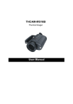
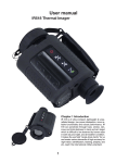
User Manual IR528 Thermal Imager User Manual User Manual Contents Contents ............................................................................................................................ 2 Introduction ....................................................................................................................... 3 Precautions ....................................................................................................................... 3 Maintenance ..................................................................................................................... 4 Repair Philosophy ............................................................................................................. 4 System Overview .............................................................................................................. 5 System Configuration ........................................................................................................ 5 System Specification ......................................................................................................... 6 Parts Described................................................................................................................. 7 Accessories ....................................................................................................................... 8 Battery Charging ............................................................................................................. 11 Quick Start Guide ............................................................................................................ 12 Focusing and Adjusting the Dioptre................................................................................. 13 Observing the Image on Video Display ........................................................................... 13 Operating the System ..................................................................................................... 14 Troubleshooting .............................................................................................................. 20 User Manual Introduction This publication provides the necessary information required to safely operate the IR528 Thermal Imager. It is important to fully check all equipment with which you have been supplied The equipment should be used, maintained and serviced by suitably trained personnel, capable of carefully following the procedures and guidelines given in this User Manual All User Manuals and leaflets should be read thoroughly before proceeding with operation of the equipment It is also advisable that all User Manuals and Instruction Leaflets supplied are kept readily available, for reference when the equipment is in general use Precautions The following precautions must be adhered to at all times and must be considered in addition to any advised precautions issued at the relevant worksite or work area • Do not direct the IR528 Thermal Imager at very high intensity radiation sources such as the sun, carbon dioxide lasers or arc welders etc • Never aim the IR528 Thermal Imager at high temperature objects when powering it on. Always replace the lens cap when the unit is not in operation • Do not use other power supply than the power supply provided together with IR528 Thermal Imager • Neither use nor store the IR528 Thermal Imager in any temperature exceeding the operating or storage range. • The interval between each powering on and powering off of the IR528 Thermal Imager shall be at least 20 seconds. • Do not connect or disconnect any cable when the IR528 Thermal Imager or any equipment connected to it is not powered off. • • Do never force any cable into or out of the interface on the IR528 Thermal Imager Power off the IR528 Thermal Imager after using it or leaving it unused for a long time after powering it on, in order to reach its maximum effective utility. • When the IR528 Thermal Imager is not in use or is to be transported, ensure that the unit and its accessories are stored in the protective carry case • The IR528 Thermal Imager incorporates precision optical equipment and static-sensitive electronics which should be protected from shock and vibration at all times • Do not attempt to open the IR528 Thermal Imager body, as this action will void the warranty User Manual The IR528 Thermal Imager utilises a Lithium Ion (Li-Ion) rechargeable battery pack. The following safety precautions must be adhered to at all times to ensure the safe use of this equipment • • • • • Do not disassemble or attempt to open the battery under any circumstances Do not expose the battery to fire or high temperatures Do not short circuit the battery Do keep the battery off moisture or water Charging of the battery should only be carried out using the recommended or supplied charging device Maintenance To ensure that the IR528 Thermal Imager is kept in good working condition and remains fully operational, the following guidelines should be adhered to at all times Non-optical surfaces The non-optical surfaces of the imager can be cleaned when required, with a soft cloth dampened with water and a mild detergent Optical surfaces The optical surfaces of the imager lens should only be cleaned when visibly dirty. Care should be taken to avoid touching the exposed lens surface, as skin acid left behind from fingerprints can be damaging to coatings and lens substrates. Use only a proprietary lens cleaning tissue Repair Philosophy Contact the manufacturer to arrange for the instrument to be returned to the manufacturer in the unlikely event of a component or system failure for repair. Caution The IR528 Thermal Imager does not incorporate any user serviceable parts. Never attempt to disassemble or modify the imager. Opening the unit invalidates the warranty User Manual System Overview Weighing less than 300g and sized a palm only, IR528 Thermal Imager is the smallest and lightest thermal imaging system available in the market. It features instant-on imaging, sharp detail differentiation, simple intuitive control, convenient observation through high-resolution OELD viewfinder (and optional accurate spot temperature measurement), thus can be used as either a hand-free viewer or a portable monocular. Ruggedized, robust and operating in thick smoke, dense fog and total darkness, no doubt it is the ideal system for firefighting, field vision and 24-hour security. And it costs you the minimal amount for ownership. System Configuration Please ensure that the following items have been correctly supplied: • • • • • IR528 Thermal Imager with 6.87mm lens OLED viewfinder Carry case & strap 2 Li-ion batteries Battery charger(INPUT:AC100-240V 50-60Hz; OUTPUT:4.2VDC • • • Video cable Helmet mount User Manual Options: • • • • 45mm IR lens RS232 cable Video cable with open interface to video displace device Convertor to Q9 connector 1.0A) User Manual System Specification Imaging Performance Detector 160×120 Uncooled Microbolometer,25um Spectral Range Focus Field of View 8 to 14µm 6.87mm (45mm optional) 32.46°×24.63°(5.09°×3.82°optional) Spatial Resolution Electronic Zoom Function Focusing 3.6 mrad (0.56mrad optional) x2 Fixed focus Image Presentation Viewfinder Video Output Display Colour Interfaces Built-in black & white OLED viewfinder PAL Composite Video 9 palettes Video/Power/ RS232 (RS232 protocol reserved) Power Source Power Supply Battery Operation Power Requirement: 4.2VDC, rechargeable Li-ion battery, field-replaceable Over 2.5 hours continuous operation <3W Environmental Operating Temperature Storage Temperature -20 to 50°C -40 to 60°C Physical Characteristics Casing color Imager Weight Black 275g (inc. 6.87mm lens, excluding battery, mount & 45mm lens) User Manual Parts Described Helmet mount 6.87mm lens Power button Battery clip Battery 45mm lens Power/Video/RS232 interface Viewfinder Operation buttons User Manual Operation buttons on the imager body: Button Function M Menu button + + button, to alter menu options’ values. - button, to alter menu options’ values. - When there is no menu displayed on the live image, press and release it shortly to alter value of Enhancement coefficient C Calibration button, to perform a NUC with the built-in shutter M C Pressing Menu and Calibration buttons simultaneously can perform a NUC without the built-in shutter Accessories Video cable Plug to a video display device Lemo connector to the imager User Manual Helmet mount 4 2 1 3 Components of the helmet mount: 1. Rotary knob 2. Button 3. Dovetail base 4. Pushbutton Mounting procedures: • • Rotate the rotary knob 1 anti-clockwise. Keep button 2 depressed, meanwhile slide the dovetail base 3 of the helmet mount to the dovetail groove of the imager till it locks in place. • Release button 2, then rotate the rotary knob 1 clockwise to fix the helmet mount onto the imager. • Mount the imager with helmet mount to a helmet, then tighten them with 4 screws through the 4 screw holes on the helmet mount. When the imager is not used for a while, press the pushbutton 4 and then move the imager upwards. Then the imager won’t block your viewing with eyes. To use the imager again, press the pushbutton 4 and then move the imager downwards. User Manual Dismounting procedures: • • Rotate the rotary knob 1 anti-clockwise. Keep button 2 depressed, slide the dovetail base 3 of the helmet mount out of the dovetail groove of the imager. • Release button 2. Battery charger LEMO connector Charge lamp Li-ion battery Charge terminal Charge terminal User Manual Battery Charging • The battery is charged in the imager via the battery charger. • Before charging, ensure the imager is powered off and the battery is inserted into the imager. • To charge the battery, insert the Lemo connector of the battery charger to the power/video/RS232 interface on the imager body. Ensure the red point of the Lemo connector is exactly aimed at the red point of the power/video/RS232 interface. • Connect the charger to a wall outlet or a socket (110~240VAC). Now charging starts. • The charge lamp is red during the charging process. When it changes to green, full charge is completed. • The approximate charging time for the battery is 4~5 hours. • The charging time may differ depending on the condition of the battery or the temperature of the environment Additional Information Warning: The imager shall never be powered on during the charging process. • All rechargeable batteries gradually lose their charge over time when they are left in storage. If the battery is to be left in storage or for a period of non-use, a 'top-off' charge should be carried out prior to use • Always remove the battery from the equipment or charger when not in use. Store the battery in a cool, dry place • Periodically wipe the metal battery terminals with a soft, dry cloth • Do not attempt to open or disassemble the battery • Do not short circuit the battery by directly connecting the metal terminals • Ensure that no metal objects touch the terminals Inserting the battery to the imager • Keep the battery clip on the imager body depressed. • Put the battery into the open battery slot with its charge terminals aimed at the metal spring chips in the slot. • Press the battery to attach it to the slot tightly. • Release the battery clip to lock the battery into place. User Manual Quick Start Guide • Ensure that the battery is fully charged and the imager is mounted steadily onto a helmet. • Mount a battery tightly to the imager. Power on the imager • The boot screen image shows up. Rotate the viewfinder dioptre to view the image clearly • Non Uniformity Correction (NUC) is performed automatically after 20 seconds and 40 seconds from switch on. • Then the imager is ready to capture image. Uncover the lens cap. Aim the imager at the target. • Press Button “M” to view menu options, press Button “+” or “-” to alter value of a respective option. • Press Button “M” to exit the menu • Perform NUC manually when necessary. • After inspection, close the lens cap. Then keep button power depressed till the process bar under live image reaches the right end. Now the imager is powered off. • Remove the battery, disconnect cables (if any) and then put the imager and accessories into the supplied safety case. Note: • To insert cables to the imager, the red point of the cables’ Lemo connector shall be exactly aimed at the red point of the power/video/RS232 interface. • To disconnect cables from the imager, keep the Lemo connector pinched while pulling it out of the interface. • Never force any cable into or out of the imager. User Manual Non Uniformity Calibration (NUC) NUC allows the imager detector to clean up the live image of noise, ensuring normalisation and sharpness of the live image If necessary, manual NUC can be performed in two methods: • Pressing button C will perform a NUC with the built-in shutter. • Pressing button M and C simultaneously will perform a NUC without the built-in shutter. Before doing this, aim the imager lens at a low temperature uniform surface, e.g. the lens cap or cloudless sky. Focusing and Adjusting the Dioptre • Focus of the 6.87mm standard lens and the 45mm tele lens is fixed. To inspect objects over a short distance, you can use the standard lens only; to inspect objects over a long distance, you need to add the 45mm lens to the standard lens. • Rotating the 45mm lens clockwise can add it to the standard lens; rotating it anti-clockwise can remove it from the standard lens. • Rotate the viewfinder to get a dioptre most convenient for observing the target with your eyes Observing the Image on Video Display Before connecting the imager and a video display device, ensure that the IR528 Thermal Imager is powered off y Connect the imager with a video display device through the video cable y Control the imager with buttons on its body. Adjusting the image quality by pressing buttons on the imager body or adjusting the display effect of the video device. y After observation, power off the imager and the video display device, disconnect the cables. User Manual Operating the System Battery status indication After the imager starts capturing image, a battery icon will be displayed at the right bottom of the live image. If the icon flickers, it indicates the battery charge is not enough and the battery needs to be replaced. If go on using the battery, the imager will automatically switch off when the charge is too low to support the imager working. Menu operation Pressing button M can bring up the system menu under the live image. • When the menu is displayed, pressing button M can toggle between each menu options. • To highlight an option, release button Menu immediately • When a menu option is highlighted, pressing button + or – can change its value. Menu 1: Auto: Auto mode. Press button + or – to switch between two modes: Auto and Semi Auto. Mode Displayed menu item Control mode Auto Brightness B,Contrast C Auto offset & Auto gain SemiAuto Brightness B,Contrast C Auto offset & Manual gain • Brightness: the expected value of actual average brightness of the entire live image or User Manual a part of the live image. • Contrast: the expected value of actual contrast of the entire live image or a part of the live image. • Offset and Gain: two parameters respectively corresponding to brightness and contrast for the system to calculate the brightness and contrast of the live image Auto mode: In this mode, users can change B and C values to set up the expected average brightness and the expected contrast of the live image. After setting these two values, the system will automatically adjust offset and gain in real time to obtain the highest image quality. Values of “B” and “C” are presented in percentage. Semi Auto mode: User Manual In this mode, users can change B value to set up the expected average brightness of the image. Then the system will automatically adjust offset in real time as per this set brightness value. Meanwhile, users can change C value to adjust the gain value. Values of “B” and “C” are presented in percentage. B: abbreviation of “Brightness”, i.e. brightness shows the value of brightness of the live image. Press “+” or “-“to increase or decrease the value of this parameter. C: abbreviation of “Contrast”, i.e. contrast shows the value of contrast of the live image. Press “+” or “-“to increase or decrease the value of this parameter. Z: zoom function. There are options of 1×, 2×. Press “+” or “-“to shift between the options User Manual Palette* : 9 palettes are available for the system. Press “+” or “-“to change polarity. User Manual Menu 2: When Palette* is highlighted, pressing button M again will turn to the second menu of the system. The menu consists of 4 options, which are exactly 4 algorithms to adjust image quality. Smooth: To switch between the normal image mode and the image smoothing mode. In smoothing mode, the live image looks more uniform. Press “+” or “-“to set its value to be 0, 1 or 2. 0 means the image is under normal mode; 1 and 2 are coefficients determining the smoothing effect. Enhance: To switch between the normal image mode and the digital detail enhancement mode. In enhancement mode, the image details are sharper to identify. Press “+” or “-“to set its value to be 0, 1 or 2. 0 means the image is under normal mode; 1 and 2 are coefficients determining the enhancement effect. Scene: To switch between the ordinary inspection scene and the special inspection scenes for which Sky & ground enhancement algorithm is used. Press “+” or “-“to set its value to be 0, 1 or 2. 0 means the image is under normal mode; 1 and 2 are coefficients determining the effect of sky & ground enhancement. Steady: To switch between the normal image mode and the stabilized image mode. Stabilization reduces the non-uniformity level of the live image. Press “+” or “-“to set its value to be 0 or 1. 0 means the image is under normal mode; 1 means the algorithm is activated. Caution: Smoothing, enhancement and scene cannot coexist with each other. Only one of them is applicable at a certain time, i.e. only one of them can be set as 1 or 2 at a time. Illustration of Sky & ground enhancement mode: To ensure a high sensitivity while simultaneously detecting high altitude, low altitude and ground that have great temperature difference from each other, most IR imagers fall into User Manual the trouble of saturation, i.e. in the image the high temperature part is too bright or the low temperature is too dark. In this case, targets in high temperature area of low altitude or in low temperature area of high altitude cannot be detected. Sky & ground enhancement mode perfectly solves the above problem, making every target in any temperature area visible & detectable. Saturated Normal Mode Sky & ground enhancement Mode Parameter saving When the imager is powered off, it automatically saves the current values of all the menu options. These saved values will be the initial values of menu options after the imager is powered on next time. User Manual Troubleshooting Problems Causes and Solutions Imager does not turn on: Battery improperly installed. Remove battery and install correctly. Battery charge is low. Recharge battery or replace with fully charged item. Battery contacts are dirty. Clean battery contacts. Imager turns off during operation: Battery charge is low. Recharge battery or replace with fully charged item. Poor battery performance: Battery may be defective. Replace battery. Low contrast or no image in Contrast is inappropriate. Adjust contrast manually. viewfinder: The lens cap is on. Remove lens cap. Dioptre of the viewfinder is inappropriate. Rotate the viewfinder to adjust dioptre. Condensation on eyepiece of viewfinder. Clean viewfinder eyepiece. Condensation on imager lens. Place imager in a dry area at room evaporates. temperature until condensation