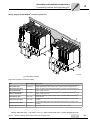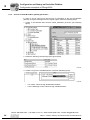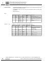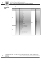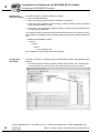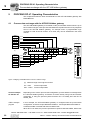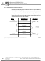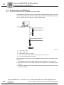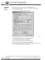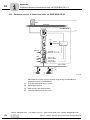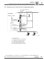
1
Drive Technology \ Drive Automation \ System Integration \ Services
Fieldbus Gateway UFF41B
DeviceNet and PROFIBUS DP
Edition 02/2009
16756428 / EN
Manual
SEW-EURODRIVE – Driving the world
Phone: 800.894.0412 - Fax: 888.723.4773 - Web: www.clrwtr.com - Email: [email protected]
1 General Information ............................................................................................... 6
1.1 Using the manual ........................................................................................... 6
1.2 Structure of the safety notes .......................................................................... 6
1.3 Rights to claim under limited warranty ........................................................... 7
1.4 Exclusion of liability ........................................................................................ 7
1.5 Copyright notice ............................................................................................. 7
2 Safety Notes ........................................................................................................... 8
2.1 Other applicable documentation .................................................................... 8
2.2 General safety notes for bus systems............................................................ 8
2.3 Safety functions ............................................................................................. 8
2.4 Hoist applications ........................................................................................... 8
2.5 Product names and trademarks ..................................................................... 8
2.6 Waste disposal............................................................................................... 9
3 Introduction .......................................................................................................... 10
3.1 Content of the manual.................................................................................. 10
3.2 Characteristics ............................................................................................. 10
3.2.1 Process data exchange .................................................................... 10
3.2.2 Parameter access ............................................................................. 10
3.2.3 Monitoring functions .......................................................................... 11
4 Assembly and Installation Instructions ............................................................. 12
4.1 Installation options of the UFF41B fieldbus gateway ................................... 12
4.2 Voltage supply ............................................................................................. 13
4.2.1 Voltage supply in the MOVIAXIS® master module ........................... 13
4.2.2 Voltage supply in the UOH21B gateway housing ............................. 15
4.3 Connecting inverters and engineering PC ................................................... 16
4.3.1 Functional description of the terminals, DIP switches
and LED of the UFF41B option ......................................................... 16
4.3.2 Connecting CAN 1 system bus (connector X33) /
CAN 2 (terminal X32) ........................................................................ 17
4.3.3 Connecting SBUSplus system bus (terminal X36) ............................. 21
4.3.4 Ethernet interface terminal (terminal X37) ........................................ 21
4.3.5 Pin assignment X37 (Ethernet for engineering) ................................ 22
4.4 Status LED of the UFF41B fieldbus gateway............................................... 23
4.5 DIP switch S1 default IP address................................................................. 24
4.5.1 TCP / IP addressing and subnetworks .............................................. 24
4.6 SD memory card type OMG4.B ................................................................... 26
4.7 Connecting the UFF41B fieldbus gateway to a DeviceNet network............. 27
4.7.1 Pin assignment X30D (DeviceNet) ................................................... 27
4.7.2 Bus termination ................................................................................. 28
4.7.3 Setting the DIP switches ................................................................... 28
4.7.4 Status LED in DeviceNet operation .................................................. 30
4.8 Connecting the UFF41B fieldbus gateway to a PROFIBUS network........... 32
4.8.1 Pin assignment X30P (PROFIBUS) .................................................. 32
4.8.2 Status LED in PROFIBUS operation ................................................. 34
4.9 Shielding and routing bus cables ................................................................. 35
5 Configuring the UFx41B Fieldbus Gateway and the Inverter........................... 36
5.1 Description of the gateway functions ........................................................... 36
5.1.1 Introduction ....................................................................................... 36
5.1.2 Autosetup .......................................................................................... 36
5.1.3 Customized configuration ................................................................. 38
5.1.4 Configuring fieldbus gateway and slave units ................................... 39
5.1.5 Data backup ...................................................................................... 41
Manual – Fieldbus Gateway UFF41B DeviceNet and PROFIBUS DP
3
5.2
Startup procedure ........................................................................................ 44
5.2.1 Checking hardware installation and communication settings ........... 44
5.2.2 Establishing an engineering connection ........................................... 44
5.2.3 Configuring the fieldbus gateways .................................................... 46
5.2.4 Last settings in the slave units .......................................................... 47
5.2.5 Monitoring and controlling process data ........................................... 49
5.2.6 Saving inverter data in the fieldbus gateway and
using MOVITOOLS® MotionStudio ................................................... 52
5.2.7 Error processing and status messages ............................................. 54
6 Configuration and Startup on DeviceNet Fieldbus ........................................... 57
6.1 Validity of EDS files for the UFF41B option ................................................. 57
6.2 Configuring PLC and master (DeviceNet scanner) ...................................... 58
6.3 Project planning examples in RSLogix5000................................................. 61
6.3.1 UFF41B fieldbus gateway with 16 process data ............................... 61
6.3.2 Access to UFF41B fieldbus gateway parameters ............................. 64
6.3.3 Access to unit parameters of lower-level units .................................. 67
7 DeviceNet Operating Characteristics ................................................................. 70
7.1 Process data exchange ............................................................................... 70
7.2 The Common Industrial Protocol (CIP) ........................................................ 73
7.2.1 CIP object directory .......................................................................... 73
7.3 Return codes of the parameterization via explicit messages ....................... 82
7.4 Terms and definitions................................................................................... 86
8 Configuration and Startup on the PROFIBUS DP-V1 Fieldbus ........................ 87
8.1 Configuring a PROFIBUS DP master .......................................................... 87
9 PROFIBUS DP-V1 Operating Characteristics .................................................... 92
9.1 Process data exchange with the UFF41B fieldbus gateway ........................ 92
9.2 PROFIBUS DP timeout ................................................................................ 93
10 Functions of PROFIBUS DP-V1........................................................................... 94
10.1 Introduction to PROFIBUS DP-V1 ............................................................... 94
10.1.1 Class 1 master (C1 master) ............................................................. 95
10.1.2 Class 2 master (C2 master) ............................................................. 95
10.1.3 Data sets (DS) ................................................................................. 95
10.1.4 DP-V1 services ................................................................................ 96
10.1.5 DP-V1 alarm handling ...................................................................... 96
10.2 Features of SEW fieldbus interfaces............................................................ 97
10.3 Structure of the DP-V1 parameter channel .................................................. 98
10.3.1 Parameterization procedure via data set 47 .................................. 100
10.3.2 DP-V1 master processing sequence .............................................. 101
10.3.3 Addressing connected inverters ..................................................... 102
10.3.4 MOVILINK® parameter requests .................................................... 103
10.3.5 PROFIdrive parameter orders ........................................................ 107
10.4 Configuring a C1 master ............................................................................ 112
10.4.1 Operating mode (DP-V1 mode) ..................................................... 112
10.4.2 Example program for SIMATIC S7 ................................................. 113
10.4.3 Technical data of DP-V1 for UFF41B fieldbus gateway ................. 114
10.4.4 Error codes of the DP-V1 services ................................................. 115
Phone: 800.894.0412 - Fax: 888.723.4773 - Web: www.clrwtr.com - Email: [email protected]
4
Manual – Fieldbus Gateway UFF41B DeviceNet and PROFIBUS DP
11 Operating MOVITOOLS® MotionStudio............................................................ 116
11.1 About MOVITOOLS® MotionStudio ........................................................... 116
11.1.1 Tasks ............................................................................................. 116
11.1.2 Establishing communication with units ........................................... 116
11.1.3 Executing functions with the units .................................................. 116
11.2 First steps .................................................................................................. 117
11.2.1 Starting the software and creating a project ................................... 117
11.2.2 Establishing communication and scanning the network ................. 117
11.3 Communication mode ................................................................................ 118
11.3.1 Overview ........................................................................................ 118
11.3.2 Selecting communication mode (online or offline) ......................... 119
11.4 Communication via USB (direct) ................................................................ 120
11.4.1 Connect the unit with the PC using USB connection cables .......... 120
11.4.2 Installing the driver ......................................................................... 121
11.4.3 Configuring USB communication ................................................... 121
11.4.4 USB communication parameters ................................................... 123
11.5 Communication via Ethernet ...................................................................... 124
11.5.1 Connecting the unit with the PC via Ethernet ................................. 124
11.5.2 Configuring the communication channel via Ethernet .................... 125
11.5.3 Setting communication parameters for SMLP ................................ 126
11.6 Communication via PROFIBUS DP/DP-V1................................................ 128
11.6.1 Communication via C2 master ....................................................... 128
11.6.2 Additionally required hardware and software ................................. 129
11.6.3 Parameterize C2 master with SIMATIC NET ................................. 130
11.6.4 Configuring communication via PROFIBUS ................................... 133
11.6.5 Communication parameters for PROFIBUS DP/DP-V1 ................. 135
11.7 Executing functions with the units .............................................................. 136
11.7.1 Parameterizing units in the parameter tree .................................... 136
11.7.2 Reading/changing unit parameters ................................................ 136
11.7.3 Starting up the units (online) .......................................................... 137
11.8 Special configuration and diagnostics tools ............................................... 138
12 Troubleshooting ................................................................................................. 139
12.1 Error messages of the fieldbus gateway .................................................... 139
12.1.1 General errors of the fieldbus gateway .......................................... 140
12.1.2 Error during process data processing ............................................ 141
12.1.3 Error during unit replacement ......................................................... 142
12.2 Diagnostic procedure for operation on DeviceNet ..................................... 143
12.3 Diagnostic procedure for operation on PROFIBUS DP-V1 ........................ 145
13 Technical Data .................................................................................................... 146
13.1 General technical data ............................................................................... 146
13.2 UFF41B fieldbus gateway .......................................................................... 147
13.3 Bus connection .......................................................................................... 148
13.4 Dimension drawings................................................................................... 149
13.4.1 Dimension drawing for fieldbus gateway UFF41B / UOH21B ........ 149
13.4.2 Dimension drawing MOVIAXIS® master module MXM / UFF41B . 150
14 Appendix ............................................................................................................. 151
14.1 Parameter access to lower-level units via DeviceNet ................................ 151
14.2 Parameter access to lower-level units via PROFIBUS DP-V1................... 152
14.3 Parameter access to lower-level units via engineering interfaces ............. 153
15 Index .................................................................................................................... 154
Phone: 800.894.0412 - Fax: 888.723.4773 - Web: www.clrwtr.com - Email: [email protected]
Manual – Fieldbus Gateway UFF41B DeviceNet and PROFIBUS DP
5
General Information
Using the manual
1
1
General Information
1.1
Using the manual
Manual
The manual is part of the product and contains important information on operation and
service. The manual is written for all employees who assemble, install, startup, and
service the product.
The manual must be accessible and legible. Make sure that persons responsible for the
system and its operation, as well as persons who work independently on the unit, have
read through the manual carefully and understood it. If you are unclear about any of the
information in this documentation, or if you require further information, contact SEWEURODRIVE.
1.2
Structure of the safety notes
The safety notes in this manual are structured as follows:
Pictogram
SIGNAL WORD
Type and source of danger.
Possible consequence(s) if the safety notes are disregarded.
•
Pictogram
Example:
Measure(s) to prevent the danger.
Signal word
Meaning
Consequences if
disregarded
DANGER
Imminent danger
Severe or fatal injuries
WARNING
Possible dangerous situation
Severe or fatal injuries
CAUTION
Possible dangerous situation
Minor injuries
NOTICE
Possible damage to property
Damage to the drive system or its
environment
TIP
Useful information or tip.
Simplifies the handling of the
drive system.
General danger
Specific danger,
e.g. electric shock
Phone: 800.894.0412 - Fax: 888.723.4773 - Web: www.clrwtr.com - Email: [email protected]
6
Manual – Fieldbus Gateway UFF41B DeviceNet and PROFIBUS DP
General Information
Rights to claim under limited warranty
1.3
1
Rights to claim under limited warranty
A requirement of fault-free operation and fulfillment of any rights to claim under limited
warranty is that you adhere to the information in the manual. Therefore, read the manual
before you start operating the device!
1.4
Exclusion of liability
You must comply with the information in the manual and the documentation of the units
connected to the fieldbus gateway to ensure safe operation and to achieve the specified
product characteristics and performance features. SEW-EURODRIVE assumes no
liability for injury to persons or damage to equipment or property resulting from nonobservance of the operating instructions. In such cases, any liability for defects is
excluded.
1.5
Copyright notice
© 2008 - SEW-EURODRIVE. All rights reserved.
Copyright law prohibits the unauthorized duplication, modification, distribution, and use
of this document, in whole or in part.
Phone: 800.894.0412 - Fax: 888.723.4773 - Web: www.clrwtr.com - Email: [email protected]
Manual – Fieldbus Gateway UFF41B DeviceNet and PROFIBUS DP
7
Safety Notes
Other applicable documentation
2
2
Safety Notes
2.1
Other applicable documentation
•
Installation and startup only by trained personnel observing the relevant accident
prevention regulations and the following documents:
– "MOVIDRIVE® MDX60B/61B" operating instructions
– "MOVITRAC® B" operating instructions
– "MOVIAXIS®" operating instructions
2.2
•
Read through these documents carefully before you commence installation and
startup of the UFF41B fieldbus gateway.
•
As a prerequisite to fault-free operation and fulfillment of warranty claims, you must
adhere to the information in the documentation.
General safety notes for bus systems
This communication system lets you adjust inverters and servo inverters to a variety of
different applications. As with all bus systems, there is a danger of invisible, external (as
far as the inverter is concerned) modifications to the parameters which give rise to
changes in the unit behavior. This may result in unexpected (not uncontrolled) system
behavior.
2.3
Safety functions
The inverters and servo drives are not allowed to perform any safety functions unless
they are subordinate to other safety systems. Use higher-level safety systems to ensure
protection of equipment and personnel.
For safety applications, ensure that the information in the following publications is
observed: "Safe Disconnection for MOVIDRIVE® B / MOVITRAC® B / MOVIAXIS®".
2.4
Hoist applications
MOVIDRIVE® MDX60B/61B, MOVITRAC® B and MOVIAXIS® must not be used as a
safety device in hoist applications.
Use monitoring systems or mechanical protection devices as safety equipment to avoid
possible damage to property or injury to people.
2.5
Product names and trademarks
The brands and product names contained within this manual are trademarks or registered trademarks of the titleholders.
Phone: 800.894.0412 - Fax: 888.723.4773 - Web: www.clrwtr.com - Email: [email protected]
8
Manual – Fieldbus Gateway UFF41B DeviceNet and PROFIBUS DP
Safety Notes
Waste disposal
2.6
2
Waste disposal
Observe the applicable national regulations.
Dispose of the following materials separately in accordance with the country-specific
regulations in force, as:
•
Electronics scrap
•
Plastic
•
Sheet metal
•
Copper
Phone: 800.894.0412 - Fax: 888.723.4773 - Web: www.clrwtr.com - Email: [email protected]
Manual – Fieldbus Gateway UFF41B DeviceNet and PROFIBUS DP
9
Introduction
Content of the manual
3
3
Introduction
3.1
Content of the manual
This user manual describes how to:
3.2
•
Connect the UFF41B fieldbus gateway to MOVIDRIVE® B, MOVITRAC® B inverters
and to the MOVIAXIS® servo inverter.
•
Startup MOVIDRIVE® B, MOVITRAC® B and MOVIAXIS® for gateway operation.
•
Startup the UFF41B fieldbus gateway with the DeviceNet and PROFIBUS DP-V1
fieldbus systems.
•
Configure the DeviceNet master with EDS files.
•
Configure the PROFIBUS DP-V1 master using GSD files.
Characteristics
The powerful, universal fieldbus interfaces of the UFF41B option enable you to use the
option to connect to higher-level automation systems via DeviceNet and PROFIBUS
DP-V1.
3.2.1
Process data exchange
The UFF41B fieldbus gateway allows for digital access to most parameters and functions via the DeviceNet and PROFIBUS interfaces. Control is performed via fast, cyclic
process data. Via this process data channel, you can enter setpoints and trigger various
control functions, such as enable, normal stop, rapid stop, etc. At the same time you can
also use this channel to read back actual values, such as actual speed, current, unit
status, error number or reference signals. In DeviceNet operation, process data are
exchanged with polled I/O and bit-strobe I/O. In PROFIBUS operation, they are exchanged via I/O data in the master.
3.2.2
Parameter access
In DeviceNet operation, the parameters of the inverter are set solely via explicit
messages.
In PROFIBUS operation, the PROFIBUS DP-V1 parameter mechanisms lets you
access any device information.
Phone: 800.894.0412 - Fax: 888.723.4773 - Web: www.clrwtr.com - Email: [email protected]
10
Manual – Fieldbus Gateway UFF41B DeviceNet and PROFIBUS DP
Introduction
Characteristics
3.2.3
3
Monitoring functions
Using a fieldbus system requires additional monitoring functions, for example, time
monitoring of the fieldbus (fieldbus timeout) or rapid stop concepts. You can determine,
for instance, which fault responses should be triggered in the event of a bus error. The
parameters for the fault response can be set in the servo inverter / inverter. A rapid stop
is useful for many applications. This is why the fieldbus gateway will stop the lower-level
drives in the event of a fieldbus timeout. As the range of functions for the control terminals is also guaranteed in fieldbus mode, you can continue to implement rapid stop
concepts using the servo inverters/inverters connected to the fieldbus gateway.
Phone: 800.894.0412 - Fax: 888.723.4773 - Web: www.clrwtr.com - Email: [email protected]
Manual – Fieldbus Gateway UFF41B DeviceNet and PROFIBUS DP
11
Assembly and Installation Instructions
Installation options of the UFF41B fieldbus gateway
4
4
Assembly and Installation Instructions
This chapter contains information on the assembly and installation of the UFF41B fieldbus gateway in a MOVIAXIS® master module MXM or in an UOH21B gateway housing.
4.1
Installation options of the UFF41B fieldbus gateway
Observe the following installation instructions:
TIP
Only SEW-EURODRIVE is allowed to install/remove the UFF41B fieldbus gateway
into/from a MOVIAXIS® master module MXM and an UOH21B gateway housing.
MOVIAXIS
®
MXM
UFF41B/ UOH21B
UFF41B
UFF41B
L18
L18
L17
L17
S2
S2
X30P
X30P
L15
X30D
L15
X30D
1
L16
1
L16
L14
L14
5
5
L13
L13
20
21
22 ON
23
24
25
26
27
20
21
22 ON
23
24
25
26
27
L11
1
2
3
L12
1
2
3
L11
X38
X38
L5 T1
X35
3
4
X36
S1
S1
L3
L3
X36
X37
1
2
3
X32
1
2
3
1
2
3
X33
XM
L2
1
2
3
X33
L1
1
2
3
1
2
3
L1
1
2
3
X32
L2
1
2
3
MOVIAXIS
X37
XM
2
1
L4
L4
2
1
Version
L5 T1
X35
3
4
Version
L12
H1
H2
X24
EURODRIVE
X26
1234567
64421AXX
Phone: 800.894.0412 - Fax: 888.723.4773 - Web: www.clrwtr.com - Email: [email protected]
12
Manual – Fieldbus Gateway UFF41B DeviceNet and PROFIBUS DP
Assembly and Installation Instructions
Voltage supply
4.2
4
Voltage supply
Voltage supply, system bus and fieldbus interfaces as well as the engineering interface
are located at different potential levels (see chapter 13.1).
4.2.1
Voltage supply in the MOVIAXIS® master module
TIP
The MOVIAXIS® master module MXM provides additional connections that are
described in the following section.
Functional description of the terminals, X5a/X5b (MOVIAXIS® master module)
MOVIAXIS® master
module MXM
1
2
3
4
X5b
1
2
3
4
X5a
59233AXX
Designation
Terminal
Function
X5b connector
X5b:1
X5b:2
X5b:3
X5b:4
DC 24 VE
DGND
DC 24 VB
BGND
Voltage supply for control electronics
Reference potential for control
electronics
Voltage supply for brake
Reference potential for brake
connection
Terminal X5a
X5a:1
X5a:2
X5a:3
X5a:4
DC 24 VE
DGND
DC 24 VB
BGND
Voltage supply for control electronics
Reference potential for control
electronics
Voltage supply for brake
Reference potential for brake
connection
•
The terminals X5a and X5b are connected in parallel. In this way, the voltage supply
of the MOVIAXIS® master module can be provided from the right to X5b or from
below to X5a. With connection to X5a, further modules can be connected via X5b
(e.g. supply module, axis module). The voltage supply for the brake (X5a/b:3, 4) is
fed through the MOVIAXIS® master module.
•
The UFF41B fieldbus gateway can be supplied from the MOVIAXIS® switched-mode
power supply (MXS) or from an external voltage source. To do so, connect X5
between the individual units.
•
If the UFF41B fieldbus gateway is connected with DC 24 V from the MOVIAXIS®
switched-mode power supply, the functioning of the option is maintained after disconnection from the power supply. This is the case if the DC link voltage is maintained or an external DC 24 V supply is present from the MOVIAXIS® switched-mode
power supply.
Phone: 800.894.0412 - Fax: 888.723.4773 - Web: www.clrwtr.com - Email: [email protected]
Manual – Fieldbus Gateway UFF41B DeviceNet and PROFIBUS DP
13
Assembly and Installation Instructions
Voltage supply
4
Wiring diagram
DC 24 V external
®
MOVIAXIS
master module MXM
®
+ MOVIAXIS
X16 switched-mode
power supply MXS
UFF41B
L18
L17
S2
X30P
1
X30D
L16
L15
L14
5
L13
20
21
22 ON
23
24
25
26
27
L12
L11
1
2
3
X38
X5b
2
1
L4
3
4
Version
L5 T1
X35
1
2
3
4
X5b
1
2
3
4
DC 24VE
DGND
DC 24VB
BGND
S1
L3
X36
1
2
3
4
X5a
1
2
3
1
2
3
X32
L2
1
2
3
1
2
3
X33
X5a
L1
XM
X37
1
2
3
4
DC 24 V for
brake supply -
+ -
DC 24 V supply
+ for control electronics
64424AEN
Phone: 800.894.0412 - Fax: 888.723.4773 - Web: www.clrwtr.com - Email: [email protected]
14
Manual – Fieldbus Gateway UFF41B DeviceNet and PROFIBUS DP
Assembly and Installation Instructions
Voltage supply
4.2.2
4
Voltage supply in the UOH21B gateway housing
Description of the terminals and LED functions
Front view
MOVITRAC® B /
compact controller
LED
Terminal
Function
LED
H1
H2
Reserved
Reserved
Connector X24:
RJ10 socket
X24:4
X24:3
X24:2
X24:1
No function.
Engineering cannot be
performed using X24.
Designation
H1
H2
X24
58905AXX
Side view
compact controller
X26
1 2 3 4 56 7
58906AXX
Designation
Terminal
Connector X26:
CAN 1 and voltage supply
(plug-in terminal)
X26:1
X24:2
X24:3
X24:4
X26:5
X26:6
X26:7
Function
CAN1H
CAN1L
DGND
Reserved
Reserved
DGND
DC 24 V
System bus CAN 1 high
System bus CAN 1 low
Reference potential control/CAN1
Reference potential for UFF41B
Voltage supply for controller
Connection of CAN 1 system bus / voltage supply (terminal X26)
The connections for CAN 1 (X26:1/2/3 and connector X33) are connected in parallel.
The UFF41B fieldbus gateway is supplied with voltage in the UOH21B gateway housing
via X26:6/7.
Phone: 800.894.0412 - Fax: 888.723.4773 - Web: www.clrwtr.com - Email: [email protected]
Manual – Fieldbus Gateway UFF41B DeviceNet and PROFIBUS DP
15
Assembly and Installation Instructions
Connecting inverters and engineering PC
4
4.3
Connecting inverters and engineering PC
4.3.1
Functional description of the terminals, DIP switches and LEDs of the UFF41B option
Connectors, LEDs and DIP switches in the upper part of the UFF41B fieldbus gateway
allow for connection to the fieldbus systems DeviceNet (see section "Connecting the
UFF41B fieldbus gateway to a DeviceNet network") and PROFIBUS-DP (see section
"Connecting the UFF41B fieldbus gateway to a PROFIBUS network").
Front view
UFF41B fieldbus
gateway
UFF41B
UFR41B
Designation
Version
L5 T1
L4
2
1
LED 1
LED 2
LED 3
LED 4
LED 5
CAN 1 status
CAN 2 status
Program status
Gateway status
Gateway error
Status of CAN 1 system bus
Status of CAN 2 system bus
Status of gateway program
Status of gateway firmware
Status of gateway error (see section "Error
messages of the fieldbus gateway")
Terminal X35:
USB connection
X35:1
X35:2
X35:3
X35:4
USB+5 V
USBUSB+
DGND
DC 5 V voltage supply
Signal USBSignal USB+
Reference potential
Terminal X36:
Connection of an
EtherCAT based
system bus (RJ45 socket)
X36
Terminal X37:
Ethernet connection
(RJ45 socket)
X37
Terminal X32:
System bus CAN 2
(electrically isolated)
(plug-in terminals)
X32:1
X32:2
X32:3
BZG_CAN 2
CAN 2H
CAN 2L
Reference potential for system bus CAN 2
System bus CAN 2 high
System bus CAN 2 low
Terminal X33:
System bus CAN 1
(plug-in terminals)
X33:1
X33:2
X33:3
DGND
CAN 1H
CAN 1L
Reference potential for system bus CAN 1
System bus CAN 1 high
System bus CAN 1 low
DIP switch
S1
Top
Bottom
Default IP address (192.168.10.4)
IP parameter from SD memory card
Memory card
M1
Memory for firmware, gateway application, gateway configuration, and inverter parameters
Button
T1
For Bootloader update
(see section "SD memory card OMG4.B")
S1
L3
X36
1
2
3
X32
L2
1
2
3
1
2
3
1
2
3
X33
L1
XM
X37
64418AXX
Function
LED
X35
3
4
LED
DIP switch
Terminal
System bus SBUSplus (in preparation)
Standard Ethernet
assignment
Ethernet for engineering
Phone: 800.894.0412 - Fax: 888.723.4773 - Web: www.clrwtr.com - Email: [email protected]
16
Manual – Fieldbus Gateway UFF41B DeviceNet and PROFIBUS DP
Assembly and Installation Instructions
Connecting inverters and engineering PC
4.3.2
4
Connecting CAN 1 system bus (terminal X33) / CAN 2 (terminal X32)
Do not connect more than 64 units to the CAN 1 or CAN 2 system bus. The system bus
supports the address range 0 to 63.
TIPS
•
The CAN 1 system bus is not electrically isolated. Therefore, it is recommended to
use the CAN 1 (X33 or X26 with UFF41B/UOH21B) interface to connect inverters
via the system bus in the control cabinet. Set the P881 SBus address parameter in
increasing order to values 1 - 16 if the slave unit is connected to CAN 1 or the fieldbus gateway.
•
The CAN 2 system bus is electrically isolated. Therefore, preferably use interface
CAN 2 (X32) for connecting field units or units in other control cabinets. Set the
P881 SBus address parameter in increasing order to values 17 - 34 if the unit is
connected to CAN 2 or the fieldbus gateway.
The CAN system bus supports transmission systems compliant with ISO 11898. For
detailed information on the CAN system bus, refer to the "MOVIDRIVE® Communication
and Fieldbus Device Profile" manual. You can order this manual from SEWEURODRIVE.
Wiring diagram for MOVIDRIVE® B, MOVITRAC® B on CAN 1 system bus
S12
ON
ON
OFF
FSC11B
X45
X46
1234567
HL
UFR41B
OFF
X31
X44
UFF41B
S2
X12
DGND 1
SC11 2
SC12 3
X32
S1
MDX60B/61B
1
2
3
1
2
3
X33
®
MOVITRAC B
1
2
3
1
2
3
64714AXX
Cable specification
•
Use a 2 x 2-core twisted and shielded copper cable (data transmission cable with
braided copper shield). Clamping without conductor end sleeves is possible in accordance with IEC 60999. The cable must meet the following specifications:
– Cable cross-section 0.2 to 1.0 mm2 (AWG 24 - AWG 18)
– Cable resistance 120 Ω at 1 MHz
– Capacitance per unit length ≤ 40 pF/m at 1 kHz
Suitable cables include CAN bus or DeviceNet cables.
Cable length
•
The permitted total cable length depends on the baud rate setting of the system bus:
–
–
–
–
125 kBaud
250 kBaud
500 kBaud
1000 kBaud
→
→
→
→
500 m
250 m
100 m
40 m
Phone: 800.894.0412 - Fax: 888.723.4773 - Web: www.clrwtr.com - Email: [email protected]
Manual – Fieldbus Gateway UFF41B DeviceNet and PROFIBUS DP
17
Assembly and Installation Instructions
Connecting inverters and engineering PC
4
Terminating
resistor
•
Switch on the system bus terminating resistor at the start and end of the CAN system
bus connection (MOVIDRIVE® B, DIP switch S12 = ON; MOVITRAC® B, DIP switch
S1 = ON). For all other devices, switch off the terminating resistor (MOVIDRIVE® B,
DIP switch S12 = OFF; MOVITRAC® B, DIP switch S1 = OFF). If the fieldbus gateway is, for example, located at the end of the CAN 2 system bus, you have to connect
a terminating resistor of 120 Ω between pins X32:2 and X32:3 (for CAN 1: Terminating resistor between pins X33:2 and X33:3).
CAUTION
•
There must not be any potential displacement between the units connected via the
CAN 2 system bus.
•
There must not be any potential displacement between the units connected via the
CAN 1 system bus.
•
Take suitable measures to avoid potential displacement, such as connecting the
unit ground connectors using a separate cable.
Phone: 800.894.0412 - Fax: 888.723.4773 - Web: www.clrwtr.com - Email: [email protected]
18
Manual – Fieldbus Gateway UFF41B DeviceNet and PROFIBUS DP
Assembly and Installation Instructions
Connecting inverters and engineering PC
4
Wiring diagram for MOVIAXIS® on CAN 1 system bus
0
1
0
1
0
[1]
1
0
1
0
1
0
1
64784AXX
[1] Terminating resistor
Overview of system connection cables
Type
Part number
Description
CAN system cable
0819 692 3
System cable UFF41B gateway CAN 1 post connector (or CAN 2) to MOVIAXIS®
supply/regenerative power module CAN 1 system bus RJ45, length: 750 mm
CAN1 connection cable,
750 mm, RJ45-RJ45
0819 7261
CAN1 connection cable between MOVIAXIS® axis system and MOVIAXIS® axis
system, length: 750 mm
CAN1 connection cable,
3000 mm, RJ45-RJ45
0819 8993
CAN1 connection cable between MOVIAXIS® axis system and MOVIAXIS® axis
system, length: 3000 mm
CAN2 adapter cable
1810 1607
CAN2 post connector between master module and CAN2 SUB-D9 MOVIAXIS®,
length: 500 mm
CAN2 connection cable
1810 1585
CAN2 SUB-D9 MOVIAXIS® and CAN2 SUB-D9 MOVIAXIS®, to connect 3 axis
modules
CAN2 connection cable
1810 1593
CAN2 SUB-D9 MOVIAXIS® and CAN2 SUB-D9 MOVIAXIS®, to connect 4 axis
modules
Terminating resistor CAN 2
1810 1615
Terminating resistor for CAN 2 connections between axis modules
Phone: 800.894.0412 - Fax: 888.723.4773 - Web: www.clrwtr.com - Email: [email protected]
Manual – Fieldbus Gateway UFF41B DeviceNet and PROFIBUS DP
19
Assembly and Installation Instructions
Connecting inverters and engineering PC
4
Wiring diagram for MOVIAXIS®, MOVIDRIVE® B and MOVITRAC® B on CAN 1 system bus
MOVIDRIVE®
X12
3 2 1
MOVIAXIS®
MOVITRAC®
0
1
0
1
0
1
S
1 ON
OF S
F
2
1
2
3
4
5
MOVITRAC®
X4
6
6
7
64783AXX
Overview of system connection cables
Type
Part number
Description
CAN1 connection cable,
750 mm, RJ45 litz wire
0819 7288
CAN connection cable MOVIAXIS® axis system to MOVIDRIVE® and MOVITRAC®,
length: 750 mm
CAN1 connection cable,
3000 mm, RJ45 litz wire
0819 7563
CAN connection cable MOVIAXIS® axis system to MOVIDRIVE® and MOVITRAC®,
length: 3000 mm
Phone: 800.894.0412 - Fax: 888.723.4773 - Web: www.clrwtr.com - Email: [email protected]
20
Manual – Fieldbus Gateway UFF41B DeviceNet and PROFIBUS DP
Assembly and Installation Instructions
Connecting inverters and engineering PC
4.3.3
4
Connecting SBUSplus system bus (terminal X36)
Terminal X36 is intended for connecting a system bus based on EtherCAT (SBUSplus).
4.3.4
Ethernet interface terminal (terminal X37)
You can connect an engineering PC to the Ethernet interface (terminal X37).
UFF41B
L5
L4
2
1
Version
X35
3
4
S1
L3
X36
1
2
3
X32
L2
1
2
3
1
2
3
1
2
3
X33
L1
XM
X37
64420AXX
The Ethernet interface (X37) supports auto crossing auto negotiation for baud rate and
duplex mode. The IP parameters are defined depending on DIP switch S1 (see section
"DIP switches S1 default IP address").
In addition to the engineering access via terminal X37, there is another engineering
access via PROFIBUS (see section "Operation of MOVITOOLS® MotionStudio").
Phone: 800.894.0412 - Fax: 888.723.4773 - Web: www.clrwtr.com - Email: [email protected]
Manual – Fieldbus Gateway UFF41B DeviceNet and PROFIBUS DP
21
Assembly and Installation Instructions
Connecting inverters and engineering PC
4
4.3.5
Pin assignment X37 (Ethernet for engineering)
Use prefabricated, shielded RJ45 plug connectors compliant with IEC 11801 edition 2.0,
category 5.
[6]
[3] [2] [1]
12
3
A
6
B
Figure 1: Pin assignment of an RJ45 plug connector
54174AXX
A = Front view
B = View from back
[1] Pin 1 TX+ Transmit Plus
[2] Pin 2 TX- Transmit Minus
[3] Pin 3 RX+ Receive Plus
[6] Pin 6 RX- Receive Minus
Connecting UFF41B fieldbus gateway to Ethernet
To connect UFF41B to the Ethernet, connect the Ethernet interface X37 (RJ45 plug
connector) to the other network stations using a category 5, class D twisted-pair cable
in accordance with IEC 11801 edition 2.0. The interface supports auto crossing and high
auto negotiation for baud rate and duplex mode.
TIP
According to IEC 802.3, the maximum cable length for 10/100 MBaud Ethernet
(10BaseT / 100BaseT), e.g. between two network stations, is 100 m.
Phone: 800.894.0412 - Fax: 888.723.4773 - Web: www.clrwtr.com - Email: [email protected]
22
Manual – Fieldbus Gateway UFF41B DeviceNet and PROFIBUS DP
Assembly and Installation Instructions
Status LED of the UFF41B fieldbus gateway
4.4
4
Status LED of the UFF41B fieldbus gateway
LED L1 (CAN 1
status)
LED L2 (CAN 2
status)
LED L3 (program
status)
The LED L1 indicates the status of the CAN 1 system bus.
Status of the L1
LED
Diagnostics
Remedy
Orange
The CAN 1 system bus is initialized.
Green
The CAN 1 system bus is initialized.
Flashing green
(0.5 Hz)
The CAN 1 system bus is currently in
SCOM suspend mode.
Flashing green
(1 Hz)
The CAN 1 system bus is currently in
SCOM On mode.
Red
The CAN 1 system bus is off (BUSOFF).
1. Check and correct the cabling of the
CAN 1 system bus.
2. Check and correct the baud rate set
for the CAN 1 system bus.
3. Check and correct the terminating
resistors of the CAN 1 system bus.
Flashing red
(1 Hz)
Warning on the CAN 1 system bus.
1. Check and correct the cabling of the
CAN 1 system bus.
2. Check and correct the baud rate set
for the CAN 1 system bus.
-
The LED L2 indicates the status of the CAN 2 system bus.
Status of the L2
LED
Diagnostics
Remedy
Orange
The CAN 2 system bus is initialized.
-
Green
The CAN 2 system bus is initialized.
-
Flashing green
(0.5 Hz)
The CAN 2 system bus is currently in
SCOM suspend mode.
-
Flashing green
(1 Hz)
The CAN 2 system bus is currently in
SCOM On mode.
-
Red
The CAN 2 system bus is off (BUSOFF).
1. Check and correct the cabling of the
CAN 2 system bus.
2. Check and correct the baud rate set
for the CAN 2 system bus.
3. Check and correct the terminating
resistors of the CAN 2 system bus.
Flashing red
(1 Hz)
Warning on the CAN 2 system bus.
1. Check and correct the cabling of the
CAN 2 system bus.
2. Check and correct the baud rate set
for the CAN 2 system bus.
LED L3 indicates the status of the gateway program.
Status of L3
Diagnostics
Remedy
Green
Gateway program is running.
-
Off
No gateway program is loaded.
Load a gateway program into the controller.
Flashing orange
(1 Hz)
Program has stopped.
Bootloader update required (see section
"SD memory card type OMG4.B")
Phone: 800.894.0412 - Fax: 888.723.4773 - Web: www.clrwtr.com - Email: [email protected]
Manual – Fieldbus Gateway UFF41B DeviceNet and PROFIBUS DP
23
Assembly and Installation Instructions
DIP switch S1 default IP address
4
LED 4 (PLC
status)
LED L5 (user)
4.5
LED L4 indicates the firmware status of the fieldbus gateway.
Status of the L4 LED
Diagnostics
Flashing green
(1 Hz)
The firmware of the fieldbus gateway
is running properly.
Red
•
•
Flashing orange
(1 Hz)
Program has stopped.
No SD card plugged in.
File system of the SC card corrupt
Remedy
Bootloader update required (see section
"SD memory card type OMG4.B")
LED L5 is lit up red if the gateway program has detected an error and if this error can
only be eliminated after diagnostics with MOVITOOLS® MotionStudio.
DIP switch S1 default IP address
With DIP switch S1, you can set a default IP address for the Ethernet connection (X37).
The set IP address is applied in the next boot process.
4.5.1
S1 switch setting
Meaning
Top
IP parameter:
• IP address: 192.168.10.4
• Subnet mask: 255.255.255.0
• Standard gateway: 1.0.0.0
Bottom
The IP parameters defined on the memory card of the UFF41B gateway are used.
The IP parameters for engineering interface X37 are entered in the file "...\System\NetConfig.cfg" in section "Ethernet 2". You can adjust the file using a text
editor (e.g. Notepad).
TCP / IP addressing and subnetworks
Introduction
The settings for the address of the IP protocol are made using the following parameters:
•
MAC address
•
IP address
•
Subnet mask
•
Standard gateway
The addressing mechanisms and subdivision of the IP networks into sub-networks are
explained in this chapter to help you set the parameters correctly.
MAC address
The MAC address (Media Access Controller) is the basis for all address settings. The
MAC address is a worldwide unique 6-byte value (48 bits) assigned to the Ethernet
device. SEW Ethernet devices have the MAC address 00-0F-69-xx-xx-xx. The MAC
address is difficult to handle for larger networks. This is why freely assignable IP
addresses are used.
IP address
The IP address is a 32 bit value that uniquely identifies a station in the network. An IP
address is represented by four decimal numbers separated by decimal points.
Example: 192.168.10.4
Phone: 800.894.0412 - Fax: 888.723.4773 - Web: www.clrwtr.com - Email: [email protected]
24
Manual – Fieldbus Gateway UFF41B DeviceNet and PROFIBUS DP
Assembly and Installation Instructions
DIP switch S1 default IP address
4
Each decimal number stands for one byte (= 8 bits) of the address and can also be
represented using binary code (see following table).
Byte 1
Byte 2
11000000
.
Byte 3
10101000
.
Byte 4
00001010
.
00000100
The IP address comprises a network address and a station address (see following
table).
Network address
Station address
192.168.10
4
The part of the IP address that denotes the network and the part that identifies the
station is determined by the network class and the subnetwork mask.
Station addresses cannot consist of only zeros or ones (binary) because they represent
the network itself or a broadcast address.
Network classes
The first byte of the IP address determines the network class and as such represents
the division into network addresses and station addresses.
Value range
Byte 1
Network class
Complete network address
(Example)
Meaning
0 - 127
A
10.1.22.3
10 = Network address
1.22.3 = Station address
128 - 191
B
172.16.52.4
172.16 = Network address
52.4 = Station address
192 - 223
C
192.168.10.4
192.168.10 = Network address
4 = Station address
This rough division is not sufficient for a number of networks. They also use an explicit,
adjustable subnetwork mask.
Subnetwork
mask
A subnetwork mask is used to divide the network classes into even finer sections. The
subnetwork mask is represented by four decimal numbers separated by decimal points,
in the same way as the IP address.
Example: 255.255.255.128
Each decimal number stands for one byte (= 8 bits) of the subnetwork mask and can
also be represented using binary code (see following table).
Byte 1
11111111
Byte 2
.
Byte 3
11111111
.
Byte 4
11111111
.
10000000
If you compare the IP addresses with the subnetwork masks, you see that in the binary
representation of the subnetwork mask all ones determine the network address and all
the zeros determine the station address (see following table).
Byte 1
IP address
Subnet mask
Byte 2
Byte 3
Byte 4
decimal
192
.
168.
.
10
.
129
binary
11000000
.
10101000
.
00001010
.
10000001
decimal
255
.
255
.
255
.
128
binary
11111111
.
11111111
.
11111111
.
10000000
The class C network with the address 192.168.10. is further subdivided into
255.255.255.128 using the subnetwork mask. Two networks are created with the
address 192.168.10.0 and 192.168.10.128.
Phone: 800.894.0412 - Fax: 888.723.4773 - Web: www.clrwtr.com - Email: [email protected]
Manual – Fieldbus Gateway UFF41B DeviceNet and PROFIBUS DP
25
Assembly and Installation Instructions
SD memory card type OMG4.B
4
The following station addresses are permitted in the two networks:
•
192.168.10.1 - 192.168.10.126
•
192.168.10.129 - 192.168.10.254
The network stations use a logical AND operation for the IP address and the subnetwork
mask to determine whether there is a communication partner in the same network or in
another network. If the communication partner is in a different network, the standard
gateway is addressed for passing on the data.
Standard gateway
The standard gateway is also addressed via a 32-bit address. The 32-bit address is represented by four decimal numbers separated by decimal points.
Example: 192.168.10.1
The standard gateway establishes a connection to other networks. In this way, a network station that wants to address another station can use a logical AND operation with
the IP address and the subnetwork mask to decide whether the desired station is located
in the same network. If this is not the case, the station addresses the standard gateway
(router), which must be part of the actual network. The standard gateway then takes on
the job of transmitting the data packages.
4.6
SD memory card type OMG4.B
The SD memory card type OMG4.B is required for operating the UFF41B fieldbus gateway and contains the firmware, the gateway program, and the gateway configuration.
With a MOVIAXIS® axis module, it is also used for data backup and automatic parameterization in case an axis needs to be replaced.
The SD memory card type OMG4.B is included in the scope of delivery of the UFF41B
fieldbus gateway.
Only use type OMG4.B memory cards in a UFF41B fieldbus gateway.
Bootloader
update
When the LEDs L3 and L4 flash orange at a 1 Hz frequency after power-on, a bootloader
update is required. Proceed as follows:
•
Do not switch off the power supply during the entire process.
•
Press the reset button T1 on the front of the UFF41B fieldbus gateway for 3 seconds.
When the bootloader update starts, only LED 4 is flashing.
•
The bootloader update has been successful when L4 flashes green.
Phone: 800.894.0412 - Fax: 888.723.4773 - Web: www.clrwtr.com - Email: [email protected]
26
Manual – Fieldbus Gateway UFF41B DeviceNet and PROFIBUS DP
Assembly and Installation Instructions
Connecting the UFF41B fieldbus gateway to a DeviceNet network
4.7
4
Connecting the UFF41B fieldbus gateway to a DeviceNet network
The following sections describes the terminals, DIP switches, and LEDs relevant for
DeviceNet fieldbus operation.
Front view
UFF41B fieldbus
gateway
UFF41B
Designation
LED
LED 18
LED 17
Terminal X30D:
DeviceNet
(plug-in terminals)
X30D:1
X30D:2
X30D:3
X30D:4
X30D:5
VCAN_L
DRAIN
CAN_H
V+
0V24
CAN_L
DRAIN
CAN_H
24 V
DIP switch S2
Switching between PROFIBUS
and DeviceNet
S2
Top
Bottom
Fieldbus interface PROFIBUS (X30P) active
Fieldbus interface DeviceNet (X30D) active
For operation via DeviceNet:
DIP switch
for setting
the MAC ID and the baud rate
20
21
22
23
24
25
The DIP switches 20 - 25 are used to set the
MAC ID (Media Access Control Identifier). The
MAC ID represents the node address (address
range 0 - 63)
26
27
Baud rate setting
Baud rate setting
X38:1
X38:2
X38:3
Reserved
Reserved
Reserved
L17
X30P
X30D
L15
L14
5
L13
L12
L11
20
21
22 ON
23
24
25
26
27
1
2
3
X38
64775AXX
Terminal X38:
CAN for safety-relevant
communication
(plug-in terminals)
4.7.1
LEDs 17 and 18 are reserved for PROFIBUS.
LED 18 is lit orange: UFF41B option is being
initialized
The two-color LEDs 13 to 16 indicate the current
status of the fieldbus interface and the DeviceNet
system.
Mod/Net
Polled I/O
Bit-strobe I/O
BUSFAULT
-
S2
1
Function
LED 16
LED 15
LED 14
LED 13
LED 12
LED 11
L18
L16
LED
DIP switch
Terminal
Reserved
Reserved
Pin assignment X30D (DeviceNet)
The assignment of connecting terminals is described in the DeviceNet specification
(Volume I, Appendix A).
DFD11B
UFF41B
1
2
3
4
5
X30D
61612BXX
The UFF41B option is opto-decoupled on the driver side in accordance with the
DeviceNet specification (Volume I, Chapter 9). This means the CAN bus driver must be
powered with 24 V voltage via the bus cable. The cable to be used is also described in
the DeviceNet specification (Volume I, Appendix B). The connection must be made
according to the color code specified in the following table.
Phone: 800.894.0412 - Fax: 888.723.4773 - Web: www.clrwtr.com - Email: [email protected]
Manual – Fieldbus Gateway UFF41B DeviceNet and PROFIBUS DP
27
Assembly and Installation Instructions
Connecting the UFF41B fieldbus gateway to a DeviceNet network
4
UFF41B and
DeviceNet
connection
4.7.2
Pin no.
Signal
Meaning
Color coding
1
V-
0V24
BK
2
CAN_L
CAN_L
BU
3
DRAIN
DRAIN
blank
4
CAN_H
CAN_H
WH
5
V+
24 V
RD
According to the DeviceNet specification, a linear bus structure without or with very short
droplines is required.
The maximum permitted cable length depends on the baud rate setting:
Baud rate
Maximum cable length
500 kBaud
100 m
250 kBaud
250 m
125 kBaud
500 m
Bus termination
In order to avoid disruptions in the bus system due to reflections, each DeviceNet segment must be terminated with 120 Ω bus terminating resistors at the first and last physical station. Connect the bus terminating resistor between connections 2 and 4 of the
bus plug.
4.7.3
Setting the DIP switches
TIP
De-energize the UFF41B fieldbus gateway before you change the DIP switch settings.
The DIP switch settings are adopted during initialization only.
UFF41B
20
21
22 ON
23
24
25
26
27
20 - 25 = MAC ID setting
26 - 27 = Baud rate setting
64419AXX
Setting the MAC
ID
The MAC ID (Media Access Control Identifier) is set on the UFF41B option using DIP
switches 20 - 25 in a binary coded manner. The MAC ID represents the node address
of the UFF41B. The UFF41B supports the address range 0 - 63.
Phone: 800.894.0412 - Fax: 888.723.4773 - Web: www.clrwtr.com - Email: [email protected]
28
Manual – Fieldbus Gateway UFF41B DeviceNet and PROFIBUS DP
Assembly and Installation Instructions
Connecting the UFF41B fieldbus gateway to a DeviceNet network
Setting the baud
rate
4
The baud rate is set using DIP switches 26 and 27.
DIP switch
Baud rate
26
27
0
0
125 kBaud
1
0
250 kBaud
0
1
500 kBaud
1
1
Invalid
A maximum of 64 DeviceNet data words can be exchanged between the DeviceNet
module and the UFF41B option. The number is set using the DeviceNet scanner.
Phone: 800.894.0412 - Fax: 888.723.4773 - Web: www.clrwtr.com - Email: [email protected]
Manual – Fieldbus Gateway UFF41B DeviceNet and PROFIBUS DP
29
Assembly and Installation Instructions
Connecting the UFF41B fieldbus gateway to a DeviceNet network
4
4.7.4
Status LED in DeviceNet operation
The UFF41B fieldbus gateway has four two-color LEDs for diagnostic of the DeviceNet
system; they indicate the current status of the UFF41B and the DeviceNet system. The
unit status corresponding to the status of the LED is described in chapter "Error
diagnostics".
LED
Designation
LED L16
(Mod/Net)
Complete LED designation
L16
MOD/NET
Module/Network status
L15
PIO
Polled I/O
L14
BIO
Bit-strobe IO
L13
BUS FAULT
BUS FAULT
The function of the L16 LED (Mod/Net = Module/Network Status) described in the
following table is specified in the DeviceNet specification.
Status of the
L16 LED
Status
Meaning
Off
Not switched on/offline
•
•
•
Unit is offline
Unit performs DUP MAC check
Unit is switched off
Flashing green
(1 s cycle)
Online and in operational
mode
•
•
The unit is online and no connection has been
established
DUP-MAC check performed successfully
A connection has not yet been established with a
master
Missing, incorrect or incomplete configuration
•
•
Lights up green
Online, operational mode
and connected
•
•
•
Online
Connection to a master has been established
Connection is active (established state)
Flashing red
(1 s cycle)
Minor fault or connection
timeout
•
•
•
A correctable fault has occurred
Polled I/O and/or bit strobe I/O connections are in the
timeout status
DUP-MAC check has detected an error
•
•
•
A correctable fault has occurred
BusOff
DUP-MAC check has detected an error
Red light
L15 LED (PIO)
Abbreviation
Critical fault or critical link
failure
The L15 (Polled I/O) LED monitors the polled I/O connection.
Status of the
L15 LED
Status
Meaning
Flashing green
(125 ms cycle)
DUP-MAC check
Unit is performing DUP-MAC check
Off
Not switched on / offline
but not DUP-MAC check
•
•
Unit is offline
Unit is switched off
Flashing green
(1 s cycle)
Online and in operational
mode
•
•
•
Unit is online
DUP-MAC check performed successfully
A polled IO connection is being established with a
master (configuring state)
Missing, incorrect or incomplete configuration
•
Lights up green
Online, operational mode
and connected
•
•
Online
A polled I/O connection has been established
(established state)
Flashing red
(1 s cycle)
Minor fault or connection
timeout
•
•
•
Invalid baud rate set via DIP switches
A correctable fault has occurred
Polled I/O connection is in timeout status
Red light
Critical fault or critical link
failure
•
•
•
A fault that cannot be remedied has occurred
BusOff
DUP-MAC check has detected an error
Phone: 800.894.0412 - Fax: 888.723.4773 - Web: www.clrwtr.com - Email: [email protected]
30
Manual – Fieldbus Gateway UFF41B DeviceNet and PROFIBUS DP
Assembly and Installation Instructions
Connecting the UFF41B fieldbus gateway to a DeviceNet network
L14 LED (BIO)
The L14 (bit-strobe I/O) LED monitors the bit-strobe I/O connection.
Status of the
L14 LED
Status
Meaning
Flashing green
(125 ms cycle)
DUP-MAC check
Unit is performing DUP-MAC check
Off
Not switched on / offline
but not DUP-MAC check
•
•
Unit is offline
Unit is switched off
Flashing green
(1 s cycle)
Online and in operational
mode
•
•
•
Unit is online
DUP-MAC check performed successfully
A BIO connection is being established with a master
(configuring state)
Missing, incorrect or incomplete configuration
•
L13 LED (BUS
FAULT)
Lights up green
Online, operational mode
and connected
•
•
Online
A BIO connection has been established (established
state)
Flashing red
(1 s cycle)
Minor fault or connection
timeout
•
•
•
Invalid number of process data is set via DIP switches
A correctable fault has occurred
Bit-strobe I/O connection is in timeout state
Red light
Critical fault or critical link
failure
•
•
•
A fault that cannot be remedied has occurred
BusOff
DUP-MAC check has detected an error
The L13 (BUS-OFF) LED indicates the physical status of the bus node.
Status of the
L13 LED
Status
Meaning
Off
NO ERROR
The number of bus errors is in the normal range (error
active status).
The unit is performing a DUP-MAC check and cannot
send any messages because no other stations are
connected to the bus (error passive state)
Flashing red
(125 ms cycle)
Flashing red
(1 s cycle)
Power-UP test
4
BUS WARNING
The number of physical bus errors is too high. No more
error telegrams are actively written to the bus (error
passive state).
Red light
BUS ERROR
•
•
BusOff state
The number of physical bus errors has increased
despite a switch to the error-passive state. Access to
the bus is switched off.
Yellow light
POWER OFF
External voltage supply has been turned off or is not
connected.
A power-up test of all LEDs is performed once the drive inverter has been switched on.
The LEDs are switched on in the following sequence:
Time [ms]
LED L16 MOD/NET
LED L15 PIO
LED L14 BIO
LED L13 BUS FAULT
0
Green
Off
Off
Off
250
Red
Off
Off
Off
500
Off
Green
Off
Off
750
Off
Red
Off
Off
1000
Off
Off
Green
Off
1250
Off
Off
Red
Off
1500
Off
Off
Off
Green
1750
Off
Off
Off
Red
2000
Off
Off
Off
Off
Phone: 800.894.0412 - Fax: 888.723.4773 - Web: www.clrwtr.com - Email: [email protected]
Manual – Fieldbus Gateway UFF41B DeviceNet and PROFIBUS DP
31
Assembly and Installation Instructions
Connecting the UFF41B fieldbus gateway to a PROFIBUS network
4
4.8
Connecting the UFF41B fieldbus gateway to a PROFIBUS network
The following sections describe the terminals, DIP switches, and LEDs relevant for
PROFIBUS operation.
Front view
UFF41B fieldbus
gateway
LED
DIP switch
Terminal
Designation
LED
LED 18
LED 17
LED 12
LED 11
Run PROFIBUS
Fault PROFIBUS
-
Status of PROFIBUS communication
Status of PROFIBUS bus electronics
Reserved
Reserved
Terminal X30P:
PROFIBUS
(Sub-D9)
X30P:9
X30P:8
X30P:7
X30P:6
X30P:5
X30P:4
X30P:3
X30P:2
X30P:1
GND (M5V)
RxD/TxD-N
N.C.
VP (P5V/100 mA)
GND (M5V)
CNTR-P
RxD/TxD-P
N.C.
N.C.
Reference potential for PROFIBUS
Signal receive transmit negative
Terminal unassigned
DC+5 V potential for bus terminator
Reference potential for PROFIBUS
PROFIBUS control signal for repeater
Signal receive transmit positive
Terminal unassigned
Terminal unassigned
DIP switch S2
Switching between
PROFIBUS and DeviceNet
S2
Top
Bottom
Fieldbus interface PROFIBUS (X30P) active
Fieldbus interface DeviceNet (X30D) active
For PROFIBUS mode: DIP
switch for setting
the PROFIBUS station
address
20
21
22
23
24
25
26
27
Significance: 1
Significance: 2
Significance: 4
Significance: 8
Significance: 16
Significance: 32
Significance: 64
In PROFIBUS operation without function
Terminal X38:
CAN for safety-relevant
communication
(plug-in terminals)
X38:1
X38:2
X38:3
Reserved
Reserved
Reserved
UFF41B
L18
L17
S2
X30P
1
X30D
L16
L15
L14
5
L13
20
21
22 ON
23
24
25
26
27
L12
L11
1
2
3
X38
64422AXX
4.8.1
Function
Pin assignment X30P (PROFIBUS)
Connection to the PROFIBUS system is made using a 9-pin sub D plug according to
IEC 61158. The T-bus connection must be made using a plug with the corresponding
configuration. The following figure shows the PROFIBUS connector that is connected to
X30P of the UFF41B fieldbus gateway.
[2]
1
6
9
5
RxD/TxD-P
RxD/TxD-N
CNTR-P
DGND (M5V)
VP (P5V/100mA)
DGND (M5V)
3
8
4
5
6
9
[3]
[1]
61766AXX
[1] 9-pin D-sub connector
[2] Signal line, twisted
[3] Conductive connection over a large area is necessary between plug housing and
the shield
Phone: 800.894.0412 - Fax: 888.723.4773 - Web: www.clrwtr.com - Email: [email protected]
32
Manual – Fieldbus Gateway UFF41B DeviceNet and PROFIBUS DP
Assembly and Installation Instructions
Connecting the UFF41B fieldbus gateway to a PROFIBUS network
UFF41B gateway
and PROFIBUS
connection
4
As a rule, the UFF41B fieldbus gateway is connected to the PROFIBUS system using a
shielded twisted-pair cable. Observe the maximum supported transmission rate when
selecting the bus connector.
The twisted-pair cable is connected to the PROFIBUS connector at pin 3 (RxD/TxD-P)
and pin 8 (RxD/TxD-N). Communication takes place using these two pins. The RS485
signals RxD/TxD-P and RxD/TxD-N must all be connected to the same contacts in all
PROFIBUS stations. Else, the bus components cannot communicate via the bus
medium.
The PROFIBUS interface sends a TTL control signal for a repeater or fiber optic adapter
(reference = pin 9) via pin 4 (CNTR-P).
Baud rates
greater than 1.5
MBaud
The UFF41B fieldbus gateway with baud rates > 1.5 MBaud can only be operated with
special 12-MBaud PROFIBUS connectors.
Bus termination
When the UFF41B fieldbus gateway is located at the start or end of a PROFIBUS
segment and when there is only one PROFIBUS cable connected to the UFF41B fieldbus gateway, you must use a plug with an integrated bus terminating resistor.
Switch on the bus terminating resistors for this PROFIBUS connector.
Setting the
station address
To set the PROFIBUS station address, use DIP switches 20 - 26 on the UFF41B fieldbus
gateway. DIP switch 27 has no function in PROFIBUS operation.
The UFF41B fieldbus gateway supports the address range 0 - 125.
UFF41B
20
21
22 ON
23
24
25
26
27
The default setting for the station address is 4:
20 → Significance: 1 × 0 = 0
21 → Significance: 2 × 0 = 0
22 → Significance: 4 × 1 = 4
23 → Significance: 8 × 0 = 0
24 → Significance: 16 × 0 = 0
25 → Significance: 32 × 0 = 0
26 → Significance: 64 × 0 = 0
64419AXX
Any change of the PROFIBUS station address during ongoing operation does not take
effect immediately. You have to switch the supply voltage of UFF41B off and then on
again for the changes to take effect.
Phone: 800.894.0412 - Fax: 888.723.4773 - Web: www.clrwtr.com - Email: [email protected]
Manual – Fieldbus Gateway UFF41B DeviceNet and PROFIBUS DP
33
Assembly and Installation Instructions
Connecting the UFF41B fieldbus gateway to a PROFIBUS network
4
4.8.2
Status LED in PROFIBUS operation
The UFF41B fieldbus gateway has two two-color LEDs for diagnostic of the PROFIBUS
system. They indicate the current status of the UFF41B and the PROFIBUS system. The
unit status corresponding to the status of the LED is described in chapter "Error
diagnostics".
LED L17 (FAULT
PROFIBUS)
LED L17 (FAULT PROFIBUS) indicates that communication via the PROFIBUS interface is working properly.
Status of the
L17 LED
Diagnostics
Remedy
Off
•
The UFF41B fieldbus gateway exchanges
data with the PROFIBUS-DP master (data
exchange status).
-
Red
•
•
Connection to the DP master has failed.
The UFF41B fieldbus gateway does not
detect the PROFIBUS baud rate.
Bus interruption has occurred.
PROFIBUS-DP master not in operation.
•
The UFF41B fieldbus gateway does not
detect the baud rate. However, the DP
master does not address the UFF41B
fieldbus gateway.
The UFF41B fieldbus gateway was not
configured in the DP master or was configured incorrectly.
•
•
•
Flashing red
(1 Hz)
•
•
LED L18 (RUN
PROFIBUS)
•
•
•
•
Check the PROFIBUS connection on
the unit.
Check project planning of the
PROFIBUS DP master.
Check all the cables in the
PROFIBUS network.
Check and correct the PROFIBUS
station address set in the UFF41B
fieldbus gateway and in the configuration software of the DP master.
Check and correct the configuration
of the DP master.
Use the GSD file SEW_600D.GSD
with the designation Adv.Gateway
UFF for configuration.
LED L18 (RUN PROFIBUS) indicates the proper functioning of the PROFIBUS electronics (hardware).
Status of the
L18 LED
Diagnostics
Remedy
Green
•
PROFIBUS hardware OK.
-
Flashing
green
(1 Hz)
•
The PROFIBUS station address set on
the DIP switches exceeds 125. If the
PROFIBUS station address is set to a
value greater than 125, the UFF41B fieldbus gateway will use PROFIBUS station
address 4.
1. Check and correct the PROFIBUS
station address on the DIP switches.
2. Switch on all drive inverters again.
The modified PROFIBUS address
will only take effect after a restart.
Orange
•
UFF41B option is being initialized.
-
Phone: 800.894.0412 - Fax: 888.723.4773 - Web: www.clrwtr.com - Email: [email protected]
34
Manual – Fieldbus Gateway UFF41B DeviceNet and PROFIBUS DP
Assembly and Installation Instructions
Shielding and routing bus cables
4.9
4
Shielding and routing bus cables
Only use shielded cables and connection elements that meet the requirements of
category 5, class D according to IEC 11801 edition 2.0.
Correct shielding of the bus cable attenuates electrical interference that can occur in
industrial environments. The following measures ensure the best possible shielding:
•
Manually tighten the mounting screws on the connectors, modules, and equipotential
bonding conductors.
•
Use only connectors with a metal housing or a metallized housing.
•
Connect the shielding in the connector over a wide surface area.
•
Apply the shielding of the bus line on both ends.
•
Route signal and bus cables in separate cable ducts. Do not route them parallel to
power cables (motor leads).
•
Use metallic, grounded cable racks in industrial environments.
•
Route the signal cable and the corresponding equipotential bonding close to each
other using the shortest possible route.
•
Avoid using plug connectors to extend bus cables.
•
Route the bus cables closely along existing grounding surfaces.
CAUTION
In case of fluctuations in the earth potential, a compensating current may flow via the
bilaterally connected shield that is also connected to the protective earth (PE). Make
sure you supply adequate equipotential bonding according in accordance with relevant
VDE regulations in such a case.
Phone: 800.894.0412 - Fax: 888.723.4773 - Web: www.clrwtr.com - Email: [email protected]
Manual – Fieldbus Gateway UFF41B DeviceNet and PROFIBUS DP
35
Configuring the UFx41B Fieldbus Gateway and the Inverter
Description of the gateway functions
5
5
Configuring the UFx41B Fieldbus Gateway and the Inverter
5.1
Description of the gateway functions
5.1.1
Introduction
With the UFF41B and UFR41B fieldbus gateways, SEW-EURODRIVE offers innovative
solutions for integrating SEW inverter technology in fieldbus systems.
For this purpose, process data of the higher-level control in the fieldbus gateway are
processed and sent via CAN (SBus) to the devices connected to the fieldbus gateway.
Type UFx41B fieldbus gateways can transmit up to 64 process data (PD) from the
fieldbus to up to 16 lower-level slave units. The data length per slave unit is limited to 16
process data.
Two different unit configurations are supported:
•
Autosetup configuration
For automatic configuration of the fieldbus gateway and connected devices.
•
Customized configuration
For individual configuration of the process data length and the CAN connection of the
individual slave units.
Special features of the UFx41B fieldbus gateways are data backup and data restoration
(see chapter "Data Backup", section "Restore mechanism") after replacement of slave
units. For this purpose, all parameters of the connected slave units are saved on the SD
card of the fieldbus gateway and a possible unit replacement is monitored. When a unit
is replaced, the fieldbus gateway automatically loads the unit parameters to the replaced
unit.
The fieldbus gateway is configured in MOVITOOLS® MotionStudio using the "UFx Gateway Configurator" tool.
5.1.2
Autosetup
The "Autosetup" function is activated in the "UFx Gateway Configurator" tool. Autosetup
results in automatic configuration of the fieldbus gateway and the slave units connected
to it, which optimally cover a wide range of applications.
The "autosetup" functions performs the following configurations automatically:
•
Stopping process data communication in direction of the SBus
•
Scanning the CAN 1 system bus to detect the connected units (MOVIAXIS®,
MOVIDRIVE® B and MOVITRAC® B; up to max. 16 units)
•
Assigning the process data width: 6 process data with MOVIAXIS® and 3 process
data with MOVIDRIVE® B and MOVITRAC® B
•
Configuring the necessary process data objects (PDO) of the MOVIAXIS® axis
modules
•
Saving the configuration in the UFx41B fieldbus gateway (no data backup)
Phone: 800.894.0412 - Fax: 888.723.4773 - Web: www.clrwtr.com - Email: [email protected]
36
Manual – Fieldbus Gateway UFF41B DeviceNet and PROFIBUS DP
Configuring the UFx41B Fieldbus Gateway and the Inverter
Description of the gateway functions
•
5
Starting process data communication
12082AEN
During unit scan, the first 16 units found in the slave unit configuration saved in the fieldbus gateway will apply.
If the value of 64 PD is exceeded due to the process data lengths set for the individual
slave units, the gateway application will automatically reduce the process data length of
the slave units. In this case, 3 PD are set for MOVIDRIVE® B and MOVITRAC® B slave
units. The remaining free PD length will be divided by the number of MOVIAXIS® slave
units. This is the resulting process data length for the individual MOVIAXIS® units. The
procedure applies no matter whether the autosetup function is enabled or not.
TIP
"Autosetup" assumes that all slave units are connected to the CAN 1 system bus.
Scanning is performed using the CAN 1 system bus only.
The start words in the process image are set in such a way that the data of the slaves
follows one another without overlapping.
The autosetup configuration is saved in the UFx41B fieldbus gateway and is checked
by scanning the slave units each time the power supply is enabled.
To ensure successful communication and configuration of MOVIAXIS® units, the
MOVIAXIS® parameter setting level must be set to "Planning Engineer".
Phone: 800.894.0412 - Fax: 888.723.4773 - Web: www.clrwtr.com - Email: [email protected]
Manual – Fieldbus Gateway UFF41B DeviceNet and PROFIBUS DP
37
Configuring the UFx41B Fieldbus Gateway and the Inverter
Description of the gateway functions
5
5.1.3
Customized configuration
The "customized configuration" function allows for configuring the process data width
individually and for using the CAN 2 terminal on the fieldbus gateway. The CAN cycle
time can be reduced by dividing the slave units among the two CAN interfaces of the
fieldbus gateway. The data transmission performance can be increased in this way.
Customized configuration means that users can configure the process data length for
each slave unit, the start word in the process image in direction of the fieldbus, and the
SBus (CAN 1 or CAN 2). Status word and data length are the same both for the process
input and process output data of the slave unit.
12103AEN
The fieldbus gateway uses these data to automatically determine the cycle time for the
CAN interfaces as well as the number, data length, and CAN-IDs of process data objects
(PDO) on the SBus. The duration of the cycle time is always the same for both CAN
interfaces.
Pressing the [Apply configuration] button saves the configuration data in the fieldbus
gateway. These are the number of slave units, their process data width, their connection
to the CAN1 or CAN2 system bus, and their timeout interval. Additionally, the settings
required for establishing the communication with the fieldbus gateway are made automatically in the MOVIAXIS® slave units. For MOVIAXIS® units with disabled "autosetup
of process data" function ("autosetup process data" selection field "off"), the user has to
set the parameters for the process data in the slave units accordingly.
Changes made to the process data configuration in the fieldbus gateway will take effect
in the fieldbus gateway by pressing the [Apply configuration] button.
Phone: 800.894.0412 - Fax: 888.723.4773 - Web: www.clrwtr.com - Email: [email protected]
38
Manual – Fieldbus Gateway UFF41B DeviceNet and PROFIBUS DP
Configuring the UFx41B Fieldbus Gateway and the Inverter
Description of the gateway functions
5.1.4
5
Configuring fieldbus gateway and slave units
If the "autosetup" or "customized configuration" functions are performed using the UFx
Gateway Configurator, then the slave unit parameters (MOVIAXIS®, MOVIDRIVE®
B and MOVITRAC® B) described in the following sections have to be made.
Setting the MOVIAXIS® servo inverter
Process data communication is automatically configured in the axis module for each
MOVIAXIS® slave unit if the fieldbus gateway was configured using the "autosetup"
function, or, in the case of "customized configuration" of this slave unit, if the "autosetup
process data" function is set to "OFF". Only the process data objects required for
communication between fieldbus gateway and MOVIAXIS® axis module are configured.
The unit-internal further processing of process data depends on the application and is
not affected by the configuration by the fieldbus gateway.
12083AEN
TIP
•
It is important that no other axis-to-axis communication between the individual
slave units was configured via the same CAN bus in order to ensure process data
exchange and engineering between fieldbus gateway and slave units.
•
If the application requires axis-to-axis communication, use the CAN2 bus of the axis
module for MOVIAXIS®, and the free CAN bus for MOVIDRIVE® B.
Phone: 800.894.0412 - Fax: 888.723.4773 - Web: www.clrwtr.com - Email: [email protected]
Manual – Fieldbus Gateway UFF41B DeviceNet and PROFIBUS DP
39
5
Configuring the UFx41B Fieldbus Gateway and the Inverter
Description of the gateway functions
Setting the MOVIDRIVE® B and MOVITRAC® B inverters
With MOVIDRIVE® B and MOVITRAC® B, the "autosetup" function does not automatically set the parameters. In this case, the following settings have to be made via the
UFx41B fieldbus gateway for operating the MOVIDRIVE® B or MOVITRAC® B inverters
(see following figure).
11845AXX
®
®
Before controlling the MOVIDRIVE B or MOVITRAC B inverter via the fieldbus gateway, you have to set control signal source (P101) and setpoint source (P100) to SBus1.
The SBus setting1 means the inverter parameters are set for control and setpoint entry
via fieldbus gateway. The inverter then responds to the process output data sent by the
master programmable controller.
It is necessary to set the SBus1 timeout interval (P883) to a value other than 0 ms for
the inverter to stop in the event of a faulty SBus communication. We recommend a value
in the range 50 to 200 ms. Activation of the control signal source and setpoint source
SBus is signaled to the higher-level controller using the "SBus mode active" bit in the
status word.
Activation of the control signal source and setpoint source SBus is signaled to the
machine controller using the "Fieldbus mode active" bit in the status word. For safety
reasons, you must also enable the MOVIDRIVE® B inverter at the terminals for control
via the fieldbus gateway. Consequently, you must wire and program the terminals in
such a way that the inverter is enabled via the input terminals. The simplest way of
enabling the inverter using terminals is, for example, to connect the DIØØ input terminal
(function /CONTROLLER INHIBIT) for MOVIDRIVE® B, and DI01 = CW/stop for
MOVITRAC® B to a +24 V signal and to program the remaining terminals to NO
FUNCTION.
Phone: 800.894.0412 - Fax: 888.723.4773 - Web: www.clrwtr.com - Email: [email protected]
40
Manual – Fieldbus Gateway UFF41B DeviceNet and PROFIBUS DP
Configuring the UFx41B Fieldbus Gateway and the Inverter
Description of the gateway functions
5
TIPS
5.1.5
•
Set the P881 SBus address parameter in increasing order to values 1 - 16 if the
slave unit is connected to the CAN 1 system bus of the fieldbus gateway. Set the
basic address of the CAN 1 system bus of the axis block to values > 0 in particular
when using MOVIAXIS® axis blocks.
•
Set the P881 SBus address parameter in increasing order to values 17 - 34 if the
slave unit is connected to the CAN 2 system bus of the fieldbus gateway.
•
The SBus address 0 is used by the UFx41B fieldbus gateway and therefore must
not be used.
•
Set P883 SBus timeout to values between 50 to 200 ms.
•
For MOVIDRIVE® B, set P889 / P899 Parameter channel 2 to ON
Data backup
12090AEN
The type UFx41B fieldbus gateway allows for saving all parameters of the connected
slave units to the SD memory card of the fieldbus gateway. Besides, the fieldbus gateway monitors a possible unit replacement and in this case loads the unit parameters
automatically to the replaced unit. The parameter sets of the slave units and the configuration data of the UFx41B fieldbus gateway are centrally saved on the SD memory card
of the fieldbus gateway and will be used when replacing a unit.
Phone: 800.894.0412 - Fax: 888.723.4773 - Web: www.clrwtr.com - Email: [email protected]
Manual – Fieldbus Gateway UFF41B DeviceNet and PROFIBUS DP
41
5
Configuring the UFx41B Fieldbus Gateway and the Inverter
Description of the gateway functions
This means the fieldbus gateway serves as data memory for the data sets of the slave
units and of the startup data of the fieldbus gateway.
Once you have taken up operation of the drive system, the data sets are copied to the
data memory (SD card) when pressing the [Data backup] button. This function lets you
save the parameter sets of each slave unit, their UUID (Universally Unique Identifier)
and the configuration data of the fieldbus gateway itself. If the parameters of individual
slave units should change after the data backup, then the change will also have to be
updated in the data backup. This can be easily done by pressing the [Save data] button
of the relevant slave unit.
When restarting the system, the system checks whether an axis has been replaced. If
yes, the data set saved at startup will automatically be loaded into the replaced axis.
This mechanism only works for units with a UUID (Universally Unique Identifier) (so far
only for MOVIAXIS®).
Automatic unit update is only performed for fieldbus gateway slave units, which means
for units the user has manually entered in the device list of the fieldbus gateway either
using the user interface or during the system bus auto scan. Units that are connected to
the SBus but are not listed in the device list of the fieldbus gateway, will neither be
included in the data backup nor in the unit replacement function.
Saving data to SD
memory card
The prerequisite for automatic update after a unit replacement is that the system has
been taken into operation and that its data sets are available on the data memory (SD
memory card for UFx) of the fieldbus gateway. These data sets are created by activating
the "Data backup" function using the UFx Gateway Configurator. Make sure that the unit
replacement function of the fieldbus gateway is active. To do so, set the "Unit replacement function" to "ON" on the "Gateway parameters" tab of the UFx Gateway Configurator.
Data backup means the data sets of the connected units are saved as well as their
UUIDs. The configuration of the fieldbus gateway is also saved.
If you want the unit replacement function to be active for all units included in the device
list, you have to enable the relevant parameters before activating data backup.
The user has to restart the SBus process data once data backup is completed. Bit 9
("configured") in the gateway status indicates that the data memory contains valid data.
Phone: 800.894.0412 - Fax: 888.723.4773 - Web: www.clrwtr.com - Email: [email protected]
42
Manual – Fieldbus Gateway UFF41B DeviceNet and PROFIBUS DP
Configuring the UFx41B Fieldbus Gateway and the Inverter
Description of the gateway functions
Restore
mechanism
5
If the unit replacement function of the fieldbus gateway is active and bit 9 ("configured")
is set, all slave units will be checked for unit replacement during startup. If a replaced
unit is detected and if the axis replacement function for this slave unit is also active, the
unit will be updated with the data set saved in the data memory.
If the unit replacement function for the fieldbus gateway is disabled, the units will not be
checked for replacements and, consequently, the slave units will not be updated.
If an error occurs during automatic update of a slave unit, no process data communication will be established with this unit. This applies for errors occurring during the update
as well as for errors while reading the UUID.
TIPS
When replacing a unit, make sure that the previous SBus address is set on the
replaced units.
This is ensured when replacing a MOVIAXIS® unit if the address on the supply module
is not changed and the fieldbus gateway is connected to the CAN 1 system bus of the
MOVIAXIS® axis block.
With MOVIDRIVE® B and MOVITRAC® B, the addresses have to be set using
parameters. This also applies to MOVIAXIS® when the gateway is connected to CAN 2
of the axis module.
Automatic unit
update after a
slave timeout
A possible cause for a slave timeout is a unit replacement while the system is running.
The UUID of the unit is read and compared with the saved UUID as soon as the slave
timeout has elapsed.
If a unit replacement is detected and the unit replacement function is activated for the
fieldbus gateway and the relevant slave, and bit 9 is set in the fieldbus gateway status,
then the replaced slave unit will be updated with the data set in the data memory.
The fieldbus gateway continues to send the timeout status word in the process image of
the relevant slave to the fieldbus master both while the UUID is being transmitted and
during a possible update of the slave unit. The process data on the SBus are not
stopped. The fieldbus gateway sends "0" signals in all process data words to the relevant slave unit.
If errors occur while checking the UUID or downloading the data set, "0" is continued to
be sent to the slave unit via SBus. The fieldbus gateway enters the error bit and an error
code in the process image of this slave.
If timeout monitoring is disabled for a slave, no slave timeout will be signaled. This is the
reason why no unit replacement verification is carried out during gateway operation. The
unit replacement function during startup of the fieldbus gateway is not affected by this
setting.
Phone: 800.894.0412 - Fax: 888.723.4773 - Web: www.clrwtr.com - Email: [email protected]
Manual – Fieldbus Gateway UFF41B DeviceNet and PROFIBUS DP
43
Configuring the UFx41B Fieldbus Gateway and the Inverter
Startup procedure
5
5.2
Startup procedure
5.2.1
Checking hardware installation and communication settings
•
Checking the CAN connection between fieldbus gateway and slave units according
to the documentation.
•
Checking the terminating resistors (120 ohms) on the UFx41B fieldbus gateway and
the last slave unit (see also chapter 4.3).
•
Setting the SBus address and baud rate (see also chapter 5.1.4).
All slave units connected to the fieldbus gateway must have different SBus
addresses but the same SBus baud rate.
You can make these settings using the keypads DBG60B, FBG11B (only for
MOVITRAC® B) or using MOVITOOLS® MotionStudio (see chapter 11.7.2).
– Set the P881 SBus address parameter in increasing order to values 1 - 16 if the
slave unit is connected to the CAN 1 system bus of the fieldbus gateway.
– SBus address 0 is used by the UFx41B gateway and must therefore not be used.
– Set P883 SBus timeout to values between 50 to 200 ms.
5.2.2
Establishing an engineering connection
Do the following for configuring units online using MOVITOOLS® MotionStudio:
1. Start MOVITOOLS® MotionStudio from the WINDOWS® start menu using the
following path:
Start\Programs\SEW\MOVITOOLS MotionStudio
2. Create a project with name and storage location.
3. Set up communication for communicating with your units.
4. Scan the network (unit scan). To do so, click the [Start network scan] button [1] in the
toolbar.
64334AXX
Phone: 800.894.0412 - Fax: 888.723.4773 - Web: www.clrwtr.com - Email: [email protected]
44
Manual – Fieldbus Gateway UFF41B DeviceNet and PROFIBUS DP
Configuring the UFx41B Fieldbus Gateway and the Inverter
Startup procedure
5
5. Make sure that all slave units connected to the fieldbus gateway are displayed after
the unit scan. If no slave units are detected, check the installation (CAN bus terminating resistors). Also check whether all slave units have different SBus addresses
with values higher than zero (see following figure).
12105AEN
6. Select the UFx41B gateway you want to configure and open the context menu with
a right mouse click. As a result you will see a number of unit-specific tools to execute
various functions with the units.
7. Open the "UFx Gateway Configurator" tool (see following figure)
12104AEN
Phone: 800.894.0412 - Fax: 888.723.4773 - Web: www.clrwtr.com - Email: [email protected]
Manual – Fieldbus Gateway UFF41B DeviceNet and PROFIBUS DP
45
Configuring the UFx41B Fieldbus Gateway and the Inverter
Startup procedure
5
5.2.3
Configuring the fieldbus gateways
Autosetup
If you want to carry out the configuration using the "autosetup" function, press the
[Autosetup] button in the UFx Gateway Configurator. All drives will be stopped.
The slave units connected to the CAN 1 system bus will be scanned and configured
automatically in the case of MOVIAXIS®. The UFx Gateway Configurator displays a
symbol during execution of the "Autosetup" function.
The autosetup function assigns the following process data widths:
•
6 process data for MOVIAXIS®, and
•
3 process data for MOVIDRIVE® B and MOVITRAC® B.
With MOVIAXIS®, all necessary process data objects (PDO) of the MOVIAXIS® axis
modules are configured automatically.
With MOVIDRIVE® B and MOVITRAC® B, the SBus address, SBus timeout, and SBus
baud rate have to be configured for the slave units as described in chapter 5.1.4.
The number of slave units and their settings are saved in the fieldbus gateway and are
checked by scanning the slave units each time power supply is enabled.
Observe that the "autosetup" function requires that all slave units are connected to the
CAN 1 system bus. Scanning is performed using the CAN 1 system bus only.
If the "Autosetup" function was executed successfully and if fieldbus communication has
already been established, then the process data are started and the UFx Gateway
Configurator indicates proper operation.
Customized
configuration
If you want to carry out the configuration using the "customized" function, press the
[Customized configuration] button in the UFx Gateway Configurator. The UFx Gateway
Configurator opens the "Process data configuration" tab. Press the [Process data - Stop]
button. All drives will be stopped.
The "customized configuration" functions lets you configure the process data width individually and is necessary if slave units are connected to the CAN 2 system bus of the
fieldbus gateway.
The CAN cycle time can be reduced by dividing the slave units among the two CAN
interfaces of the fieldbus gateway. The data transmission performance can be increased
in this way.
12103AEN
Phone: 800.894.0412 - Fax: 888.723.4773 - Web: www.clrwtr.com - Email: [email protected]
46
Manual – Fieldbus Gateway UFF41B DeviceNet and PROFIBUS DP
Configuring the UFx41B Fieldbus Gateway and the Inverter
Startup procedure
5
Set the following for each slave unit:
•
Process data length
•
SBus timeout interval
•
CAN interface (CAN 1 or CAN 2 system bus) to which the slave unit is connected
The entry in the "Start word process image" is determined automatically.
The start word in the process image in direction of the fieldbus as well as the process
data length is the same for the process input and output data of the slave unit.
Pressing the [Apply configuration] button will perform the settings automatically in the
MOVIAXIS® units where the "autosetup process data" parameter is set to "ON". If the
"autosetup process data" parameter is set to "OFF", the settings in the relevant
MOVIAXIS® unit will not be made automatically so they have to be made by the user
afterwards.
Pressing the [Process data - Start] button will start communication between fieldbus
gateway and slave unit. The following symbol appears when communication has been
established successfully.
12107AXX
5.2.4
Last settings in the slave units
Now execute the "Startup wizard" tool for every unit as you have access to all parameters of the slave units via the engineering interface of the fieldbus gateway. Doing so will
adjust the inverter to the connected motor and, if required, the control loops will be
adjusted to the load conditions of the application.
If available, you can load a matching parameter file to the inverter / servo inverter. It is
important that the SBus address and in particular the SBus baud rate are not changed.
TIP
In particular with MOVIAXIS®, you have to check the communication settings of the INPDOs and OUT-PDOs. If the communication settings were changed by loading the
parameter set, you can correct these settings by reloading the customized configuration or by executing the "autosetup" function again.
•
MOVIAXIS®
Process data communication is automatically configured in the axis module for each
MOVIAXIS® slave unit if the gateway parameter "autosetup process data" for this
unit is set to "ON". Only the process data objects required for communication
between fieldbus gateway and MOVIAXIS® axis module are configured.
Phone: 800.894.0412 - Fax: 888.723.4773 - Web: www.clrwtr.com - Email: [email protected]
Manual – Fieldbus Gateway UFF41B DeviceNet and PROFIBUS DP
47
5
Configuring the UFx41B Fieldbus Gateway and the Inverter
Startup procedure
The unit-internal further processing of process data depends on the application and
is not affected by the configuration by the fieldbus gateway.
After having configured the fieldbus gateway, you can now set the parameters for the
individual MOVIAXIS® axis modules. To do so, use the "PDO Editor" tool or
"Parameter tree" to linking the necessary IN and OUT PDOs used by the fieldbus
gateway to the relevant control and status words.
•
MOVIDRIVE® B and MOVITRAC® B
Since the fieldbus gateway does not perform an automatic configuration for these
inverters, you have to check the settings again as described in chapter 5.1.4.
Make sure that the following parameters are not changed when setting the inverter
parameters to match your application:
–
–
–
–
–
–
P100 control signal source
P101 setpoint source
P880 / P890 SBus protocol
P881 / P891 SBus address
P884 / P894 SBus baud rate
P883 / P892 SBus timout interval
Phone: 800.894.0412 - Fax: 888.723.4773 - Web: www.clrwtr.com - Email: [email protected]
48
Manual – Fieldbus Gateway UFF41B DeviceNet and PROFIBUS DP
Configuring the UFx41B Fieldbus Gateway and the Inverter
Startup procedure
5.2.5
5
Monitoring and controlling process data
Process data
diagnostics
In the UFx Gateway Configurator, open the "Process data monitor" tab (see following
figure).
12084AEN
Check the data between fieldbus gateway and master controller. To apply different
number formats to the individual numerical fields, make a right mouse click.
Phone: 800.894.0412 - Fax: 888.723.4773 - Web: www.clrwtr.com - Email: [email protected]
Manual – Fieldbus Gateway UFF41B DeviceNet and PROFIBUS DP
49
Configuring the UFx41B Fieldbus Gateway and the Inverter
Startup procedure
5
Checking
process data in
slave units
Do the following to check whether communication between fieldbus gateway and slave
unit works properly:
•
MOVIAXIS®
You can use the PDO Editor to check process data. The input process data objects
(IN-PDO) and output process data objects (OUT-PDO) are displayed (see following
figure).
12085AEN
•
®
®
MOVIDRIVE B and MOVITRAC B
In MOVITOOLS® MotionStudio, you can check the process data using the
"Parameter tree" tool in parameter group 09 "Bus diagnostics" (see following figure).
The two tools "UFx Gateway Configurator" and "Parameter tree" can be open at the
same time (see following figure).
12086AEN
Phone: 800.894.0412 - Fax: 888.723.4773 - Web: www.clrwtr.com - Email: [email protected]
50
Manual – Fieldbus Gateway UFF41B DeviceNet and PROFIBUS DP
Configuring the UFx41B Fieldbus Gateway and the Inverter
Startup procedure
Manual specification (forcing) of
process output
data
5
The process data monitor also lets you manually specify process output data without
master controller (referred to as forcing).
12084AEN
Activate force mode and enter the values in the now active fields. Clicking the "Send
process data" button will send the entered values to the slave units via SBus instead of
the valued received via fieldbus. Process input data cannot be specified manually.
Phone: 800.894.0412 - Fax: 888.723.4773 - Web: www.clrwtr.com - Email: [email protected]
Manual – Fieldbus Gateway UFF41B DeviceNet and PROFIBUS DP
51
Configuring the UFx41B Fieldbus Gateway and the Inverter
Startup procedure
5
5.2.6
Saving inverter data in the fieldbus gateway and using MOVITOOLS® MotionStudio
After having successfully configured the fieldbus gateway and after complete and
verified parameterization of the slave units, the inverter parameters of the slave units
can be saved on the SD card of the fieldbus gateway and on your PC using the project
management of MOVITOOLS® MotionStudio.
Saving data on
the SD memory
card of the fieldbus gateway
To save the data of the slave units on the SD memory card of the fieldbus gateway, click
on the [Data backup] tab in the UFx Gateway Configurator and click the [Data backup]
button. For this purpose, all drives must be at standstill and process data communication
must be stopped.
Clicking the [Data backup] button of the displayed slave units will copy the parameter
set of this unit to the SD card of the fieldbus gateway.
Setting the "Automatic update" function to "OFF" disables the restore function for this
unit after unit replacement (see also chapter 5.1.5).
Saving data using
the project
management in
MOVITOOLS®
MotionStudio
Proceed as follows to configure existing units in the network:
1. Switch to the network view with the "Network view" tab.
2. Perform a unit scan.
This will display all units that are physically connected and accessible online.
3. Select the unit you want to configure.
4. Drag the scanned unit from the network view into project view (drag and drop) or
select the [Project unit] command from the context menu.
12116AEN
This opens the "Project unit" window.
5. Use the name (signature) of the unit that is accessible online.
Phone: 800.894.0412 - Fax: 888.723.4773 - Web: www.clrwtr.com - Email: [email protected]
52
Manual – Fieldbus Gateway UFF41B DeviceNet and PROFIBUS DP
Configuring the UFx41B Fieldbus Gateway and the Inverter
Startup procedure
5
TIP
Proceed as follows if you do NOT want to transfer the name (signature) from the unit
that is available online:
•
Enter a new signature.
•
Activate the "Accept signature in online unit" control field.
Doing so ensures that the unit can be clearly identified in the future.
6. Click [Finish].
The parameters are then transferred from the unit, which can be accessed online, to
the working memory.
12117AEN
7. Confirm with [OK].
The mini symbol on the unit node will then disappear in the network view.
8. Save your project.
The parameter is then transferred from the working memory to the parameter file
where it is permanently saved.
Phone: 800.894.0412 - Fax: 888.723.4773 - Web: www.clrwtr.com - Email: [email protected]
Manual – Fieldbus Gateway UFF41B DeviceNet and PROFIBUS DP
53
Configuring the UFx41B Fieldbus Gateway and the Inverter
Startup procedure
5
5.2.7
Error processing and status messages
The fieldbus gateway distinguishes between status and error messages of the fieldbus
gateway and individual slave units. For every slave, a status word is stored in an individual parameter. The following table gives an overview of the assignment of individual
bits of the slave status word.
Status word slave
Bit
Assignment
2
Slave timeout
3
Configuration error in project planning
4
Configuration error in process data
5
Update error
9
Data backup
10
Update in progress
11
Replaced axis detected
15
Error while saving data
17
Error while reading UUID during data backup
30
Unit update after timeout
The status of the fieldbus gateway is stored in a parameter in bit code. The following
table gives an overview of the assignment of individual bits of the fieldbus gateway
status word. The fieldbus gateway status results from ORing the bits in the individual
slave states if the bit assignment in the slave and fieldbus gateway states corresponds.
Fieldbus gateway status word
Bit
Assignment
0
Malfunction
1
Fieldbus timeout
2
Slave timeout
3
Configuration error in project planning
4
Configuration error in process data
5
Update error
6
Process data started
7
Process data stopped
8
Configured
9
Data backup
10
Update in progress
11
Replaced axis detected
12
Bus scan
13
Autosetup slaves
14
SBus initialization
15
Error during data backup
30
Unit update after timeout
This allows for detailed error diagnostics. For example, if the fieldbus gateway indicates
a configuration error during configuration (bit 3), the slave where this error has occurred
can be determined from the status of the slaves. Bits indicating an error are reset during
error reset (bits 0 - 5, bit 11, bit 15, bit 30).
Phone: 800.894.0412 - Fax: 888.723.4773 - Web: www.clrwtr.com - Email: [email protected]
54
Manual – Fieldbus Gateway UFF41B DeviceNet and PROFIBUS DP
Configuring the UFx41B Fieldbus Gateway and the Inverter
Startup procedure
Communication
error between
fieldbus gateway
and slave unit
5
If the fieldbus gateway detects a timeout during communcation with a slave unit, then
the fieldbus gateway automatically shows fault number F111 in the first word of the
process image of the relevant slave unit.
A timeout is detected by monitoring the process data communication between fieldbus
gateway and slave. A communication error is automatically reset as soon as the
malfunction is eliminated.
The following parameters must be set in these units to enable the fieldbus gateway to
signal error states of connected units to the master controller:
•
MOVIDRIVE® B, MOVITRAC® B
P873 = Status word 1 or status word 3
•
MOVIAXIS® (see following figure)
12108AEN
Status word settings:
– Selection field "Layout": Progr. layout/fault code
– Selection field "Bit 5: Malfunction"
This status word is linked with the corresponding output process data object (see
following figure).
12109AEN
Phone: 800.894.0412 - Fax: 888.723.4773 - Web: www.clrwtr.com - Email: [email protected]
Manual – Fieldbus Gateway UFF41B DeviceNet and PROFIBUS DP
55
Configuring the UFx41B Fieldbus Gateway and the Inverter
Startup procedure
5
TIP
The fieldbus gateway does not verify correct parameter setting of the status word.
A deviating parameter setting will cause the controller to not correctly detect communication timeouts with the slave units or other errors.
Fieldbus timeout
The fieldbus gateway detects a failed communication with the master controller (fieldbus
master). In this case, the fieldbus gateway sends "0" signals to all slave units in their
process image and in this way stops all drives using the set rapid stop ramp. Fieldbus
communication will automatically be resumed after a fieldbus timeout.
Used CAN IDs
The following CAN IDs are used for communication between fieldbus gateway and slave
units.
Number of
Calculation of CAN IDs of
process data per drive
CAN telegrams
process inputs PI
process outputs PO
3 process data for
MOVIDRIVE® B and
MOVITRAC® B
1 CAN telegram
8 x SBus address
8 x SBus address + 1
1 to 4 process data for
MOVIAXIS®
1 CAN telegram
8 x SBus address + 3
8 x SBus address + 0
5 to 8 process data for
MOVIAXIS®
2 CAN telegrams
1. CAN telegram:
8 x SBus address + 3
1. CAN telegram:
8 x SBus address + 0
2. CAN telegram:
8 x SBus address + 4
2. CAN telegram:
8 x SBus address + 1
1. CAN telegram:
8 x SBus address + 3
1. CAN telegram:
8 x SBus address + 0
2. CAN telegram:
8 x SBus address + 4
2. CAN telegram:
8 x SBus address + 1
3. CAN telegram:
8 x SBus address + 5
3. CAN telegram:
8 x SBus address + 2
1. CAN telegram:
8 x SBus address + 3
1. CAN telegram:
8 x SBus address + 0
2. CAN telegram:
8 x SBus address + 4
2. CAN telegram:
8 x SBus address + 1
3. CAN telegram:
8 x SBus address + 5
3. CAN telegram:
8 x SBus address + 2
4. CAN telegram:
8 x SBus address + 7
4. CAN telegram:
8 x SBus address + 6
9 to 12 process data for
MOVIAXIS®
13 to 16 process data for
MOVIAXIS®
3 CAN telegrams
4 CAN telegrams
TIPS
A sychronization telegram is also transmitted to ensure data consistency:
SyncID for CAN 1 and CAN 2 = 1
This calculation directive ensures the consistency of IDs calculated for MOVIAXIS®
using the "Single-axis positioning" technology editor.
Phone: 800.894.0412 - Fax: 888.723.4773 - Web: www.clrwtr.com - Email: [email protected]
56
Manual – Fieldbus Gateway UFF41B DeviceNet and PROFIBUS DP
Configuration and Startup on DeviceNet Fieldbus
Validity of EDS files for the UFF41B option
6
I
6
0
Configuration and Startup on DeviceNet Fieldbus
This chapter provides you with information on project planning for the DeviceNet master
and startup of the UFF41B fieldbus gateway for fieldbus operation.
TIP
The current versions of the EDS files for UFF41B are available on the SEW website
under the heading "Software".
6.1
Validity of EDS files for the UFF41B option
TIP
Do not edit or amend the entries in the EDS file. SEW assumes no liability for inverter
malfunctions caused by a modified EDS file!
The current EDS file SEW_GATEWAY_UFF.eds is available for configuring the master
(DeviceNet scanner) for UFF41B:
Install the following files using the RSNetWorx software to build the DeviceNet network
via the UFF41B fieldbus gateway. Proceed as follows:
•
Select the menu item [Tools] / [EDS Wizard] in RSNetWorx. You will be prompted to
enter the names of the EDS and icon files.
•
The files will be installed. For more details on the installation of the EDS file, refer to
the Allen Bradley documentation for RSNetWorx.
•
After installation, the device is available in the device list under the entry
"Vendor/SEW EURODRIVE GmbH".
Phone: 800.894.0412 - Fax: 888.723.4773 - Web: www.clrwtr.com - Email: [email protected]
Manual – Fieldbus Gateway UFF41B DeviceNet and PROFIBUS DP
57
I
6
0
6.2
Configuration and Startup on DeviceNet Fieldbus
Configuring PLC and master (DeviceNet scanner)
Configuring PLC and master (DeviceNet scanner)
The following examples refer to the usage of an Allen-Bradley-PLC ControlLogix 1756L61 together with the RSLogix 5000 programming software and the DeviceNet RSNetWorx configuration software for DeviceNet.
After adding the DeviceNet Scanner to the I/O configuration, the file *.dnt containing the
DeviceNet configuration is selected. To view and edit the DeviceNet configuration, you
can launch RSNetWorx from this dialog (see following figure).
11744AXX
In RSNetWorx for DeviceNet (see following figure), either perform an online scan or add
the required devices to the graph by drag and drop. The address specified under the
symbol of the device (in the example: 02) must be identical with the MAC ID set on
UFF41B using DIP switches. If the required devices are not in the selection list,
corresponding EDS files have to be registered via [Tools] / [Wizard].
11958AXX
Phone: 800.894.0412 - Fax: 888.723.4773 - Web: www.clrwtr.com - Email: [email protected]
58
Manual – Fieldbus Gateway UFF41B DeviceNet and PROFIBUS DP
Configuration and Startup on DeviceNet Fieldbus
Configuring PLC and master (DeviceNet scanner)
I
6
0
In online mode, you can check and set the "Pd configuration" (process data configuration) of UFF41B when reading out the device properties (see following figure).
11959AXX
The parameter "Pd configuration" indicates the number (1 ... 64) of process data words
set (16-bit) and defines the I/O parameters for the DeviceNet scanner (see following
figure).
11960AXX
Phone: 800.894.0412 - Fax: 888.723.4773 - Web: www.clrwtr.com - Email: [email protected]
Manual – Fieldbus Gateway UFF41B DeviceNet and PROFIBUS DP
59
6
I
0
Configuration and Startup on DeviceNet Fieldbus
Configuring PLC and master (DeviceNet scanner)
After adding the IFF41B fieldbus gateway to the scan list, the number of polled I/O Bytes
must be set to 2 × number of PD (e. g. number of PD = 16, number of polled input bytes
= 32 and output bytes = 32) via "Edit I/O Parameters". When the DeviceNet
configuration is saved and downloaded into the scanner, RSNetWorx can be closed.
Depending on the DeviceNet configuration and the mapping rules in the scanner, the
data from and to DeviceNet units is packed into a DINT array that is transferred from the
scanner to the local I/O tags of the Logix processor.
In order not to have to search for the data from a certain device in this array manually,
the "DeviceNet Tag Generator" tool automatically generates copy commands and two
controller tags (input & output as byte arrays) for each DeviceNet device.
The tag name contains the MAC ID of the DeviceNet unit and POL_I for polled input data
or POL_O for polled output data (see following figure).
11961AXX
Phone: 800.894.0412 - Fax: 888.723.4773 - Web: www.clrwtr.com - Email: [email protected]
60
Manual – Fieldbus Gateway UFF41B DeviceNet and PROFIBUS DP
I
Configuration and Startup on DeviceNet Fieldbus
Configuration examples in RSLogix5000
6.3
Configuration examples in RSLogix5000
6.3.1
UFF41B fieldbus gateway with 16 process data
6
0
1. Set the DIP switches on UFF41B to
•
•
Adjust the baud rate to the DeviceNet
Set the address (MAC-ID) to a value used by no other node
2. Insert the UFF41B fieldbus gateway in the DeviceNet configuration as shown in
chapter "Configuring PLC and master (DeviceNet scanner)".
3. Set the number of process data words of the UFF41B fieldbus gateway to 16.
4. Integration into the RSLogix project can now begin.
To do so, create a controller tag with a user-defined data type to create a simple
interface to the inverter’s process data (see following figure).
11962AXX
The description for the process input and output data of the controller tag can match
the definition of the process data (PD) in the inverters.
5. In order to copy the data of the UFF41B fieldbus gateway to the new data structure,
CPS commands are added into the "MainRoutine" that reads the data from the local
I/O (see following figure).
Phone: 800.894.0412 - Fax: 888.723.4773 - Web: www.clrwtr.com - Email: [email protected]
Manual – Fieldbus Gateway UFF41B DeviceNet and PROFIBUS DP
61
6
I
0
Configuration and Startup on DeviceNet Fieldbus
Configuration examples in RSLogix5000
Make sure that this CPS command is executed after the automatically generated (by
DeviceNet Tag Generator) DNet_ScannerInputsRoutine.
11963AXX
In order to copy the data from the new data structure to the UFF41B fieldbus gateway, CPS commands are added into the "MainRoutine" that writes the data to the
local I/O.
These CPS commands are executed after the automatically generated (by
DeviceNet Tag Generator) DNet_Scanner_OutputsRoutine.
11964AXX
Phone: 800.894.0412 - Fax: 888.723.4773 - Web: www.clrwtr.com - Email: [email protected]
62
Manual – Fieldbus Gateway UFF41B DeviceNet and PROFIBUS DP
Configuration and Startup on DeviceNet Fieldbus
Configuration examples in RSLogix5000
I
6
0
6. Now save the project and transfer it to the PLC. Set the PLC to Run Mode and set
the Scanner CommandRegister.Run to "1" to activate the data exchange via
DeviceNet.
You can now read the actual values from the UFF41B fieldbus gateway and write
setpoint values.
11965AXX
The process data should correspond with the values displayed in the Gateway
Configurator in MOVITOOLS® MotionStudio (see chapter "Configuring the UFx41B
fieldbus gateway and inverters").
Phone: 800.894.0412 - Fax: 888.723.4773 - Web: www.clrwtr.com - Email: [email protected]
Manual – Fieldbus Gateway UFF41B DeviceNet and PROFIBUS DP
63
I
6
0
6.3.2
Configuration and Startup on DeviceNet Fieldbus
Configuration examples in RSLogix5000
Access to UFF41B fieldbus gateway parameters
In order to get an easy-to-use read access to parameters of the UFF41B fieldbus
gateway via explicit messages and the register object, follow the following steps:
1. Create a user-defined data structure "SEW_Parameter_Channel" (see following
figure).
11764AXX
2. Define the following controller tags (see figure below).
11765AXX
3. Create a rung for the "ReadParameter" execution (following figure).
11766AXX
•
•
For contact, select the tag "ReadParameterStart"
For the Message Control, select the tag "ReadParameter"
Phone: 800.894.0412 - Fax: 888.723.4773 - Web: www.clrwtr.com - Email: [email protected]
64
Manual – Fieldbus Gateway UFF41B DeviceNet and PROFIBUS DP
Configuration and Startup on DeviceNet Fieldbus
Configuration examples in RSLogix5000
I
6
0
4. Click on
in the MSG instruction to open the "Message Configuration" window
(see following figure).
11767AXX
Select "CIP Generic" as "message type". Fill the other fields in the following order:
A
B
C
D
E
F
G
Source Element = ReadParameterRequest.Index
SourceLength = 12
Destination = ReadParameterResponse.Index
Class = 7hex
Instance = 1
Attribute = 4hex
Service Code = ehex
The service type is set automatically.
5. The target device is to be specified on the Communication tab (see following figure).
11768AXX
The path consists of:
•
•
•
Name of the scanner (e. g. DNet_Scanner)
2 (always 2)
Slave address (e. g. 11)
Phone: 800.894.0412 - Fax: 888.723.4773 - Web: www.clrwtr.com - Email: [email protected]
Manual – Fieldbus Gateway UFF41B DeviceNet and PROFIBUS DP
65
6
I
0
Configuration and Startup on DeviceNet Fieldbus
Configuration examples in RSLogix5000
6. After downloading the changes to the PLC, the index of the parameter to be read can
be entered at ReadParameterRequest.Index. By altering ReadParameterStart to "1"
the read request is executed once (see following figure).
11966BXX
On response to the read request, ReadParameterResponse.Index should indicate
the read index and ReadParameterResponse.Data should contain the read data. In
this example, the timeout interval of the UFF41B fieldbus gateway (index 8606) set
by the scanner has been read (012Chex = 0.3 s).
You can check the value in the MOVITOOLS® MotionStudio parameter tree (see
figure below). The tooltip of a parameter displays for example index, subindex, factor,
etc. of the parameter.
11969AXX
Phone: 800.894.0412 - Fax: 888.723.4773 - Web: www.clrwtr.com - Email: [email protected]
66
Manual – Fieldbus Gateway UFF41B DeviceNet and PROFIBUS DP
Configuration and Startup on DeviceNet Fieldbus
Configuration examples in RSLogix5000
6.3.3
I
6
0
Access to unit parameters of lower-level units
Access to unit parameters of, for example MOVITRAC® B connected to the UFF41B
fieldbus gateway via SBus, is the same as access to unit parameters of the UFF41B
fieldbus gateway itself (see chapter "Accessing parameters of the UFF41B fieldbus
gateway").
The only difference is that Read/WriteParameterRequest.SubChannel1 is to be set to
3 and Read/WriteParameterRequest.SubAddress1 must be set to the SBus address
of MOVITRAC® B connected to UFF41B (see figure below).
11775BXX
In this example, MOVITRAC® B connected to a CAN 1 system bus of the UFF41B option
with SBus address 7 read the value 150 rpm from P160 Fixed setpoint n11 (index 8489).
For a list of subchannels and subaddresses, refer to the next chapter.
Phone: 800.894.0412 - Fax: 888.723.4773 - Web: www.clrwtr.com - Email: [email protected]
Manual – Fieldbus Gateway UFF41B DeviceNet and PROFIBUS DP
67
6
I
0
Configuration and Startup on DeviceNet Fieldbus
Configuration examples in RSLogix5000
Only a few additions are necessary for activating write access to a parameter of lowerlevel units:
•
Create the controller tags (see following figure)
11771AXX
•
Create a rung for executing the "WriteParameter" command (see following figure).
11772AXX
For contact, select the tag "WriteParameterStart"
For message control, select the tag "WriteParameter"
•
Click on
in the MSG instruction to open the "Message Configuration" window
(see following figure).
11773AXX
Fill the other fields in the following sequence:
–
–
–
–
–
–
–
Source Element = WriteParameterRequest.Index
Source Length = 12
Destination = WriteParameterResponse.Index
Class = 7hex
Instance = 2
Attribute = 4hex
Service Code = 10hex
The service type is set automatically.
Phone: 800.894.0412 - Fax: 888.723.4773 - Web: www.clrwtr.com - Email: [email protected]
68
Manual – Fieldbus Gateway UFF41B DeviceNet and PROFIBUS DP
Configuration and Startup on DeviceNet Fieldbus
Configuration examples in RSLogix5000
•
I
6
0
After downloading the changes to the PLC, index and value to be written into the
parameter can be entered at WriteParameterRequest.Index and WriteParameterRequest.Data. Changing the WriteParameterStart control bit to "1" executes the
write command once (see following figure).
11967BXX
On response to the write request, WriteParameterResponse.Index should give the
written index and WriteParameterResponse.Data should contain the written data.
In this example, MOVITRAC® B connected to a CAN 1 system bus of the UFF41B
option with SBus address 1 wrote the value 150 rpm toP160 Fixed setpoint n11
(index 8489).
You can check the value in the MOVITOOLS® MotionStudio parameter tree or the
PLC Editor. The tooltip of a parameter displays for example index, subindex, factor,
etc. of the parameter.
Phone: 800.894.0412 - Fax: 888.723.4773 - Web: www.clrwtr.com - Email: [email protected]
Manual – Fieldbus Gateway UFF41B DeviceNet and PROFIBUS DP
69
DeviceNet Operating Characteristics
Process data exchange
7
7
DeviceNet Operating Characteristics
7.1
Process data exchange
Polled I/O
The polled I/O messages correspond to the process data telegrams sent to the UFF41B
fieldbus gateway. Up to a maximum of 64 process data words can be exchanged
between controller and UFF41B fieldbus gateway. The process data length is set using
the DeviceNet scanner.
TIP
The set process data length influences the process data lengths of the polled I/O as
well as of the bit-strobe I/O messages.
The process data length of the bit-strobe I/O messages can include up to four process
data words. If the value for the process data length set via DIP switches is less than
four, it will be accepted. If the value is set greater than four, the process data length
will be automatically limited to four.
Timeout
response with
polled I/O
The timeout is triggered by the UFF41B option. The timeout interval must be set by the
master after the connection has been established. The DeviceNet specification refers to
an "expected packet rate" rather than a timeout interval in this case. The expected packet rate is calculated on the basis of the timeout interval using the following formula:
tTimeout_inverter = tTimeout_interval_polled_IO = 4 x tExpected_packet_rate_polled_IO
The expected packet rate can be set using the connection object class 5, instance 2,
attribute 9. The range of values runs from 0 ms to 65535 ms in 5 ms steps.
The expected packet rate for the polled I/O connection is converted into the timeout
interval and displayed in the device as timeout interval in index 8606 in the bus diagnostics in the parameter tree.
This timeout interval is retained in the device when the polled I/O connection is disconnected, and the device switches to timeout status after the timeout interval has elapsed.
The timeout interval must only be set via bus.
If a timeout occurs for the polled I/O messages, this connection type enters timeout
status. Incoming polled I/O messages are no longer accepted.
The timeout triggers the timeout response set in the inverter.
The timeout can be reset via DeviceNet using the reset service of the connection object
(class 0x05, instance 0x02, undetermined attribute), by disconnecting the connection,
by using the reset service of the identity object (class 0x01, instance 0x01, undetermined attribute), or by restarting the UFF41B fieldbus gateway.
Phone: 800.894.0412 - Fax: 888.723.4773 - Web: www.clrwtr.com - Email: [email protected]
70
Manual – Fieldbus Gateway UFF41B DeviceNet and PROFIBUS DP
DeviceNet Operating Characteristics
Process data exchange
Bit-strobe I/O
7
The SEW fieldbus device profile does not include the bit-strobe I/O messages. The
messages represent a DeviceNet-specific process data exchange. The master sends a
broadcast message that is 8 bytes (= 64 bits) long. One bit in this message is assigned
to each station in accordance with its address. The value of this bit may be 0 or 1,
triggering two different responses in the recipient.
Bit
value
Meaning
LED BIO
0
Sends back process input data only
Green light
1
Trigger fieldbus timeout reaction and send back process input data
Flashing red
NOTICE
The LED L14 (BIO) on the front of the UFF41B option can be used for distinguishing
between the timeout triggered by the bit-strobe telegram and a real timeout in the
connection. The LED L14 (BIO) lights up green when bit-strobe messages are received
cyclically.
LED L14 (BIO) flashing red means there is a timeout in the bit-strobe connection and
no more bit-strobe telegrams are accepted. Each participant that has received this bitstrobe I/O message responds with its current process input data. The length of the
process input data corresponds to the process data length for the polled I/O connection. The process input data length can be up to four process data.
The following table shows the data range of the bit-strobe request message which
represents the allocation of stations (= station address) to data bits.
Example: For example, the participant with station address (MAC ID) 16 only processes
bit 0 in data byte 2.
Byte
offset
7
6
5
4
3
2
1
0
0
ID 7
ID 6
ID 5
ID 4
ID 3
ID 2
ID 1
ID 0
1
ID 15
ID 14
ID 13
ID 12
ID 11
ID 10
ID 9
ID 8
2
ID 23
ID 22
ID 21
ID 20
ID 19
ID 18
ID 17
ID 16
3
ID 31
ID 30
ID 29
ID 28
ID 27
ID 26
ID 25
ID 24
4
ID 39
ID 38
ID 37
ID 36
ID 35
ID 34
ID 33
ID 32
5
ID 47
ID 46
ID 45
ID 44
ID 43
ID 42
ID 41
ID 40
6
ID 55
ID 54
ID 53
ID 52
ID 51
ID 50
ID 49
ID 48
7
ID 63
ID 62
ID 61
ID 60
ID 59
ID 58
ID 57
ID 56
Phone: 800.894.0412 - Fax: 888.723.4773 - Web: www.clrwtr.com - Email: [email protected]
Manual – Fieldbus Gateway UFF41B DeviceNet and PROFIBUS DP
71
DeviceNet Operating Characteristics
Process data exchange
7
Timeout
response with
bit-strobe I/O
The timeout is triggered by the UFF41B option. The timeout interval must be set by the
master after the connection has been established. The DeviceNet specification refers to
an "expected packet rate" rather than a timeout interval in this case. The expected packet rate is calculated on the basis of the timeout interval using the following formula:
tTimeout_BitStrobe_IO = 4 x tExpected_Packet_Rate_BitStrobe_IO
It can be set using connection object class 5, instance 3, attribute 9. The range of values
runs from 0 ms to 65535 ms in 5 ms steps.
If a timeout occurs for the bit-strobe I/O messages, this connection type enters timeout
status. Incoming bit-strobe I/O messages are no longer accepted. The timeout is not
passed to the UFF41B fieldbus gateway.
The timeout can be reset as follows:
•
Via DeviceNet using the reset service of the connection object (class 0x05, instance
0x03, undetermined attribute)
•
By disconnecting the connection
•
Using the reset service of the identity object (class 0x01, instance 0x01, undetermined attribute)
Phone: 800.894.0412 - Fax: 888.723.4773 - Web: www.clrwtr.com - Email: [email protected]
72
Manual – Fieldbus Gateway UFF41B DeviceNet and PROFIBUS DP
DeviceNet Operating Characteristics
The Common Industrial Protocol (CIP)
7.2
7
The Common Industrial Protocol (CIP)
DeviceNet is integrated into the Common Industrial Protocol (CIP).
In the Common Industrial Protocol, all unit data can be accessed via objects. The
objects listed in the following table are integrated in the UFF41B option.
7.2.1
Class [hex]
Name
01
Identity object
03
DeviceNet Object
05
Connection Object
07
Register Object
0F
Parameter Object
CIP object directory
Identity object
•
The identity object contains general information on the EtherNet/IP device.
•
Class code: 01hex
None of the class attributes are supported.
Class
Instance 1
Attribute
Access
Name
Data type
Default value [hex]
Description
1
Get
Vendor ID
UINT
013B
SEW-EURODRIVE GmbH & Co KG
2
Get
Device Type
UINT
0064
Manufacturer-specific type
3
Get
Product Code
UINT
000D
Product no.16: UFF41B gateway
4
Get
Revision
STRUCT of
Major Revision
USINT
Minor Revision
USINT
5
Get
Status
WORD
6
Get
Serial number
UDINT
7
Get
Product Name
SHORT_STRING
Revision of the identity object, depends on
firmware version
See "Coding of attribute 5 status"
Unique serial number
SEW GATEWAY UFF41B
Product name
Phone: 800.894.0412 - Fax: 888.723.4773 - Web: www.clrwtr.com - Email: [email protected]
Manual – Fieldbus Gateway UFF41B DeviceNet and PROFIBUS DP
73
DeviceNet Operating Characteristics
The Common Industrial Protocol (CIP)
7
•
Coding of attribute 5 "Status":
Bit
Name
Description
0
Owned
Controlling connection is active
1
-
Reserved
2
Configured
Configuration complete
3
-
Reserved
4-7
Extended Device Status
See "coding extended device status (bits 4 - 7)"
8
Minor Recoverable Fault
Minor fault that can be remedied
9
Minor Unrecoverable Fault
Minor fault that cannot be remedied
10
Major Recoverable Fault
Major fault that cannot be remedied
11
Major Unrecoverable Fault
Major fault that cannot be remedied
12 - 15
-
Reserved
•
Coding of the "extended device status " (bits 4 - 7):
Value [binary]
Supported
services
Description
0000
Unknown
0010
At least one faulty IO connection
0101
No IO connection established
0110
At least one IO connection active
Service code [hex]
Service name
Instance
05
Reset
X
0E
Get_Attribute_Single
X
Phone: 800.894.0412 - Fax: 888.723.4773 - Web: www.clrwtr.com - Email: [email protected]
74
Manual – Fieldbus Gateway UFF41B DeviceNet and PROFIBUS DP
DeviceNet Operating Characteristics
The Common Industrial Protocol (CIP)
DeviceNet object
•
The DeviceNet object provides information on the DeviceNet communication
interface.
•
Class code: 03hex
7
Class
Attribute
Access
Name
Data type
Default value [hex]
Description
1
Get
Revision
UINT
0002
Revision 2
Attribute
Access
Name
Description
1
Get
MAC ID
Depending on DIP switch (0 - 63)
Depending on DIP switch (0 - 2)
Instance 1
Supported
services
2
Get
Baud rate
3
Get
BOI
4
Get/Set
Bus-off counter
5
Get
Allocation information
6
Get
MAC-ID switch changed
Information as to whether DIP switch settings vary from
MAC ID
7
Get
Baud rate switch
changed
Information as to whether DIP switch settings vary from
baud rate
8
Get
MAC-ID switch value
DIP switch setting for MAC ID
9
Get
Baud rate switch value
Actual DIP switch settings for baud rate
Error counter of the physical CAN interface (0 - 255)
Service code [hex]
Service name
Class
Instance
0E
Get_Attribute_Single
X
X
10
Set_Attribute_Single
-
X
Phone: 800.894.0412 - Fax: 888.723.4773 - Web: www.clrwtr.com - Email: [email protected]
Manual – Fieldbus Gateway UFF41B DeviceNet and PROFIBUS DP
75
DeviceNet Operating Characteristics
The Common Industrial Protocol (CIP)
7
Connection
object
•
The process and parameter data connections are defined in the connection object.
•
Class code: 05hex
Class
None of the class attributes are supported.
Instance
Communication
1
Explicit message
2
Polled I/O
3
Bit-Strobe I/O
Instance 1 - 3
Supported
services
Attribute
Access
Name
1
Get
State
2
Get
Instance type
3
Get
Transport Class trigger
4
Get
Produce connection ID
5
Get
Consume connection ID
6
Get
Initial com characteristics
7
Get
Produced connection size
8
Get
Consumed connection size
9
Get/Set
Expected packet rate
12
Get
Watchdog time-out action
13
Get
Produced connection path len
14
Get
Produced connection path
15
Get
Consumed connection path len
16
Get
Consumed connection path
17
Get
Production inhibit time
Service code [hex]
Service name
Instance
0x05
Reset
X
0x0E
Get_Attribute_Single
X
0x10
Set_Attribute_Single
X
Phone: 800.894.0412 - Fax: 888.723.4773 - Web: www.clrwtr.com - Email: [email protected]
76
Manual – Fieldbus Gateway UFF41B DeviceNet and PROFIBUS DP
DeviceNet Operating Characteristics
The Common Industrial Protocol (CIP)
Register object
Class
•
The register object is used to access an SEW parameter index.
•
Class code: 07hex
7
None of the class attributes are supported.
The MOVILINK® parameter services are mapped in the nine instances of the register
object. The "Get_Attribute_Single" and "Set_Attribute_Single" services are used for
access.
As the register object is designed so that INPUT objects can only be read and OUTPUT
objects can be read and written, the options listed in the following table are available for
addressing the parameter channel.
Resulting MOVILINK® service with
Instance
INPUT OUTPUT
Get_Attribute_Single
Set_Attribute_Single
1
INPUT
READ parameter
Invalid
2
OUTPUT
READ
WRITE parameter
3
OUTPUT
READ
WRITE VOLATILE parameter
4
INPUT
READ MINIMUM
Invalid
5
INPUT
READ MAXIMUM
Invalid
6
INPUT
READ DEFAULT
Invalid
7
INPUT
READ SCALING
Invalid
8
INPUT
READ ATTRIBUTE
Invalid
9
INPUT
READ EEPROM
Invalid
Phone: 800.894.0412 - Fax: 888.723.4773 - Web: www.clrwtr.com - Email: [email protected]
Manual – Fieldbus Gateway UFF41B DeviceNet and PROFIBUS DP
77
7
DeviceNet Operating Characteristics
The Common Industrial Protocol (CIP)
Get_Attribute_Single
Get_Attribute_Single
Set_Attribute_Single
Get_Attribute_Single
Set_Attribute_Single
Get_Attribute_Single
Input
(Instance 1)
READ
Output
(Instance 2)
WRITE
Output
(Instance 3)
Input
(Instance 4)
WRITE VOLATILE
READ MINIMUM
DPRAM
Get_Attribute_Single
Input
(Instance 5)
Get_Attribute_Single
Input
(Instance 6)
Get_Attribute_Single
Input
(Instance 7)
READ SCALING
Get_Attribute_Single
Input
(Instance 8)
READ ATTRIBUTE
Get_Attribute_Single
Input
(Instance 9)
READ EEPROM
DeviceNet (CIP)
READ MAXIMUM
READ DEFAULT
SEW fieldbus profile
Figure 2: Description of the parameter channel
62367AEN
Phone: 800.894.0412 - Fax: 888.723.4773 - Web: www.clrwtr.com - Email: [email protected]
78
Manual – Fieldbus Gateway UFF41B DeviceNet and PROFIBUS DP
DeviceNet Operating Characteristics
The Common Industrial Protocol (CIP)
7
Instance 1 - 9
Attribute
Access
Name
Data type
Default value
[hex]
Description
1
2
Get
Bad Flag
BOOL
00
0 = good / 1 = bad
Get
Direction
BOOL
00
01
00 = Input register
01 = Output register
3
Get
Size
UINT
0060
Data length in bits (96 bits = 12 bytes)
4
Get/Set
Data
ARRAY of
BITS
Data in format of the SEW parameter
channel
TIPS
Explanation of the attributes:
•
Attribute 1 indicates whether an error occurred during the previous access to the
data field.
•
Attribute 2 indicates the direction of the instance.
•
Attribute 3 indicates the data length in bits
•
Attribute 4 represents the parameter data. When accessing attribute 4, the SEW
parameter channel must be attached to the service telegram. The SEW parameter
channel consists of the elements listed in the following table.
Name
Data type
Description
Index
UINT
SEW unit index
Data
UDINT
Data (32 bit)
Subindex
BYTE
SEW unit subindex
Reserved
BYTE
Reserved (must be "0")
Subaddress 1
BYTE
0
Subchannel 1
BYTE
0
Parameter of the
UFF41B itself
Subaddress 2
BYTE
Reserved (must be "0")
Subchannel 2
BYTE
Reserved (must be "0")
1 ...
e.g. SBus address of units connected to
the SBus of UFF41B
3
Lower-level bus system, e.g. SBus 1
The subchannels and subaddresses apply to the UFF41B fieldbus gateway depending
on the lower-level bus system.
Subchannel 1
Interface
Value range subaddress 1
0
UFF41B itself
0
1
Reserved
0
2
EtherCAT X36 (in preparation)
3
SBus1 (X33 and X26)
1 - 16
4
SBus2 (X32)
17 - 32
See the "Appendix" for a schematic representation of parameter access to lower-level
units.
Supported
services
Service code [hex]
Service name
Instance
0x0E
Get_Attribute_Single
X
0x10
Set_Attribute_Single
X
Phone: 800.894.0412 - Fax: 888.723.4773 - Web: www.clrwtr.com - Email: [email protected]
Manual – Fieldbus Gateway UFF41B DeviceNet and PROFIBUS DP
79
DeviceNet Operating Characteristics
The Common Industrial Protocol (CIP)
7
Parameter object
•
The fieldbus parameters of the UFF41B option can be addressed directly via the
instance using the parameter object.
•
In exceptional cases, you can also use the parameter object to access SEW
parameters.
•
Class code: 0Fhex
Class
Instance 1 - 133
Attribute
Access
Name
Data type
Default value
[hex]
Description
2
Get
Max Instance
UINT
0085
Maximum instance = 133
8
Get
Parameter
Class
Descriptor
UINT
0009
Bit 0: Supports parameter instances
Bit 3: Parameters are saved permanently
9
Get
Configuration Assembly Interface
UINT
0000
Configuration assembly is not
supported.
Instances 1 - 133 provide access to the fieldbus parameters.
Attribute
Access
Name
Data type
Default value
[hex]
Description
1
Set/Get
Parameter
UINT
2
Get
Link Path
Size
USINT
00
No link is specified.
3
Get
Link Path
Packed
EPATH
00
Not used
4
Get
Descriptor
WORD
0000
Read/write parameter
Parameter that is to be read or
written (see section "UFF41B fieldbus parameters")
5
Get
Data type
EPATH
00C8
UDINT
6
Get
Data Size
USINT
04
Data length in bytes
Phone: 800.894.0412 - Fax: 888.723.4773 - Web: www.clrwtr.com - Email: [email protected]
80
Manual – Fieldbus Gateway UFF41B DeviceNet and PROFIBUS DP
DeviceNet Operating Characteristics
The Common Industrial Protocol (CIP)
UFF41B fieldbus
parameters
Instance
Access
1
Get/Set
2
Get
3
Get
4
Get
5
Get
6 - 69
Get
70 - 133
Get
Group
Device
parameters
Name
Meaning
PD configuration
Process data configuration
Timeout time
Timeout interval
Fieldbus type
DeviceNet
Baud rate
Baud rate via DIP switches
Station address
MAC-ID via DIP switches
PO
monitor
PO1 setpoint to
PO64 setpoint
Monitor of the
process output data words
PI monitor
PI1 actual value to
PI64 actual value
Monitor of the
process input data words
7
TIP
The data format for these instances deviates from the SEW fieldbus profile to meet the
DeviceNet specification.
Supported
services
Service code [hex]
Service name
Class
Instance
0E
Get_Attribute_Single
X
X
10
Set_Attribute_Single
-
X
Phone: 800.894.0412 - Fax: 888.723.4773 - Web: www.clrwtr.com - Email: [email protected]
Manual – Fieldbus Gateway UFF41B DeviceNet and PROFIBUS DP
81
DeviceNet Operating Characteristics
Return codes of the parameterization via explicit messages
7
7.3
Return codes of the parameterization via explicit messages
SEW-specific
return codes
The return codes that SEW units issue in case of incorrect parameterization are independent of the fieldbus. However, the return codes are sent back in a different format
when using DeviceNet. The following table shows the data format for a parameter
response message.
Byte offset
0
1
2
3
Function
MAC ID
Service code [=94hex]
General Error Code
Additional code
Example
01hex
94hex
1Fhex
10hex
•
MAC ID is the DeviceNet address
•
The Service code of an error telegram is always 94hex
•
The general error code of a manufacturer-specific return code is always 1Fhex
•
The additional code is described in the table in the "Additional code" section.
•
General Error Codes D0hex and D1hex signal protocol-specific errors to
MOVILINK®, such as incorrect address information (see section "MOVILINK®specific return codes").
The table shows the proprietary error 10hex = Illegal parameter index as an example.
Return codes
from DeviceNet
DeviceNet-specific return codes are sent in the error message if the data format is not
maintained during transmission or if a service is performed which has not been implemented. The coding of these return codes is described in the DeviceNet specification
(see section "General Error Codes").
Timeout of
explicit
messages
The timeout is triggered by the UFF41B option. The timeout interval must be set by the
master after the connection has been established. The DeviceNet specification refers to
an "expected packet rate" rather than a timeout interval in this case. The expected packet rate is calculated on the basis of the timeout interval using the following formula:
tTimeout_ExpliciteMessages = 4 x tExpected_Packet_Rate_ExpliciteMessages
It can be set using connection object class 5, instance 1, attribute 9. The range of values
runs from 0 ms to 65535 ms in 5 ms steps.
If a timeout is triggered for the explicit messages, this connection type for the explicit
messages is automatically dropped provided that the polled I/O or bit-strobe
connections are not in the ESTABLISHED state. This is the default setting of DeviceNet.
The connection for explicit messages must be re-established to communicate with these
messages again. The timeout is not passed to the UFF41B fieldbus gateway.
Phone: 800.894.0412 - Fax: 888.723.4773 - Web: www.clrwtr.com - Email: [email protected]
82
Manual – Fieldbus Gateway UFF41B DeviceNet and PROFIBUS DP
DeviceNet Operating Characteristics
Return codes of the parameterization via explicit messages
General error
codes
7
DeviceNet-specific error codes
General error
code (hex)
Error name
Description
Resource unavailable
The source required for performing the service is unavailable
08
Service not supported
The service is not supported for the selected class/instance
09
Invalid attribute value
Invalid attribute data have been sent
Reserved for DeviceNet
00 - 01
02
Reserved for DeviceNet
03 - 07
Reserved for DeviceNet
0A
0B
Already in requested
mode/state
The selected object is already in the requested mode/state
0C
Object state conflict
The selected object cannot perform the service in its current
status
Reserved for DeviceNet
0D
0E
Attribute not settable
It is not possible to access the selected object for writing.
0F
Privilege violation
Violation of access right
10
Device state conflict
The current status of the device makes it impossible to perform
the required service
11
Reply data too large
The length of the transmitted data is longer than the size of the
receive buffer
Reserved for DeviceNet
12
13
Not enough data
The length of the transferred data is too short for the service to
be performed
14
Attribute not supported
The selected attribute is not supported
15
Too much data
The length of the transferred data is too long for the service to
be performed
16
Object does not exist
The selected object is not implemented in the device
Reserved for DeviceNet
17
18
No stored attribute data
The requested data have not been stored previously
19
Store operation failure
The data could not be stored because an error occurred while
saving them
Reserved for DeviceNet
1A - 1E
1F
Vendor specific error
Vendor specific error (see "SEW Fieldbus Device Profile" manual)
20
Invalid parameter
Invalid parameter.
This error message is used when a parameter does not satisfy
the requirements of the specification and/or the requirements of
the application.
21 - CF
Future extensions
Reserved by DeviceNet for additional definitions
D0 - DF
Reserved for Object
Class and service
errors
Use this area if an occurring error cannot be entered in one of
the error groups listed above.
Phone: 800.894.0412 - Fax: 888.723.4773 - Web: www.clrwtr.com - Email: [email protected]
Manual – Fieldbus Gateway UFF41B DeviceNet and PROFIBUS DP
83
DeviceNet Operating Characteristics
Return codes of the parameterization via explicit messages
7
MOVILINK®specific return
codes
MOVILINK®-specific error codes.
Corresponds to
General
Error Code
0xD0
0xD1
MOVILINK®
Error Code
MOVILINK®
Aditional Code
Additional
code
Description
0xF0
Unknown error
0xF1
Illegal Service
0x01
0xF2
No Response
0x02
0xF3
Different Address
0x03
0xF4
Different Type
0x04
0xF5
Different Index
0x05
0xF6
Different Service
0x06
0xF7
Different Channel
0x07
0xF8
Different Block
0x08
0xF9
No Scope Data
0x09
0xFA
Illegal Length
0x0A
0x00
0xFB
Illegal Address
0xFC
Illegal Pointer
0x0B
0xFD
Not enough memory
0x0D
0xFE
System Error
0x0E
0x05
0x0C
0xF0
Communication does not exist
0x0F
0xF1
Communication not initialized
0x10
0xF2
Mouse conflict
0x11
0xF3
Illegal Bus
0x12
0xF4
FCS Error
0x13
0xF5
PB Init
0x14
0xF6
SBUS - Illegal Fragment Count
0x15
0xF7
SBUS - Illegal Fragment Type
0x16
0xF8
Access denied
0x17
0xF9 - FE
Not used
Phone: 800.894.0412 - Fax: 888.723.4773 - Web: www.clrwtr.com - Email: [email protected]
84
Manual – Fieldbus Gateway UFF41B DeviceNet and PROFIBUS DP
DeviceNet Operating Characteristics
Return codes of the parameterization via explicit messages
Additional code
7
The additional code contains SEW-specific return codes for incorrect parameter setting
of the drive inverter.
Additional code (hex)
Meaning
00
No error
10
Illegal parameter index
11
Function/parameter not implemented
12
Read access only
13
Parameter lock is active
14
Factory setting is active
15
Value for parameter too large
16
Value for parameter too small
17
Required option card missing for this function/parameter
18
Error in system software
19
Parameter access only via RS-485 process interface to X13
1A
Parameter access only via RS485 diagnostics interface
1B
Parameter is access-protected
1C
Controller inhibit required
1D
Invalid value for parameter
1E
Factory setting was activated
1F
Parameter was not saved in EEPROM
20
Parameter cannot be changed with enabled output stage
Phone: 800.894.0412 - Fax: 888.723.4773 - Web: www.clrwtr.com - Email: [email protected]
Manual – Fieldbus Gateway UFF41B DeviceNet and PROFIBUS DP
85
DeviceNet Operating Characteristics
Terms and definitions
7
7.4
Terms and definitions
Term
Description
Allocate
Provides a service for setting up a connection.
Attributes
Attribute of an object class or instance. Describes the characteristics of the
object class or instance in more detail.
BIO - Bit-Strobe I/O
All stations can be addressed with a broadcast message. The addressed
stations respond with the process input data.
Class
DeviceNet object class
Device-Net scanner
Plug-in module for the Allen Bradley PLC which connects the PLC fieldbus to
the peripheral devices.
DUP-MAC check
Duplicate MAC ID test
Explicit message body
Includes the class no., instance no., attribute no. and the data.
Explicit message
Parameter data message; assists in addressing the DeviceNet objects.
Get_Attribute_Single
Read service for a parameter.
Instance
Instance of an object class. Divides the object classes into additional subgroups.
MAC ID
Media Access Control Identifier: node address of the device.
M-File
Provides the data range between the PLC and the scanner module.
Mod/Net
Module/network
Node ID
Node address = MAC ID
PIO - Polled I/O
Process data channel of DeviceNet; allows process output data to be sent and
process input data to be received.
Release
Provides a service for setting up a connection.
Reset
Provides a service for resetting an error.
Rung
SLC500 program line
Service
Service performed via bus, e.g. read service, write service, etc.
Set_Attribute_Single
Write service for a parameter.
Phone: 800.894.0412 - Fax: 888.723.4773 - Web: www.clrwtr.com - Email: [email protected]
86
Manual – Fieldbus Gateway UFF41B DeviceNet and PROFIBUS DP
Configuration and Startup on the PROFIBUS DP-V1 Fieldbus
Configuring a PROFIBUS DP master
8
Configuration and Startup on the PROFIBUS DP-V1 Fieldbus
8.1
Configuring a PROFIBUS DP master
I
8
0
You need a GSD file to configure a PROFIBUS DP master for the UFF41B fieldbus
gateway.
TIP
The current version of the EDS file for UFF41B is available on the SEW website
under the heading "Software".
GSD file for
PROFIBUS
DP/DP-V1
The GSD file SEW_600D.GSD corresponds to GSD revision 4. The device master data
files standardized by the PROFIBUS user organization can be read by all PROFIBUS
DP masters.
Configuration tool
DP master
File name
All DP configuration tools to IEC 61158
For DP master
standard
SEW_600D.GSD
Siemens S7 hardware configuration
for all S7 DP masters
TIP
Do not change or expand entries in the GSD file! SEW assumes no liability for UFF41B
fieldbus gateway or connected inverter malfunctions caused by a modified GSD file.
General configuration procedure
Proceed as follows for configuring the UFF41B fieldbus gateway with PROFIBUS DP
interface:
1. Install (copy) the GSD file according to the requirements of your configuration software (see manuals of your configuration software or the section "Installing the GSD
file in STEP7", below). Once the file has been installed properly, the device appears
next to the slave stations with the designation Adv.Gateway UFF.
2. To configure the UFF41B fieldbus gateway, now insert Adv. Gateway UFF in the
PROFIBUS structure and assign the PROFIBUS station address.
3. Select the process data configuration required for your application (see section "DP
Configurations").
4. Enter the I/O or peripheral addresses for the configured data widths.
After configuration, you can start PROFIBUS DP. The red Fault Profibus LED indicates
the status of the configuration (OFF = configuration OK).
Phone: 800.894.0412 - Fax: 888.723.4773 - Web: www.clrwtr.com - Email: [email protected]
Manual – Fieldbus Gateway UFF41B DeviceNet and PROFIBUS DP
87
8
I
0
Configuration and Startup on the PROFIBUS DP-V1 Fieldbus
Configuring a PROFIBUS DP master
Installing the
GSD file in STEP7
Proceed as follows to install the GSD file in STEP7:
1. Start the Simatic Manager.
2. Open an existing project and start the hardware configuration.
3. Close the project window in the HW Config. A new file version cannot be installed
when the project window is open.
4. In the menu, click on [Extras] / [Install new GSD...] and select the new GSD file with
the name SEW_600D.GSD.
The software installs the GSD file and the associated bitmap files in the STEP7 system.
The SEW drive is available under the following path in the hardware catalog: PROFIBUS
DP
+--Additional PERIPHERAL UNITS
+--Drives
+---SEW
+--DPV1
+---Adv. Gateway UFF
The installation of the new GSD file is now complete.
Configuration
with STEP7
Proceed as follows for configuring the UFF41B fieldbus gateway with PROFIBUS DP
interface:
1. Use drag and drop to add the interface module with the name "Adv. Gateway UFF"
to the PROFIBUS structure and enter the station address (see figure below).
12052AEN
Phone: 800.894.0412 - Fax: 888.723.4773 - Web: www.clrwtr.com - Email: [email protected]
88
Manual – Fieldbus Gateway UFF41B DeviceNet and PROFIBUS DP
Configuration and Startup on the PROFIBUS DP-V1 Fieldbus
Configuring a PROFIBUS DP master
I
8
0
2. The UFF41B fieldbus gateway is now preconfigured with the 3PD configuration. To
change the PD configuration, you have to delete the 3 PD module in slot 3. Next, add
another PD module (e.g. the maximum configuration 64 PD) to slot 3 from the folder
"Adv. Gateway UFF" (see figure below).
12053AEN
Slots 4 to 18 can be configured in the same way. In the following figure, the maximum
configuration 64 PD is distributed among 4 slots (mapping 64 data words in smaller
peripheral areas).
12054AEN
Phone: 800.894.0412 - Fax: 888.723.4773 - Web: www.clrwtr.com - Email: [email protected]
Manual – Fieldbus Gateway UFF41B DeviceNet and PROFIBUS DP
89
8
I
0
Configuration and Startup on the PROFIBUS DP-V1 Fieldbus
Configuring a PROFIBUS DP master
Optionally, you can perform project planning for a MOVILINK® parameter channel in
the cyclic process data. To do so, delete the "Empty" module from slot 2 and replace
it with the module "Param (4 words)" using the drag and drop function.
Enter the I/O or peripheral addresses for the configured data widths in the 'I Address'
[1] and 'Q Address' [2] columns.
DP configuration
To enable the UFF41B fieldbus gateway to support the type and number of the input and
output data used for transmission, the DP master must transmit the corresponding DP
configuration to the UFF41B fieldbus gateway. The configuration telegram comprises
the DP configurations for slots 1 to 18. The number of process data depends on the
number of slave units and their process data width.
You can:
•
Control the UFF41B fieldbus gateway via process data
•
Read or write parameters using the parameter channel
The following tables contain additional information on possible DP configurations.
•
The "Parameter data/Process data configuration" column displays the name of the
configuration. These names also appear in a selection list in the configuration software for the DP master.
•
The "DP configurations" column shows the configuration data that are sent to the
UFF41B fieldbus gateway when the link to the PROFIBUS DP system is being
established.
Slot 1:
Parameter data
configuration
Meaning / notes
DP configurations
Empty
Reserved
0x00
Parameter data
configuration
Meaning / notes
DP configurations
Empty
Reserved
0x00
Slot 2:
®
MOVILINK parameter channel
configured
0xC0, 0x87, 0x87
Process data
configuration
Meaning / notes
DP configurations
1 PD
Process data exchange via
1 process data word
0xC0, 0xC0, 0xC0
2 PD
Process data exchange via
2 process data words
0xC0, 0xC1, 0xC1
3 PD
Process data exchange via
3 process data words
0xC0, 0xC2, 0xC2
4 PD
Process data exchange via
4 process data words
0xC0, 0xC3, 0xC3
5 PD
Process data exchange via
5 process data words
0xC0, 0xC4, 0xC4
6 PD
Process data exchange via
6 process data words
0xC0, 0xC5, 0xC5
7 PD
Process data exchange via
7 process data words
0xC0, 0xC6, 0xC6
8 PD
Process data exchange via
8 process data words
0xC0, 0xC7, 0xC7
Param (4words)
Slots 4 to 18:
Phone: 800.894.0412 - Fax: 888.723.4773 - Web: www.clrwtr.com - Email: [email protected]
90
Manual – Fieldbus Gateway UFF41B DeviceNet and PROFIBUS DP
Configuration and Startup on the PROFIBUS DP-V1 Fieldbus
Configuring a PROFIBUS DP master
Configuration
example
Process data
configuration
Meaning / notes
DP configurations
9 PD
Process data exchange via
9 process data words
0xC0, 0xC8, 0xC8
10 PD
Process data exchange via
10 process data words
0xC0, 0xC9, 0xC9
11 PD
Process data exchange via
11 process data words
0xC0, 0xCA, 0xCA
12 PD
Process data exchange via
12 process data words
0xC0, 0xC7, 0xC7
13 PD
Process data exchange via
13 process data words
0xC0, 0xCC, 0xCC
14 PD
Process data exchange via
14 process data words
0xC0, 0xCD, 0xCD
15 PD
Process data exchange via
15 process data words
0xC0, 0xCE, 0xCE
16 PD
Process data exchange via
16 process data words
0xC0, 0xCF, 0xCF
32 PD
Process data exchange via
32 process data words
0xC0, 0xDF, 0xDF
64 PD
Process data exchange via
64 process data words
0xC0, 0xFF, 0xFF
I
8
0
Slot 1: Empty
Slot 2: Param (4 words)
Slot 3: 10 PD
Configuration telegram sent to the UFF41B fieldbus gateway: 0x00 0xC0 0xC87 0x87
0xC0 0xC9 0xC9
Data integrity
Consistent data is data that always has to be transmitted between the higher-level
controller and the UFF41B fieldbus gateway as one block and must never be transmitted
separately.
Data integrity is particularly important for transmitting position values or complete
positioning tasks. The reason for this is that data which is not transmitted consistently
could be from different program cycles of the higher-level controller, which would lead
to undefined values being transmitted to the UFF41B fieldbus gateway.
For PROFIBUS DP, data communication between the higher-level controller and the
UFF41B fieldbus gateway is carried out with the setting "Data integrity over entire
length".
Phone: 800.894.0412 - Fax: 888.723.4773 - Web: www.clrwtr.com - Email: [email protected]
Manual – Fieldbus Gateway UFF41B DeviceNet and PROFIBUS DP
91
I
9
0
9
PROFIBUS DP-V1 Operating Characteristics
Process data exchange with the UFF41B fieldbus gateway
PROFIBUS DP-V1 Operating Characteristics
This chapter describes the basic characteristics of the UFF41B fieldbus gateway with
PROFIBUS DP.
9.1
Process data exchange with the UFF41B fieldbus gateway
The UFF41B fieldbus gateway is controlled via the process data channel which is up to
64 I/O words in length. These process data words are reproduced in the I/O or peripheral
area of the UFF41B fieldbus gateway, for example when a programmable logic
controller is used as the DP master. As a result, they can be addressed in the usual
manner.
PA 3
PA 2
PA 1
UFF41B
PA 1
PA 2
PA 3
PA 64
PE 1
PE 2
PE 3
PE 64
[1]
PW160
PW158
PW156
PW154
PW152
PW150
PW148
L18
L17
S2
X30P
PE 3
PE 2
PE 1
1
L16
X30D
PW160
PW158
PW156
PW154
PW152
PW150
PW148
L15
L14
5
L13
L12
L11
Figure 3: Mapping PROFIBUS data in the PLC address range
[1]
20
21
22 ON
23
24
25
26
27
1
2
3
X38
64525AXX
Address range of the higher-level PLC
PI1 - PI64
Process input data
PO1 - PO64
Process output data
Control example
for Simatic S7
Depending on the chosen process data configuration, process data are exchanged with
the UFF41B fieldbus gateway via Simatic S7 either directly using load and transfer
commands, or using the special system functions SFC 14 DPRD_DAT and SFC15
DPWR_DAT.
STEP7 example
program
In this example, the UFF41B fieldbus gateway is configured with the process data
configuration 10 PD to the input addresses PEW512... and output addresses PAW512...
A data block DB3 is created with about 50 data words.
When SFC14 is called, the process input data is copied to data block DB3, data words
Phone: 800.894.0412 - Fax: 888.723.4773 - Web: www.clrwtr.com - Email: [email protected]
92
Manual – Fieldbus Gateway UFF41B DeviceNet and PROFIBUS DP
PROFIBUS DP-V1 Operating Characteristics
PROFIBUS DP timeout
I
9
0
0 to 18. When SFC15 is called after the control program has been processed, the
process output data is copied from data words 20 - 38 to the output address PAW 512.
Note the length information in bytes for the RECORD parameter. The length information
must correspond to the configured length.
Refer to the online help for STEP7 for further information about the system functions.
//Start of cyclical program processing in OB1
BEGIN
NETWORK
TITLE = Copy PI data from the type DHF41B/UFF41B control card to DB3, words 0 18
CALL SFC 14 (DPRD_DAT) //Read DP Slave Record
LADDR := W#16#200
//Input address 512
RET_VAL:= MW 30 //Result in flag word 30
RECORD := P#DB3.DBX 0.0 BYTE 20 //Pointer
NETWORK
TITLE =PLC program with drive application
// PLC program uses the process data in DB3 for data exchange
// with the DHF41B/UFF41B control card
L
L
L
//
DB3.DBW 0
DB3.DBW 2
DB3.DBW 4
etc.
L W#16#0006
T DB3.DBW 20
L 1500
T DB3.DBW 22
L W#16#0000
T DB3.DBW 24
// etc.
//Load PE1
//Load PE2
//Load PE3
//Write 6hex to PO1
//Write 1500dec to PO2
//Write 0hex to PO3
NETWORK
TITLE = Copy PO data from DB3, words 20...38 to DHF41B/UFF41B control card
CALL SFC 15 (DPWR_DAT)
//Write DP slave record
LADDR := W#16#200
//Output address 512 = 200hex
RECORD := P#DB3.DBX 20.0 BYTE 20 //Pointer to DB/DW
RET_VAL:= MW 32
//Result in flag word 32
TIP
This sample program is a free service that demonstrates only the basic approach to
generating a PLC program as a non-binding sample. SEW is not liable for the contents
of the sample program.
9.2
PROFIBUS DP timeout
The response monitoring time of the UFF41B fieldbus gateway elapses if data transfer
via the PROFIBUS DP system is disrupted or interrupted (if configured in the DP
master). The Fault Profibus LED lights up to indicate that no new user data is being
received. In this case, all inverters connected to the UFF41B fieldbus gateway are
stopped.
Phone: 800.894.0412 - Fax: 888.723.4773 - Web: www.clrwtr.com - Email: [email protected]
Manual – Fieldbus Gateway UFF41B DeviceNet and PROFIBUS DP
93
I
10
0
10
Functions of PROFIBUS DP-V1
Introduction to PROFIBUS DP-V1
Functions of PROFIBUS DP-V1
This section provides you with information about the PROFIBUS DP-V1 functions.
10.1
Introduction to PROFIBUS DP-V1
This chapter describes the functions and terms used for operating SEW units on
PROFIBUS DP-V1. Refer to the PROFIBUS user organization or visit PROFIBUS website
for detailed technical information on PROFIBUS DP-V1.
The PROFIBUS DP-V1 specification introduced new acyclical READ / WRITE services
as part of the PROFIBUS DP-V1 expansions. These acyclical services are inserted into
special telegrams during ongoing cyclical bus operation and therefore ensure compatibility between PROFIBUS DP (version 0) and PROFIBUS DPV1 (Version 1).
The acyclical READ/WRITE services can be used to exchange larger data quantities
between master and slave (inverter) than it would be possible to transfer in the cyclical
input or output data using the 8-byte parameter channel, for example. The advantage of
the acyclical data exchange via DP-V1 lies in the minimum load on the cyclical bus
operation since DP-V1 telegrams are only added to the bus cycle if required.
The DP-V1 parameter channel provides the user with 2 options:
•
The higher-level controller can access all the device information of the SEW DP-V1
slaves. This means that cyclical process data and unit settings can be read, stored
in the controller and modified in the slave.
•
It is also possible to route the service and startup tool MOVITOOLS® MotionStudio
via the DP-V1 parameter channel instead of using a proprietary RS485 connection.
Once you have installed the MOVITOOLS® MotionStudio software, you can access
detailed information in the folder ...\SEW\MOVITOOLS\Fieldbus.
The main features of PROFIBUS DP-V1 are explained below.
C1-Master
C2-Master
C2-Master
Cyclic OUT Data
Param
PD
Param
PD
PROFIBUS DP-V1
Cyclic IN Data
Acyclic DP-V1
C2-Services
Acyclic DP-V1
C1-Services
Acyclic DP-V1
C2-Services
SEW
Drive
58617AXX
Phone: 800.894.0412 - Fax: 888.723.4773 - Web: www.clrwtr.com - Email: [email protected]
94
Manual – Fieldbus Gateway UFF41B DeviceNet and PROFIBUS DP
Functions of PROFIBUS DP-V1
Introduction to PROFIBUS DP-V1
I
10
0
10.1.1 Class 1 master (C1 master)
The PROFIBUS DP-V1 network differentiates between various master classes. The C1
master essentially performs the cyclical data exchange with the slaves. A typical C1
master is a control system, such as a PLC, that exchanges cyclical process data with
the slave. If the DP-V1 function has been activated via the GSD file, the acyclical
connection between C1 master and slave is established automatically when the cyclical
connection of the PROFIBUS DP-V1 is being established. Only one C1 master can be
operated in a PROFIBUS DP-V1 network.
10.1.2 Class 2 master (C2 master)
The C2 master itself does not perform cyclical data exchange with the slaves. Examples
for a typical C2 master are visualization systems or temporary installed programming
devices (Notebook / PC). The C2 master uses exclusively acyclic connections for
communication with the slaves. The acyclic connections between C2 master and slave
are established by the Initiate service. The connection is established once the Initiate
service has been performed successfully. An established connection enables cyclical
data exchange with the slaves using READ or WRITE services. Several C2 masters can
be active in a DP-V1 network. The number of C2 connections, established simultaneously for a slave, is determined by the slave. SEW inverters support two parallel C2
connections.
10.1.3 Data sets (DS)
The user data transported via a DP-V1 service are collected in data sets. Each data set
is represented uniquely by its length, a slot number and an index. The structure of data
set 47 is used for DP-V1 communication with the SEW inverter. This data set is defined
as the DP-V1 parameter channel for drives as of V3.1 in the PROFIdrive profile drive
engineering of the PROFIBUS user organization. Different procedures for accessing
parameter data in the inverter are provided via this parameter channel.
Phone: 800.894.0412 - Fax: 888.723.4773 - Web: www.clrwtr.com - Email: [email protected]
Manual – Fieldbus Gateway UFF41B DeviceNet and PROFIBUS DP
95
10
I
0
Functions of PROFIBUS DP-V1
Introduction to PROFIBUS DP-V1
10.1.4 DP-V1 services
The DP-V1 expansions offer new services, which can be used for acyclical data
exchange between master and slave. The system distinguishes between the following
services:
C1 master
Connection type: MSAC1 (master/slave acyclical C1)
READ
Read data set
WRITE
Write data set
C2 master
Connection type: MSAC2 (master/slave acyclical C2)
INITIATE
Establish C2 connection
ABORT
Disconnect C2 connection
READ
Read data set
WRITE
Write data set
10.1.5 DP-V1 alarm handling
In addition to the acyclical services, the DP-V1 specification also defines extended
alarm handling. Alarm handling now distinguishes between different alarm types. As a
result, unit-specific diagnostics cannot be evaluated in DP-V1 operation using the
"DDLM_SlaveDiag" DP-V0 service. DP-V1 alarm handling has not been defined for
drive engineering as an inverter does not usually transfer its status information via cyclical process data communication.
Phone: 800.894.0412 - Fax: 888.723.4773 - Web: www.clrwtr.com - Email: [email protected]
96
Manual – Fieldbus Gateway UFF41B DeviceNet and PROFIBUS DP
I
Functions of PROFIBUS DP-V1
Features of SEW fieldbus interfaces
10.2
10
0
Features of SEW fieldbus interfaces
The SEW fieldbus interfaces to PROFIBUS DP-V1 have the same communication
features for the DP-V1 interface. The drives are usually controlled via a C1 master with
cyclical process data in accordance with the DP-V1 standard. The READ and WRITE
services give the C1 master access to the parameters of the fieldbus gateway and
lower-level stations stations via the DP-V1 C1 channel.
Two additional C2 channels can be connected in parallel to these parameter setting
channels. The first C2 master as a visualization device, for example could use these
channels to read parameter data, and a second C2 master in the form of a notebook
could use them to configure the drive using the MOVITOOLS® MotionStudio software.
C2-Master
C1-Master
C2-Master
Acyclic DP-V1
C1 Services
DP:
8 Byte Param
PROFIBUS DP-V1
Acyclic DP-V1
C2 Services
C2 Parameter Buffer
C2 Parameter Buffer
SEW PROFIBUS
DP-V1 Interface
Cyclic IN/Out
C1 Parameter Buffer
PD
DP Parameter Buffer
DP:
Acyclic DP-V1
C2 Services
cyclic
Process Data
Parameter Buffer
Drive System
Figure 4: Parameter setting channels for PROFIBUS DP-V1
61535AXX
Phone: 800.894.0412 - Fax: 888.723.4773 - Web: www.clrwtr.com - Email: [email protected]
Manual – Fieldbus Gateway UFF41B DeviceNet and PROFIBUS DP
97
I
10
0
10.3
Functions of PROFIBUS DP-V1
Structure of the DP-V1 parameter channel
Structure of the DP-V1 parameter channel
Generally, the parameter setting of the drives to the PROFIdrive DP-V1 parameter
channel of profile version 3.0 is implemented via data set 47. The Request ID entry is
used to distinguish between parameter access based on PROFIdrive profile or via SEWMOVILINK® services. The following table shows the possible codes of the individual
elements. The data set structure is the same for PROFIdrive and MOVILINK® access.
PROFIdrive
DP-V1
Parameter Channel
READ/WRITE DS47
SEW MOVILINK®
53125AXX
The following MOVILINK® services are supported:
•
8-byte MOVILINK® parameter channel with all the services supported by the SEW
device, such as
–
–
–
–
READ parameter
WRITE parameter
WRITE parameter volatile
etc.
Phone: 800.894.0412 - Fax: 888.723.4773 - Web: www.clrwtr.com - Email: [email protected]
98
Manual – Fieldbus Gateway UFF41B DeviceNet and PROFIBUS DP
Functions of PROFIBUS DP-V1
Structure of the DP-V1 parameter channel
I
10
0
The following PROFIdrive services are supported:
•
Reading (request parameter) individual parameters of the type double word
•
Writing (change parameter) individual parameters of the type double word
Field
Data type
Values
Request
reference
Unsigned8
0x00
0x01 - 0xFF
Reserved
Request ID
Unsigned8
0x01
0x02
0x40
Request parameter (PROFIdrive)
Change parameter (PROFIdrive)
SEW MOVILINK® service
Response ID
Unsigned8
Response (+):
0x00
0x01
0x02
0x40
Reserved
Request parameter (+) (PROFIdrive)
Change parameter (+) (PROFIdrive)
SEW MOVILINK® service (+)
Response (-):
0x81
0x82
0xC0
Request parameter (-) (PROFIdrive)
Change parameter (-) (PROFIdrive)
SEW MOVILINK® service (-)
Axis
Unsigned8
0x00 - 0xFF
Number of axes 0 - 255
No. of parameters
Unsigned8
0x01 - 0x13
1 - 19 DWORDs (240 DP-V1 data bytes)
Attributes
Unsigned8
0x10
Value
For SEW MOVILINK® (Request ID = 0x40):
0x00
No service
0x10
READ parameters
0x20
WRITE parameter
0x30
WRITE Parameter volatile
0x40 ... 0xF0 Reserved
No. of elements
Unsigned8
0x00
0x01 - 0x75
for parameters that are not indexed
Quantity 1 - 117
Parameter number
Unsigned16
0x0000 - 0xFFFF MOVILINK® parameter index
Subindex
Unsigned16
0x0000
SEW: always 0
Format
Unsigned8
0x43
0x44
Double word
Error
No. of values
Unsigned8
0x00 - 0xEA
Quantity 0 - 234
Error value
Unsigned16
0x0000 - 0x0064 PROFIdrive error codes
0x0080 + MOVILINK®-Additional Code Low
For SEW MOVILINK® 16 Bit error value
Phone: 800.894.0412 - Fax: 888.723.4773 - Web: www.clrwtr.com - Email: [email protected]
Manual – Fieldbus Gateway UFF41B DeviceNet and PROFIBUS DP
99
10
I
0
Functions of PROFIBUS DP-V1
Structure of the DP-V1 parameter channel
10.3.1 Parameterization procedure via data set 47
Parameter access takes place with the combination of the DP-V1 services WRITE and
READ. The parameter setting order is transferred to the slave using the WRITE.req,
followed by slave-internal processing.
The master now sends a READ.req to pick up the parameter setting response. The
master repeats the READ.req if the READ.res from the slave is negative. As soon as the
parameter processing in the inverter is concluded, it answers with a positive response
READ.res. The user data now contain the parameter setting response of the parameter
setting order that was previously sent with WRITE.req (see the following figure). This
mechanism applies to both a C1 and a C2 master.
Master
Parameter
Request
PROFIBUS-DP-V1
WRITE.req DS47
with data (parameter request)
Slave (Drive)
Parameter
Request
WRITE.res
without data
READ.req DS47
without data
Parameter
Processing
READ.res(-)
without data
READ.req DS47
without data
Parameter
Response
READ.res(+)
with data (parameter response)
Figure 5: Telegram sequence for parameter access via PROFIBUS DP-V1
Parameter
Response
53126AXX
Phone: 800.894.0412 - Fax: 888.723.4773 - Web: www.clrwtr.com - Email: [email protected]
100
Manual – Fieldbus Gateway UFF41B DeviceNet and PROFIBUS DP
Functions of PROFIBUS DP-V1
Structure of the DP-V1 parameter channel
I
10
0
10.3.2 DP-V1 master processing sequence
If the bus cycles are very short, the request for the parameter response arrives before
the inverter has concluded parameter access in the device. This means that the
response data from the inverter is not yet available. In this case, the inverter sends a
negative answer with the Error_Code _1 = 0xB5 (status conflict) to the DP-V1 level.
The DP-V1 master must then repeat the request with the READ.req header until it
receives a positive response from the inverter.
Send Write request
with parameter data
Check Write.
response
Write.response
negative
Write.response
positive
Send DS_Read.req
with parameter data
Read.
response
status
conflict?
yes
no
Other error
or timeout
yes
no
Parameter transfer ok,
data available
Parameter transfer
aborted with ERROR
53127AEN
Phone: 800.894.0412 - Fax: 888.723.4773 - Web: www.clrwtr.com - Email: [email protected]
Manual – Fieldbus Gateway UFF41B DeviceNet and PROFIBUS DP
101
10
I
0
Functions of PROFIBUS DP-V1
Structure of the DP-V1 parameter channel
10.3.3 Addressing connected inverters
The structure of the DS47 data set defines an axis element. This element is used to
reach multi-axis drives that are operated via one PROFIBUS interface. The axis element
addresses one of the devices connected via the PROFIBUS interface. This mechanism
can be used, for example, by the SEW bus modules type DHF, UFF, MOVIFIT®, MQP
for MOVIMOT ® or DFP for MOVITRAC® B.
Addressing a
MOVIDRIVE®
inverter at
PROFIBUS DP-V1
With the setting Axis = 0, the parameters of the fieldbus gateway can be accessed
directly. To being able to access slave units connected to the UFF41B fieldbus gateway,
the setting must be Axis = SBus address. SBus address 15 must not be used when engineering via PROFIBUS or parameter services via PROFIBUS.
C1-Master
C2-Master
C2-Master
Cyclic OUT Data
PD
PROFIBUS DP-V1
PD
Cyclic IN Data
UFF41B
Acyclic DP-V1
C2 Services
UFF41B
Acyclic DP-V1
C2 Services
Axis = 0
L18
L17
S2
X30P
1
Axis = 0
X30D
L16
L15
L14
5
L13
Acyclic DP-V1
C1 Services
20
21
22 ON
23
24
25
26
27
1
2
3
L12
L11
X38
L4
L5
3
4
2
1
Version
X35
Axis = 0
S1
L3
X36
1
2
3
X32
L2
1
2
3
1
2
3
1
2
3
X33
L1
XM
X37
H1
X24
H2
X26
1234567
SBus
Axis = 1
P881=1
P881=2
SBus-Address=3
EURODRIVE
Axis = 2
EURODRIVE
Axis = 3
MOVIDRIVE®B
MOVITRAC®B
MOVIAXIS®
64803AXX
Phone: 800.894.0412 - Fax: 888.723.4773 - Web: www.clrwtr.com - Email: [email protected]
102
Manual – Fieldbus Gateway UFF41B DeviceNet and PROFIBUS DP
Functions of PROFIBUS DP-V1
Structure of the DP-V1 parameter channel
I
10
0
10.3.4 MOVILINK® parameter requests
The MOVILINK® parameter channel of the SEW inverter is directly mapped in the
structure of data set 47. The Request ID 0x40 (SEW MOVILINK® service) is used for the
exchange of MOVILINK® parameter setting orders. Parameter access with MOVILINK®
services usually takes place according to the structure described below. The typical
telegram sequence is used for data set 47.
Request ID:
0x40 SEW MOVILINK® service
The actual service is defined by the data set element Attribute in the MOVILINK®
parameter channel. The high nibble of this element corresponds to the service nibble in
the management byte of the DP parameter channel.
Example for
reading a
parameter via
MOVILINK®
The following tables show an example of the structure of the WRITE.request and
READ.res user data for reading an individual parameter via the MOVILINK® parameter
channel. In the example, the firmware of MOVIDRIVE® B connected to CAN 1 of the
fieldbus gateway is read with SBus address 1.
Sending a parameter request
The following table shows the coding of the user data for the WRITE.req service
specifying the DP-V1 header. The WRITE.req service is used to transfer the parameter
setting request to the inverter. The firmware version is read.
Service:
WRITE.request
Description
Slot_Number
0
Random, (is not evaluated)
Index
47
Index of the data set; constant index 47
Length
10
10 byte user data for parameter request
Byte
Field
Value
Description
0
Request reference
0x01
Individual reference number for the parameter setting request is mirrored in the parameter response.
1
Request ID
0x40
SEW MOVILINK® service
2
SBus address of the unit connected to the gateway
0x01
Axis number; 1 = SBus address 1 at CAN 1
3
No. of parameters
0x01
1 parameter
4
Attribute
0x10
MOVILINK® service "READ parameter"
5
No. of elements
0x00
0 = access to direct value, no subelement
6, 7
Parameter Number
0x206C
MOVILINK® index 8300 = "Firmware version"
8, 9
Subindex
0x0000
Subindex 0
Query parameter response
The following table shows the coding of the READ.req USER DATA including the DPV1 header.
Service:
READ.request
Description
Slot_Number
0
Random, (is not evaluated)
Index
47
Index of the data set; constant index 47
Length
240
Maximum length of response buffer in the DP-V1 master
Phone: 800.894.0412 - Fax: 888.723.4773 - Web: www.clrwtr.com - Email: [email protected]
Manual – Fieldbus Gateway UFF41B DeviceNet and PROFIBUS DP
103
10
I
0
Functions of PROFIBUS DP-V1
Structure of the DP-V1 parameter channel
Positive MOVILINK® parameter setting response
The table shows the READ.res USER DATA with the positive response data of the
parameter setting request. The parameter value for index 8300 (firmware version) is
returned as an example.
Service:
READ.request
Description
Slot_Number
0
Random, (is not evaluated)
Index
47
Index of the data set; constant index 47
Length
10
10 byte user data in response buffer
Byte
Field
Value
Description
0
Response reference
0x01
Mirrored reference number from the parameter setting
request
1
Response ID
0x40
Positive MOVILINK® response
2
Axis
0x01
Mirrored axis number; 1 = SBus address 1
3
No. of parameters
0x01
1 parameter
4
Format
0x43
Parameter format: Double word
5
No. of values
0x01
1 value
6, 7
Value Hi
0x311C
Higher-order part of the parameter
8, 9
Value Lo
0x7289
Lower-order part of the parameter
Decoding:
0x 311C 7289 = 823947913 dec
>> firmware version 823 947 9.13
Example for
writing a
parameter via
MOVILINK®
The following tables show the sequence of the WRITE and READ services for volatile
writing of the value 12345 to IPOSplus® variable H0 (parameter index 11000) as an
example. The MOVILINK® service WRITE Parameter volatile is used for this purpose.
In this example as well, MOVIDRIVE® B with SBus address 1 is connected to the fieldbus gateway.
Send "WRITE parameter volatile" order
Service:
WRITE.request
Description
Slot_Number
0
Random, (is not evaluated)
Index
47
Index of the data set; constant index 47
Length
16
16-byte user data for order buffer
Phone: 800.894.0412 - Fax: 888.723.4773 - Web: www.clrwtr.com - Email: [email protected]
104
Manual – Fieldbus Gateway UFF41B DeviceNet and PROFIBUS DP
Functions of PROFIBUS DP-V1
Structure of the DP-V1 parameter channel
I
0
Byte
Field
Value
Description
0
Request reference
0x01
Individual reference number for the parameter setting
request is mirrored in the parameter response.
1
Request ID
0x40
SEW MOVILINK® service
2
Axis
0x01
Axis number; 1 = SBus address of MDX
3
No. of parameters
0x01
1 parameter
4
Attribute
0x30
MOVILINK® service "WRITE parameter volatile"
5
No. of elements
0x00
0 = access to direct value, no subelement
6, 7
Parameter Number
0x2AF8
Parameter index 11000 = "IPOS variable H0"
8, 9
Subindex
0x0000
Subindex 0
10
Format
0x43
Double word
11
No. of values
0x01
Change 1 parameter value
12, 13
Value HiWord
0x0000
Higher-order part of the parameter value
14, 15
Value LoWord
0x0BB8
Lower-order part of the parameter value
10
After sending this WRITE.request, the WRITE.response is received. If there was no
status conflict in processing the parameter channel, the WRITE.response is positive.
Otherwise, the status fault is located in Error_code_1.
Query parameter response
The following table shows the coding of the WRITE.req USER DATA including the DPV1 header.
Field
Value
Description
Function_Num
READ.req
Slot_Number
X
Slot_Number not used
Index
47
Index of the data set
Length
240
Maximum length of response buffer in the DP master
Positive response to "WRITE Parameter volatile"
Service:
READ.response
Description
Slot_Number
0
Random, (is not evaluated)
Index
47
Index of the data set; constant index 47
Length
4
4 byte user data in response buffer
Byte
Field
Value
Description
0
Response reference
0x01
Mirrored reference number from the parameter setting
request
1
Response ID
0x40
Positive MOVILINK® response
2
Axis
0x01
Mirrored axis number; 1 = SBus address 1
3
No. of parameters
0x01
1 parameter
Phone: 800.894.0412 - Fax: 888.723.4773 - Web: www.clrwtr.com - Email: [email protected]
Manual – Fieldbus Gateway UFF41B DeviceNet and PROFIBUS DP
105
I
10
0
Functions of PROFIBUS DP-V1
Structure of the DP-V1 parameter channel
Negative
parameter
response
MOVILINK® configuration return
codes for DP-V1
The following table shows the coding of a negative response of a MOVILINK® service.
Bit 7 is entered in the the response ID if the response is negative.
Service:
READ.response
Description
Slot_Number
0
Random, (is not evaluated)
Index
47
Index of the data set; constant index 47
Length
8
8 byte user data in response buffer
Byte
Field
Value
Description
0
Response reference
0x01
Mirrored reference number of the parameter setting
request.
1
Response ID
0xC0
Negative MOVILINK® response
2
Axis
0x01
Mirrored axis number; 1 = SBus address 1
3
No. of parameters
0x01
1 parameter
4
Format
0x44
Error
5
No. of values
0x01
1 error code
6, 7
Error value
0x0811
MOVILINK® return code
e.g. error class 0x08, Add. code 0x11
(see section "MOVILINK® configuration return codes for
DP-V1" on page 106)
The following table shows the return codes that are returned by the SEW DP-V1
interface if an error occurs during DP-V1 parameter access.
MOVILINK®
return code (hex)
106
Description
0x0810
Invalid index, parameter index does not exist in the unit
0x0811
Function/parameter not implemented
0x0812
Read access only
0x0813
Parameter lock activated
0x0814
Factory setting is active
0x0815
Value for parameter too large
0x0816
Value for parameter too small
0x0817
Required option card not installed
0x0818
Error in system software
0x0819
Parameter access only via RS-485 process interface
0x081A
Parameter access only via RS-485 diagnostics interface
0x081B
Parameter is access-protected
0x081C
Controller inhibit is required
0x081D
Invalid value for parameter
0x081E
Factory setting was activated
0x081F
Parameter was not saved in EEPROM
0x0820
Parameter cannot be changed with output stage enabled / reserved
0x0821
Reserved
0x0822
Reserved
0x0823
Parameter may only be changed at IPOS program stop
0x0824
Parameter may only be changed when auto setup is deactivated
0x0505
Incorrect coding of management and reserved byte
0x0602
Communication error between inverter system and fieldbus interface
0x0502
Timeout of secondary connection (e.g. during reset or with Sys-Fault)
Manual – Fieldbus Gateway UFF41B DeviceNet and PROFIBUS DP
Functions of PROFIBUS DP-V1
Structure of the DP-V1 parameter channel
I
10
0
10.3.5 PROFIdrive parameter orders
The PROFIdrive parameter channel of SEW inverters is directly mapped in the structure
of dataset 47. Parameter access with PROFIdrive services usually takes place
according to the structure described below. The typical telegram sequence is used for
data set 47. PROFIdrive only defines the two request IDs
Request ID:0x01request parameter (PROFIdrive)
Request ID:0x02change parameter (PROFIdrive)
This means there is restricted data access in comparison with the MOVILINK® services.
TIP
The request ID = 0x02 = change parameter (PROFIdrive) results in remanent write
access to the selected parameter. Consequently, the internal flash/EEPROM of the
inverter is written with each write access. Use the MOVILINK® service "WRITE
Parameter volatile" if parameters must be written cyclically at short intervals. With this
service, you only alter the parameter values in the RAM of the inverter.
Reading a
parameter
according to
PROFIdrive
example
The following tables show an example of the structure of the WRITE.request and
READ.res user data for reading an individual parameter via the MOVILINK® parameter
channel.
Sending a parameter request
The following table shows the coding of the user data for the WRITE.req service specifying the DP-V1 header. The WRITE.req service is used to transfer the parameter setting request to the inverter.
Service:
WRITE.request
Description
Slot_Number
0
Random, (is not evaluated)
Index
47
Index of the data set; constant index 47
Length
10
10 byte user data for parameter request
Service:
WRITE.request
Description
Slot_Number
0
Random, (is not evaluated)
Index
47
Index of the data set; constant index 47
Length
10
10 byte user data for parameter request
Byte
Field
Value
Description
0
Request reference
0x01
Individual reference number for the parameter setting request is mirrored in the parameter response
1
Request ID
0x01
Request parameter (PROFIdrive)
2
Axis
0x01
Axis number; 1 = SBus address 1
3
No. of parameters
0x01
1 parameter
4
Attribute
0x10
Access to parameter value
5
No. of elements
0x00
0 = access to direct value, no subelement
6, 7
Parameter Number
0x206C
MOVILINK® index 8300 = "Firmware version"
8, 9
Subindex
0x0000
Subindex 0
Phone: 800.894.0412 - Fax: 888.723.4773 - Web: www.clrwtr.com - Email: [email protected]
Manual – Fieldbus Gateway UFF41B DeviceNet and PROFIBUS DP
107
10
I
0
Functions of PROFIBUS DP-V1
Structure of the DP-V1 parameter channel
Query parameter response
The following table shows the coding of the READ.req USER DATA including the DPV1 header.
Service:
READ.request
Description
Slot_Number
0
Random, (is not evaluated)
Index
47
Index of the data set; constant index 47
Length
240
Maximum length of response buffer in the DP-V1 master
Positive PROFIdrive parameter response
The table shows the READ.res user data with the positive response data of the
parameter setting request. The parameter value for index 8300 (firmware version) is
returned as an example.
Service:
READ.request
Description
Slot_Number
0
Random, (is not evaluated)
Index
47
Index of the data set; constant index 47
Length
10
10 byte user data in response buffer
Byte
Field
Value
Description
0
Response reference
0x01
Mirrored reference number from the parameter
setting request
1
Response ID
0x01
Positive response for "Request Parameter"
2
Axis
0x01
Mirrored axis number; 1 = SBus address 1
3
No. of parameters
0x01
1 parameter
4
Format
0x43
Parameter format: Double word
5
No. of values
0x01
1 value
6, 7
Value Hi
0x311C
Higher-order part of the parameter
8, 9
Value Lo
0x7289
Lower-order part of the parameter
Decoding:
0x 311C 7289 = 823947913 dec
>> firmware version 823 947 9.13
Phone: 800.894.0412 - Fax: 888.723.4773 - Web: www.clrwtr.com - Email: [email protected]
108
Manual – Fieldbus Gateway UFF41B DeviceNet and PROFIBUS DP
Functions of PROFIBUS DP-V1
Structure of the DP-V1 parameter channel
Example for
writing a
parameter
according to
PROFIdrive
I
10
0
The following tables show an example of the structure of the WRITE and READ services
for the remanent writing of the internal setpoint n11 (see section "Example for writing a
parameter via MOVILINK®", page 104). The PROFIdrive Change Parameter service is
used for this purpose.
Send "WRITE parameter" request
Service:
WRITE.request
Description
Slot_Number
0
Random, (is not evaluated)
Index
47
Index of the data set; constant index 47
Length
16
16-byte user data for order buffer
Byte
Field
Value
Description
0
Request reference
0x01
Individual reference number for the parameter setting request is mirrored in the parameter response
1
Request ID
0x02
Change parameter (PROFIdrive)
2
Axis
0x01
Axis number; 1 = SBus address 1
3
No. of parameters
0x01
1 parameter
4
Attribute
0x10
Access to parameter value
5
No. of elements
0x00
0 = access to direct value, no subelement
6, 7
Parameter Number
0x2129
Parameter index 8489 = P160 n11
8, 9
Subindex
0x0000
Subindex 0
10
Format
0x43
Double word
11
No. of values
0x01
Change 1 parameter value
12, 13
Value HiWord
0x0000
Higher-order part of the parameter value
14, 15
Value LoWord
0x0BB8
Lower-order part of the parameter value
After sending this WRITE.request, the WRITE.response is received. If there was no
status conflict in processing the parameter channel, the WRITE.response is positive.
Otherwise, the status fault is located in Error_code_1.
Query parameter response
The following table shows the coding of the WRITE.req user data including the DP-V1
header.
Field
Value
Description
Slot_Number
X
Slot_Number not used
Index
47
Index of the data set
Length
240
Maximum length of response buffer in the DP-V1 master
Function_Num
READ.req
Phone: 800.894.0412 - Fax: 888.723.4773 - Web: www.clrwtr.com - Email: [email protected]
Manual – Fieldbus Gateway UFF41B DeviceNet and PROFIBUS DP
109
I
10
0
Functions of PROFIBUS DP-V1
Structure of the DP-V1 parameter channel
Positive response to "WRITE Parameter"
Negative
parameter
response
Service:
READ.response
Description
Slot_Number
0
Random, (is not evaluated)
Index
47
Index of the data set; constant index 47
Length
4
4 byte user data in response buffer
Byte
Field
Value
Description
0
Response reference
0x01
Mirrored reference number from the parameter
setting request
1
Response ID
0x02
Positive PROFIdrive response
2
Axis
0x01
Mirrored axis number; 1 = SBus address 1
3
No. of parameters
0x01
1 parameter
The following table shows the coding of a negative response of a PROFIdrive service.
Bit 7 is entered in the response ID if the response is negative.
Service:
READ.response
Description
Slot_Number
0
Random, (is not evaluated)
Index
47
Index of the data set; constant index 47
Length
8
8 byte user data in response buffer
Byte
Field
Value
Description
0
Response reference
0x01
Mirrored reference number from the parameter setting
request
1
Response ID
0x810x82
Negative response for "Request Parameter" Negative
response for "Change Parameter"
2
Axis
0x01
Mirrored axis number; 1 = SBus address 1
3
No. of parameters
0x01
1 parameter
4
Format
0x44
Error
5
No. of values
0x01
1 error code
6, 7
Error value
0x0811
MOVILINK® return code
e.g. error class 0x08, Add. code 0x11
(see section "MOVILINK® configuration return codes for
DP-V1" on page 106)
Phone: 800.894.0412 - Fax: 888.723.4773 - Web: www.clrwtr.com - Email: [email protected]
110
Manual – Fieldbus Gateway UFF41B DeviceNet and PROFIBUS DP
Functions of PROFIBUS DP-V1
Structure of the DP-V1 parameter channel
PROFIdrive
return codes for
DP-V1
I
10
0
The following table shows the coding of the error number in the PROFIdrive DP-V1
parameter response according to PROFIdrive profile V3.1. This table applies if you use
the PROFIdrive services "Request Parameter" and/or "Change Parameter".
Error no.
Meaning
Used for
0x00
Invalid parameter number.
Access to non-existent parameters
0x01
Parameter value cannot be
changed
An attempt was made to change a parameter value that
cannot be changed
0x02
Minimum or maximum value
exceeded
An attempt was made to change a value to one that is outside
of the limit values
0x03
Incorrect subindex
Access to non-existent subindex
0x04
No assignment
Access with subindex to parameter that is not indexed
0x05
Incorrect data type
An attempt was made to change a replace a value with one
that does not correspond to the data type of the parameter
0x06
Setting not permitted (can
only be reset)
An attempt was made to set a value to one larger than 0
where this is not permitted
0x07
Description element cannot
be changed
Access to description element that cannot be changed
0x08
Reserved
(PROFIdrive Profile V2: PPO write query for IR not available)
0x09
Description does not exist
Access to description that is not accessible (parameter value
exists)
0x0A
Reserved
(PROFIdrive Profile V2: incorrect access group)
0x0B
No operation priority
An attempt was made to change a parameter without change
rights
0x0C
Reserved
(PROFIdrive Profile V2: incorrect password)
0x0D
Reserved
(PROFIdrive Profile V2: text cannot be read in cyclic data
transfer)
0x0E
Reserved
(PROFIdrive Profile V2: name cannot be read in cyclic data
transfer)
0x0F
No text assignment available
Access to text assignment that is not accessible (parameter
value exists)
0x10
Reserved
(PROFIdrive Profile V2: no PPO write)
0x11
Request cannot be
executed due to the
operating mode
Access is currently not possible and the reason is not
explained
0x12
Reserved
(PROFIdrive Profile V2: other error)
0x13
Reserved
(PROFIdrive Profile V2: data cannot be read in cyclic
exchange)
0x14
Incorrect value
An attempt was made to change a value to one that is in the
permitted range but is not permitted due to other long-term
reasons (parameter with specified individual values)
0x15
Response is too long
The length of the current response exceeds the maximum
transmittable length
0x16
Invalid parameter address
Invalid value or value that is not valid for this attribute, number of elements, parameter number, subindex or a combination of these factors.
0x17
Incorrect format
Write request: Invalid format or parameter data format that is
not supported
0x18
Number of values is not
consistent
Write request: Number of values of parameter data does not
correspond to the number of elements in the parameter
address
0x19
Axis does not exist
Access to an axis that does not exist
up to 0x64
Reserved
-
0x65..0xFF
Depending on manufacturer
-
Phone: 800.894.0412 - Fax: 888.723.4773 - Web: www.clrwtr.com - Email: [email protected]
Manual – Fieldbus Gateway UFF41B DeviceNet and PROFIBUS DP
111
I
10
0
10.4
Functions of PROFIBUS DP-V1
Configuring a C1 master
Configuring a C1 master
A special GSD file SEW_600D.GSD is required for configuring a DP-V1 C1 master. This
file activates the DP-V1 functions of the UFF41B. The functions of the GSD file and the
UFF41B firmware must correspond with one another.
10.4.1 Operating mode (DP-V1 mode)
The DP-V1 operating mode can usually be activated for configuring a C1 master. All DP
slaves, which have the DP-V1 functions enabled in their GSD files and which support
DP-V1, will then be operated in DP-V1 mode. Standard DP slaves will still run via
PROFIBUS DP-V0. This ensures mixed mode for DP-V1 and DP-V0 capable modules.
Depending on the master functionality, a DP-V1 capable station, that was configured
using the DP-V1 GSD file, can run in the "DP-V0" operating mode.
Phone: 800.894.0412 - Fax: 888.723.4773 - Web: www.clrwtr.com - Email: [email protected]
112
Manual – Fieldbus Gateway UFF41B DeviceNet and PROFIBUS DP
Functions of PROFIBUS DP-V1
Configuring a C1 master
I
10
0
10.4.2 Example program for SIMATIC S7
TIPS
The MOVILINK® parameter channel sample program is available from the SEW
homepage under "Software". This example is a special andfree service that
demonstrates only the basic approach to generating a PLC program.
SEW is not liable for the contents of the sample program.
•
Calling the function module:
12101AXX
Phone: 800.894.0412 - Fax: 888.723.4773 - Web: www.clrwtr.com - Email: [email protected]
Manual – Fieldbus Gateway UFF41B DeviceNet and PROFIBUS DP
113
10
I
0
Functions of PROFIBUS DP-V1
Configuring a C1 master
•
Comment on the function module:
Write service: x2h, fixed setpoint: P160, index 8489d = 2129h
Wiring of FB:
"Drive_IO_Address": (INT)
"bService":
(BYTE)
"bAxis":
(BYTE)
"wParameterindex": (WORD)
"wSubIndex":
(WORD)
"dwWriteData":
(DWORD)
"InstanzDB_SFB52(BLOCK_DB)
"InstanzDB_SFB53(BLOCK_DB)
"fActivate"
(BOOL)
"fBusy":
(BOOL)
"fDone":
(BOOL)
"bError"
(BYTE)
"dwData":
Input address of the process data =>Hardware config.
Read: 01h; Write 02h, volatile writing 03h
Sub address/SBUS address of lower-level MC07
Parameter index => "MC07 Communication" manual
MOVILINK subindex = 0
Parameter data for WRITE service
Instance DB for the SFB52
Instance DB for the SFB53
Activation bit
Parameter service is active
Parameter service was executed
No error = 0; S7 error = 1; TimeOut = 2;
MOVILINK error = 3
(DWORD)bError = 0 => Parameter value after READ service
bError = 1 => S7 error code
65377AEN
10.4.3 Technical data of DP-V1 for UFF41B fieldbus gateway
GSD file for DP-V1:
SEW_600D.GSD
Module name for project planning:
Adv. Gateway UFF
Number of parallel C2 connections:
2
Supported data set:
Index 47
Supported slot number:
Recommended: 0
Manufacturer code:
10A hex (SEW-EURODRIVE)
Profile ID:
3A
C2 response timeout:
1s
Max. length C1 channel:
240 bytes
Max. length C2 channel:
240 bytes
Phone: 800.894.0412 - Fax: 888.723.4773 - Web: www.clrwtr.com - Email: [email protected]
114
Manual – Fieldbus Gateway UFF41B DeviceNet and PROFIBUS DP
Functions of PROFIBUS DP-V1
Configuring a C1 master
I
10
0
10.4.4 Error codes of the DP-V1 services
This table shows possible error codes of DP-V1 services that may occur in the event of
an error in the communication on DP-V1 telegram level. This table is relevant if you want
to write your own parameter assignment block based on the DP-V1 services because
the error codes are reported directly back on the telegram level.
Bit:
7
6
5
4
Error_Class
Error_Class (from DPV1 specification)
3
3
2
0
Error_Code
Error_Class (from DP-V1
specification)
DP-V1 parameter channel
0x0 - 0x9 hex = reserved
0xA = application
0x0 = read error
0x1 = write error
0x2 = module failure
0x3 to 0x7 = reserved
0x8 = version conflict
0x9 = feature not supported
0xA to 0xF = user specific
0xB = access
0x0 = invalid index
0xB0 = No data block Index 47 (DB47);
parameter requests are not supported
0x1 = write length error
0x2 = invalid slot
0x3 = type conflict
0x4 = invalid area
0x5 = state conflict
0xB5 = Access to DB 47 temporarily not
possible due to internal processing status
0x6 = access denied
0x7 = invalid range
0xB7 = WRITE DB 47 with error in the DB 47
header
0x8 = invalid parameter
0x9 = invalid type
0xA to 0xF = user specific
0xC = resource
0x0 = read constraint conflict
0x1 = write constraint conflict
0x2 = resource busy
0x3 = resource unavailable
0x4 - 0x7 = reserved
0x8 - 0xF = user specific
0xD - 0xF = user specific
Phone: 800.894.0412 - Fax: 888.723.4773 - Web: www.clrwtr.com - Email: [email protected]
Manual – Fieldbus Gateway UFF41B DeviceNet and PROFIBUS DP
115
Operating MOVITOOLS® MotionStudio
About MOVITOOLS® MotionStudio
11
11
Operating MOVITOOLS® MotionStudio
11.1
About MOVITOOLS® MotionStudio
11.1.1 Tasks
The MOVITOOLS® MotionStudio software package enables you to perform the
following tasks:
•
Establishing communication with units
•
Executing functions with the units
11.1.2 Establishing communication with units
The SEW Communication Server is integrated into MOVITOOLS® MotionStudio for
establishing communication with the units.
The SEW Communication Server allows you to create communication channels.
Once the channels are established, the units communicate via these communication
channels using their communication options. You can operate up to four communication
channels at the same time.
Depending on the unit and its communication options, the following communication
channels are available:
•
Serial (RS485) via interface adapters
•
System bus (SBus) via interface adapters
•
Ethernet
•
EtherCAT
•
Fieldbus
•
PROFIBUS DP/DP-V1
•
S7-MPI
11.1.3 Executing functions with the units
MOVITOOLS® MotionStudio enables you to perform the following functions:
•
Parameterization (for example in the parameter tree of the unit)
•
Startup
•
Visualization and diagnostics
•
Programming
The following basic components are integrated into MOVITOOLS® MotionStudio
allowing you to use the units to execute functions:
•
MotionStudio
•
MOVITOOLS®
All functions communicate using tools. MOVITOOLS® MotionStudio provides the right
tools for every unit type.
Phone: 800.894.0412 - Fax: 888.723.4773 - Web: www.clrwtr.com - Email: [email protected]
116
Manual – Fieldbus Gateway UFF41B DeviceNet and PROFIBUS DP
Operating MOVITOOLS® MotionStudio
First steps
11.2
11
First steps
11.2.1 Starting the software and creating a project
Proceed as follows to start MOVITOOLS® MotionStudio and create a project:
1. Start MOVITOOLS® MotionStudio in the WINDOWS® start menu via the following
path:
"Start\Program\SEW\MOVITOOLS
Studio"
MotionStudio\MOVITOOLS
Motion-
2. Create a project with name and storage location.
11.2.2 Establishing communication and scanning the network
Proceed as follows to establish a communication with MOVITOOLS® MotionStudio and
scan your network:
1. Set up a communication channel to communicate with your units.
Refer to the section dealing with the respective type of communication for detailed
information.
2. Scan your network (unit scan). To do so, click the [Start network scan] button [1] in
the toolbar.
64334AXX
3. Select the unit you want to configure.
4. Open the context menu with a right mouse click.
As a result you will see a number of unit-specific tools to execute various functions
with the units.
Phone: 800.894.0412 - Fax: 888.723.4773 - Web: www.clrwtr.com - Email: [email protected]
Manual – Fieldbus Gateway UFF41B DeviceNet and PROFIBUS DP
117
Operating MOVITOOLS® MotionStudio
Communication mode
11
11.3
Communication mode
11.3.1 Overview
MOVITOOLS® MotionStudio differentiates between "online" and "offline" communication
mode.
You can select the communication mode. Unit-specific offline or online tools are
provided depending on the communication mode you have selected.
The following figure illustrates the two types of tools:
[1]
[2]
Offline-Tool
Online-Tool
[3]
64335AXX
Tools
Description
Offline
tools
Changes made using offline tools affect "'ONLY'" the RAM [2].
• Save your project so that the changes can be stored on the hard disk [1] of your PC.
• To transfer the changes also to your unit [3], perform a download.
Online
tools
Changes made using online tools affect "ONLY" the unit [3].
• To transfer the changes to the RAM [2], perform an upload.
• Save your project so that the changes can be stored on the hard disk [1] of your PC.
Phone: 800.894.0412 - Fax: 888.723.4773 - Web: www.clrwtr.com - Email: [email protected]
118
Manual – Fieldbus Gateway UFF41B DeviceNet and PROFIBUS DP
Operating MOVITOOLS® MotionStudio
Communication mode
11
TIP
The "online" communication mode is "NOT" a response message which informs you
that you are currently connected to the unit or that your unit is ready for communication.
•
Should you require this feedback, observe section "Setting the cyclical accessibility
test" in the online help (or the manual) of MOVITOOLS® MotionStudio.
TIP
•
Project management commands (such as "download" and "upload"), the online unit
status, and the "unit scan" operate independently of the set communication mode.
•
MOVITOOLS® MotionStudio starts up in the communication mode that you set
before you closed down.
11.3.2 Selecting communication mode (online or offline)
Proceed as follows to select a communication mode:
1. Select the communication mode:
•
•
"Online" [1] for functions (online tools) that should directly influence the unit.
"Offline" [2] for functions (offline tools) that should influence your project.
64337AXX
2. Select the unit node.
3. Right-click to open the context menu and display the tools for configuring the unit.
Phone: 800.894.0412 - Fax: 888.723.4773 - Web: www.clrwtr.com - Email: [email protected]
Manual – Fieldbus Gateway UFF41B DeviceNet and PROFIBUS DP
119
Operating MOVITOOLS® MotionStudio
Communication via USB (direct)
11
11.4
Communication via USB (direct)
11.4.1 Connect the unit with the PC using USB connection cables
The illustration shows how the unit (in the example a fieldbus gateway [3]) is connected
with the PC [1] using a USB connection cable [2]. It also shows how the fieldbus gateway
[3] is connected with the lower-level unit [5] via SBus (CAN).
[1]
[2]
1
[3]
5
[4]
[5]
64782AXX
[1]
PC with USB interface
[2]
USB connection cable
[3]
Fieldbus gateway (UFx41 for example)
[4]
SBus connection (CAN based) between fieldbus gateway and lower-level unit
[5]
Lower-level unit (MOVIAXIS® for example)
Do the following to connect the UFx41B fieldbus gateway with the PC and the lowerlevel units:
1. Insert the A connector of the USB cable [2] into a free USB port on your PC [1].
2. Insert the B connector of the USB cable [2] into the USB port on your fieldbus gateway [3].
3. Connect the SBus interface of the fieldbus gateway [3] with the SBus interface of the
lower-level unit [5].
Phone: 800.894.0412 - Fax: 888.723.4773 - Web: www.clrwtr.com - Email: [email protected]
120
Manual – Fieldbus Gateway UFF41B DeviceNet and PROFIBUS DP
Operating MOVITOOLS® MotionStudio
Communication via USB (direct)
11
11.4.2 Installing the driver
Before you can communicate with the unit via USB (direct), you have to install the
required driver file from the installation path of MOVITOOLS® MotionStudio.
Follow the instructions below to install the driver for USB communication:
1. Connect the unit to a free USB port on your PC.
Your PC will detect the new hardware and launch the hardware wizard.
2. Follow the instructions of the hardware wizard.
3. Click on [Browse] and go to the MOVITOOLS® MotionStudio installation folder.
4. Enter the following path:
"..\Program Files\SEW\MotionStudo\Driver\SEW_USBWIN32_051120"
5. Click the [Next] button to install the driver.
11.4.3 Configuring USB communication
You need a USB connection between your PC and the units you want to configure.
Proceed as follows to configure USB communication:
1. Click "Configure communication connections" [1] in the toolbar.
64341AXX
[1]
Configure communication connections
Phone: 800.894.0412 - Fax: 888.723.4773 - Web: www.clrwtr.com - Email: [email protected]
Manual – Fieldbus Gateway UFF41B DeviceNet and PROFIBUS DP
121
11
Operating MOVITOOLS® MotionStudio
Communication via USB (direct)
This will open the "Configure communication connections" window.
64743AEN
[1]
"Communication type" selection field
[2]
"Activated" check box
[3]
"Edit" button
2. From selection field [1], choose the communication type "USB (direct)".
In the example, "USB" is activated as the communication type for the first communication channel [2].
3. Press the [Edit] button [3] on the right side of the "Configure communication
connections" window.
Phone: 800.894.0412 - Fax: 888.723.4773 - Web: www.clrwtr.com - Email: [email protected]
122
Manual – Fieldbus Gateway UFF41B DeviceNet and PROFIBUS DP
Operating MOVITOOLS® MotionStudio
Communication via USB (direct)
11
This will display the settings for the "USB" communication type.
12110AEN
4. Change the set communication parameters if necessary. When doing so, refer to the
detailed description of the communication parameters.
11.4.4 USB communication parameters
The following table describes the communication parameters for the USB communication channel:
Communication parameters
Description
Note
Timeout
Waiting time in milliseconds that
the master waits for a response
from a slave after it has sent a
request.
Default setting: 350 ms
Phone: 800.894.0412 - Fax: 888.723.4773 - Web: www.clrwtr.com - Email: [email protected]
Manual – Fieldbus Gateway UFF41B DeviceNet and PROFIBUS DP
123
Operating MOVITOOLS® MotionStudio
Communication via Ethernet
11
11.5
Communication via Ethernet
11.5.1 Connecting the unit with the PC via Ethernet
Connecting the
Ethernet interface
of UFx41B to the
PC
The following figure shows the connection between the PC/laptop and the UFx41B.
UFF41B
L5
L4
2
1
Version
X35
3
4
S1
L3
X36
1
2
3
X32
L2
1
2
3
1
2
3
1
2
3
X33
L1
XM
X37
64420AXX
The UFx41B can be connected either directly to the PC or via an Ethernet network.
The Ethernet interface X37 supports auto crossing and auto negotiation for baud rate
and duplex mode. Set the IP parameters of UFF41B as described in chapter 4.5.
Adjusting the
engineering PC to
the network
(address)
To set the engineering PC appropriately for the network (addressing), proceed as
follows:
1. Under [Start] / [Settings] / [Network and Dial-up Connections], select the PC interface
you require.
2. Select "Properties" from the context menu.
3. Activate the check box by entering "Internet protocol (TCP/IP)".
4. Click on the "Properties" button.
5. For the subnetwork mask and standard gateway, enter the same IP addresses that
are used for other Ethernet stations in this local network.
6. For the engineering PC, enter an IP address that meets the following conditions:
•
•
•
In the blocks that define the network, the address section of the engineering PC
must correspond with the address section of the other Ethernet stations.
In the blocks that define the station, the address section of the engineering PC
must be different from the address section of the other Ethernet stations.
Do not assign the values "0", "4", "127" and "255" in the last block.
TIP
In the IP address of the subnetwork mask (e.g. 255.255.255.0), the values in the
blocks have the following meaning:
•
"255" defines the address of the network where the stations are located.
•
"0" defines the address of the actual station to differentiate it from the others.
Phone: 800.894.0412 - Fax: 888.723.4773 - Web: www.clrwtr.com - Email: [email protected]
124
Manual – Fieldbus Gateway UFF41B DeviceNet and PROFIBUS DP
Operating MOVITOOLS® MotionStudio
Communication via Ethernet
11
11.5.2 Configuring the communication channel via Ethernet
Proceed as follows to configure a communication channel for Ethernet:
1. Click on [Configure communication plugs] [1] in the toolbar.
64341AXX
2. This opens the "Configure communication plugs" window. From the list [1], select
"Ethernet" as the communication type. In the example, "Ethernet" is activated as the
communication type for the first communication channel [2].
64351AEN
3. Press the "Edit" button [3] in the right section of the window. This displays the settings
for the "Ethernet" communication type.
4. Set up the SMLP protocol. To do so, select the "SMLP settings" tab.
5. Set the parameters. Follow the instructions described in the section 'Setting
parameters for SMLP'.
TIP
SMLP stands for Simple MOVILINK® Protocol. It is the unit protocol from SEWEURODRIVE.
Phone: 800.894.0412 - Fax: 888.723.4773 - Web: www.clrwtr.com - Email: [email protected]
Manual – Fieldbus Gateway UFF41B DeviceNet and PROFIBUS DP
125
Operating MOVITOOLS® MotionStudio
Communication via Ethernet
11
11.5.3 Setting communication parameters for SMLP
SMLP
communication
parameters
The following table describes the communication parameters for SMLP:
Communication parameters or
the simple MOVILINK® protocol
Description
Note
Timeout
Waiting time in [ms] that the client
waits for a response from the
server after it has made a
request.
•
•
Broadcast IP address
IP address of the local network
segment within which the unit
scan is carried out.
In the default setting, the unit
scan only detects units that are in
the local network segment.
IP address of SMLP server
IP address of the SMLP server or
of other units that are to be
included in the unit scan but are
outside the local network
segment.
•
Excluded IP address
IP addresses of units that should
not be included in the unit scan.
Enter the IP address of units that
should not be included in the unit
scan. This can be units that are
not ready for communication (for
example because they have not
been started up yet)
Default setting: 1000 ms
Increase the value as
required if a delay in communication is causing malfunctions.
Enter the IP address of units
that are to be included in the
unit scan but are outside the
local network segment.
To set up communication parameters for communicating via Ethernet, proceed as
follows:
1. If necessary, change the preset communication parameters. Refer to the detailed
description of the communication parameters for SMLP.
TIP
During a unit scan, the system recognizes only units that are in the same (local)
network segment as the PC that is running on MOVITOOLS® MotionStudio.
•
If you have units that are OUTSIDE the local network segment, add the IP
addresses of these units to the list of SMLP servers.
Phone: 800.894.0412 - Fax: 888.723.4773 - Web: www.clrwtr.com - Email: [email protected]
126
Manual – Fieldbus Gateway UFF41B DeviceNet and PROFIBUS DP
Operating MOVITOOLS® MotionStudio
Communication via Ethernet
11
2. To add an IP address, open the context menu and select [Add IP address] [1].
64352AEN
3. Enter the IP address [2]
Phone: 800.894.0412 - Fax: 888.723.4773 - Web: www.clrwtr.com - Email: [email protected]
Manual – Fieldbus Gateway UFF41B DeviceNet and PROFIBUS DP
127
Operating MOVITOOLS® MotionStudio
Communication via PROFIBUS DP/DP-V1
11
11.6
Communication via PROFIBUS DP/DP-V1
11.6.1 Communication via C2 master
Overview
The figure shows the network with a direct PROFIBUS communication via C2 master:
[2]
EURODRIVE
[3]
[1]
EURODRIVE
64621AXX
[1] C2 master (as PC with installed Softnet DP driver and installed PROFIBUS master card)
[2] C1 master
[3] Units (examples) with DP-V1 capable PROFIBUS interfaces
C2 master
C2 master [1] can be a PC, for example, which you can use as diagnostic and
visualization PC.
For this purpose, the PC has to be equipped wtih additional hardware and software as
described in the next section.
Function
The C2 master [1] sends parameter requests from MOVITOOLS® MotionStudio to the
PROFIBUS interfaces in the units [3] via PROFIBUS (acyclic C2 services). In this case,
SIMATIC S7 [2] does not perform any routing.
Advantage
The C2 master works independently of the C1 master. This means you can establish a
communication with your units even when the C1 master fails.
Phone: 800.894.0412 - Fax: 888.723.4773 - Web: www.clrwtr.com - Email: [email protected]
128
Manual – Fieldbus Gateway UFF41B DeviceNet and PROFIBUS DP
Operating MOVITOOLS® MotionStudio
Communication via PROFIBUS DP/DP-V1
11
11.6.2 Additionally required hardware and software
Prerequisite
TIP
If you run and configure PROFIBUS stations in your network, you need additional hardware and software from Siemens.
Required
hardware
Required
software
Starting up
hardware and
software
•
Note the prerequisites regarding license rights for Siemens software products used.
•
Observe the documentation provided by Siemens for the hardware and software
products used.
The following table shows the PROFIBUS master cards available from Siemens:
Designation of the PROFIBUS
master card
Order number
Type of PROFIBUS master card
SIMATIC NET CP5611
6GK1561-1AA00
PCI card for PCs
SIMATIC NET CP5512
6GK1561-2AA00
PCMCIA card (32-bit card bus) for
notebooks
The following table shows the software available from Siemens:
Designation of the software
Order number
Type of software
SIMATIC NET PB Softnet-DP
Edition 2007
6GK1704-5DW00-3AE1
Driver package
Do the following to install the additionally required hardware and software:
1. Observe the documentation provided by Siemens for the hardware and software
products used.
2. Install the PROFIBUS master card.
3. Install the software.
Phone: 800.894.0412 - Fax: 888.723.4773 - Web: www.clrwtr.com - Email: [email protected]
Manual – Fieldbus Gateway UFF41B DeviceNet and PROFIBUS DP
129
11
Operating MOVITOOLS® MotionStudio
Communication via PROFIBUS DP/DP-V1
11.6.3 Parameterize C2 master with SIMATIC NET
SIMATIC NET
versions and
operating system
TIP
The following description might deviate slightly (in part due to the language) depending
on the SIMATIC NET version and the operating system in use.
This concerns the representation and designations in windows as well as designations
in the menu path of the start menu.
Starting SIMATIC
NET and setting
the PG/PC
interface
Do the following to start SIMATIC NET:
1. From the Start menu of Windows, start the program "Set PG/PC Interface" under the
following menu item:
The "Set PG/PC interface" window opens:
12098AEN
2. Set the access path of the application as shown in the figure.
TIP
If you cannot set the access path because the selection field "Access point of the
application" is disabled, the reason might be the following:
You have opened the "Set PG/PC interface" program from SIMATIC STEP 7 and have
therefore occupied the access path.
•
Start the "Set PG/PC Interface" program from the Windows Start menu.
Phone: 800.894.0412 - Fax: 888.723.4773 - Web: www.clrwtr.com - Email: [email protected]
130
Manual – Fieldbus Gateway UFF41B DeviceNet and PROFIBUS DP
Operating MOVITOOLS® MotionStudio
Communication via PROFIBUS DP/DP-V1
Configuring a C2
master
11
Proceed as follows to configure a C2 master:
1. In the "Set PG/PC interface", click on the [Properties] button. This opens the
"Properties" window.
12097AEN
2. If a C1 master is active, disable the "PG/PC is the only master on the bus" check box.
3. Assign the PC a free address that is not yet reserved by other stations (masters or
slaves).
4. Set the baud rate (transmission speed) matching your PROFIBUS network. If you
operate a C1 master, set the baud rate of the C1 master.
5. Select "DP" as the profile or set the bus timing according to the existing PROFIBUS
network.
Phone: 800.894.0412 - Fax: 888.723.4773 - Web: www.clrwtr.com - Email: [email protected]
Manual – Fieldbus Gateway UFF41B DeviceNet and PROFIBUS DP
131
Operating MOVITOOLS® MotionStudio
Communication via PROFIBUS DP/DP-V1
11
Checking the
PROFIBUS
station
parameters
Do the following to check the parameters of the PROFIBUS stations:
1. Close the "Properties" window to return to the "Set PG/PC interface" window.
2. Click the [Diagnostics] button.
This opens the "SIMATIC NET diagnostics" window.
12096AEN
3. Check the parameters you have set. To do so, click on [Test].
If your parameter setting is valid, "OK" will be displayed.
4. To have all bus stations displayed, click on [Read].
5. Make sure that all bus stations were parameterized correctly.
6. Open the MOVITOOLS® MotionStudio engineering software.
7. Set the communication parameters in MOVITOOLS® MotionStudio. Refer to the next
section "Configuring communication via PROFIBUS".
Phone: 800.894.0412 - Fax: 888.723.4773 - Web: www.clrwtr.com - Email: [email protected]
132
Manual – Fieldbus Gateway UFF41B DeviceNet and PROFIBUS DP
Operating MOVITOOLS® MotionStudio
Communication via PROFIBUS DP/DP-V1
11
11.6.4 Configuring communication via PROFIBUS
Prerequisites
TIP
The following steps describe only how you configure PROFIBUS communication in
MOVITOOLS® MotionStudio.
•
Configuring a
communication
channel via
PROFIBUS
First make all the required settings in the project planning software. Refer to the
previous section "Configuring C2 master with SIMATIC NET".
Proceed as follows to configure PROFIBUS communication:
1. Make sure that all the required settings have been made in the project planning
software.
2. Start MOVITOOLS® MotionStudio and create a project following the instructions
described in the section "First Steps".
3. Click on "Configure communication plugs" [1] in the toolbar.
64620AXX
[1]
Configure communication connections
This will open the "Configure communication plugs" window.
Phone: 800.894.0412 - Fax: 888.723.4773 - Web: www.clrwtr.com - Email: [email protected]
Manual – Fieldbus Gateway UFF41B DeviceNet and PROFIBUS DP
133
11
Operating MOVITOOLS® MotionStudio
Communication via PROFIBUS DP/DP-V1
4. From the list [1], select "PROFIBUS" as the communication type.
64619AEN
[1]
"Communication type" selection list
[2]
"Activated" check box
[3]
"Edit" button
In the example, "PROFIBUS" is activated as the communication type for the first
communication channel [2].
Phone: 800.894.0412 - Fax: 888.723.4773 - Web: www.clrwtr.com - Email: [email protected]
134
Manual – Fieldbus Gateway UFF41B DeviceNet and PROFIBUS DP
Operating MOVITOOLS® MotionStudio
Communication via PROFIBUS DP/DP-V1
11
5. Click "Edit" [3] in the right section of the window.
12095AEN
6. Select the "Start automatically" check box if you want to launch the PROFIBUS
server every time the SEW Communication Server is started.
7. Click the "Restart server" button to start the PROFIBUS server.
Windows displays the activated PROFIBUS server using the following ICON in the
status bar:
11.6.5 Communication parameters for PROFIBUS DP/DP-V1
The following table describes the communication parameters for the PROFIBUS
DP/DP-V1 communication channel:
Communication parameters
Description
Note
PROFIBUS server
Select the "Start automatically"
check box if you want to launch
the PROFIBUS server every time
the SEW Communication Server
is started.
The Windows status bar displays
the active PROFIBUS server
Phone: 800.894.0412 - Fax: 888.723.4773 - Web: www.clrwtr.com - Email: [email protected]
Manual – Fieldbus Gateway UFF41B DeviceNet and PROFIBUS DP
135
Operating MOVITOOLS® MotionStudio
Executing functions with the units
11
11.7
Executing functions with the units
11.7.1 Parameterizing units in the parameter tree
The parameter tree displays all unit parameters arranged in folders.
You can manage the unit parameters via the context menu or the toolbar. The following
section describes how to read or change unit parameters.
11.7.2 Reading/changing unit parameters
To read or change unit parameters, proceed as follows:
1. Switch to the required view (project view or network view).
2. Select the communication mode:
•
•
Click the "Switch to online mode" button [1] if you want to read or change
parameters directly on the unit.
Click the "Switch to offline mode" button [2] if you want to read or change
parameters in the project.
64337AXX
3. Select the unit you want to set parameters for.
4. Open the context menu and select the "Parameter tree" command.
This opens the "Parameter tree" view on the right section of the screen.
5. Expand the "Parameter tree" up to the node you require.
12079AEN
6. Double-click to display a particular group of unit parameters.
7. Press the enter key to finalize any changes you make to numerical values in the input
fields.
Phone: 800.894.0412 - Fax: 888.723.4773 - Web: www.clrwtr.com - Email: [email protected]
136
Manual – Fieldbus Gateway UFF41B DeviceNet and PROFIBUS DP
Operating MOVITOOLS® MotionStudio
Executing functions with the units
11
11.7.3 Starting up the units (online)
To startup units (online), proceed as follows:
1. Switch to the network view.
2. Click the "Switch to online mode" button [1].
64354AXX
3. Select the unit you want to startup.
4. Open the context menu and select the command [Diagnostics] / [UFx Gateway
Configurator].
The Gateway Configurator opens.
TIPS
•
For detailed information about the unit parameters, refer to parameter list for the
unit.
•
For detailed information about using the startup wizard, refer to the MOVITOOLS®
MotionStudio online help.
Phone: 800.894.0412 - Fax: 888.723.4773 - Web: www.clrwtr.com - Email: [email protected]
Manual – Fieldbus Gateway UFF41B DeviceNet and PROFIBUS DP
137
Operating MOVITOOLS® MotionStudio
Special configuration and diagnostics tools
11
11.8
Special configuration and diagnostics tools
To configure the UFF41B in gateway operation, you can use the context menu to start
both the "UFx gateway configurator" and the parameter tree. In addition to configuration,
this function provides information for diagnostics of gateway operation and displays the
transmitted process data.
12084AEN
Phone: 800.894.0412 - Fax: 888.723.4773 - Web: www.clrwtr.com - Email: [email protected]
138
Manual – Fieldbus Gateway UFF41B DeviceNet and PROFIBUS DP
Troubleshooting
Error messages of the fieldbus gateway
12
Troubleshooting
12.1
Error messages of the fieldbus gateway
12
Error messages of the fieldbus gateway are displayed in MOVITOOLS® MotionStudio
via the "UFx Gateway Configurator" tool (Gateway parameter tab). The fieldbus gateway diagnoses an error number [1] with the associated suberror number [2]. In the following tables, this suberror number [2] is given in hexadecimal notation. It can be used
to generate a suberror code referring to the relevant slave unit (see figure below).
[1]
[2]
64881AEN
Phone: 800.894.0412 - Fax: 888.723.4773 - Web: www.clrwtr.com - Email: [email protected]
Manual – Fieldbus Gateway UFF41B DeviceNet and PROFIBUS DP
139
Troubleshooting
Error messages of the fieldbus gateway
12
12.1.1 General errors of the fieldbus gateway
Error
Description
Number (hex)
Response
Wrong unit as fieldbus
gateway. The SD card of the
fieldbus gateway was instered
in a MOVI-PLC® advanced
DHF41B or DHR41B.
239.0
Error during communication
between gateway program and
gateway hardware. The error
occurs when starting the unit.
239.1
Error while scanning the slave
units. Error while reading the
unit type of the slave unit.
239.[No. of the slave unit]01
Error while scanning the slave
units. Configured slave unit not
found
111. [No. of the slave unit]02
Remedy
Use the SD card of the fieldbus
gateway only with UFx41B
fieldbus gateway.
Fieldbus gateway remains in
"Initialization" state.
Fieldbus gateway initializes
completely and starts
process data communication
with the other slave units.
Use the SD card of the fieldbus
gateway only with an UFx41B
fieldbus gateway. Contact
SEW service.
The SBus addresses of
various unit types were
changed. Check for correct
addressing of all slave units.
Check whether all slave units
are switched on when starting
the fieldbus gateway and
whether they have the correct
SBus address. Check the
SBus installation and the
terminating resistors.
Phone: 800.894.0412 - Fax: 888.723.4773 - Web: www.clrwtr.com - Email: [email protected]
140
Manual – Fieldbus Gateway UFF41B DeviceNet and PROFIBUS DP
Troubleshooting
Error messages of the fieldbus gateway
12
12.1.2 Error during process data processing
Error
Description
Number (hex)
Response
Master/slave configuration
error: The total of configured process data of the
slave units is higher than
the fieldbus process image.
238.10100
The fieldbus process data
configuration has to be
expanded.
Master/slave configuration
error: Process data length
of slave unit too short
238.[No. of the slave unit]10
Configure the slave units with a
minimum number of one PD per
slave unit.
Master/slave configuration
error: Process data length
of slave unit too short
238.[No. of the slave unit]11
Error while scanning the
slave units: Configured
slave unit not found
111.[No. of the slave unit]02
Error while stopping/starting
the process data of the
MOVIAXIS® slave unit
239.[No. of the slave unit]12
Check whether the MOVIAXIS®
parameter setting level is set to
"planning engineer".
Error during automatic
setting of the MOVIAXIS®
PDO configuration: Error
while setting the parameters for the process data of
the MOVIAXIS® slave unit.
238.[No. of the slave unit]13
Error during PDO configuration of the MOVIAXIS®
slave unit
238.[No. of the slave unit]14
Check whether the MOVIAXIS®
parameter setting level is set to
"planning engineer". Check
whether process data objects
(PDOs) in the axis modules
were configured with CAN IDs
which are needed by the gateway for communication.
Internal system error in the
fieldbus gateway
239.10600
239.10610
239.10620
239.10630
Process data are neither
initialized nor started.
Switch fieldbus gateway on and
off again. If the error persists,
replace the fieldbus gateway or
contact SEW Service.
Error while initializing CAN
1 or CAN 2 system bus.
239.10710
Process data are not
initialized.
Check the SBus installation and
the terminating resistors. Check
whether several slave units use
the same SBus addresses.
Process data are not started.
Fieldbus gateway initializes
completely and starts process
data communication with the
other slave units.
This slave does not contain
any process data.
Remedy
Check the following limit values
of the process data configuration:
• MOVIAXIS®:
Max. 16 PDs
• MOVIDRIVE® B:
Max. 10 PDs
• MOVITRAC® B:
Max. 3 PDs
Check whether all slave units
are switched on when starting
the fieldbus gateway and
whether they have the correct
SBus address. Check the SBus
installation and the terminating
resistors.
Phone: 800.894.0412 - Fax: 888.723.4773 - Web: www.clrwtr.com - Email: [email protected]
Manual – Fieldbus Gateway UFF41B DeviceNet and PROFIBUS DP
141
Troubleshooting
Error messages of the fieldbus gateway
12
12.1.3 Error during unit replacement
Error
Description
Number (hex)
Response
Remedy
Error during data backup: Error
while accessing memory.
121.28
Remove write protection from
SD memory card.
Invalid data in memory.
121.29
Fieldbus gateway initializes
normally and starts the
process data. Restore
function not ensured.
Error during automatic update:
Error while reading UUID
(Universally Unique Identifier)
of slave unit.
121.[No. of the slave unit]20
Slave does not have UUID:
• MOVIDRIVE® B:
unit firmware .13 required
• MOVITRAC® B:
unit firmware .17 required
"Restore" function error. Error
while reading data from the SD
card for the replaced slave unit.
121.[No. of the slave unit]22
Check whether the new unit has
the same SBus address as the
unit it replaces.
"Restore function" error: Error
while transferring the parameter set to the slave unit.
121.[No. of the slave unit]23
Error during data backup: Error
while transferring the parameter set from the slave unit to the
SD memory card of the fieldbus
gateway.
121.[No. of the slave unit]24
Gateway initializes
normally and starts the
process data. The restore
function to this slave unit is
not ensured.
Repeat the "data backup"
function
The slave unit must be in
"Controller inhibit" condition
(with MOVITRAC® B "No
enable").
MOVIDRIVE® A and
MOVITRAC® 07A do not support
this function. Check whether
another axis-to-axis communication in addition to the gateway
communication takes place
using the same CAN bus. Use
the second CAN bus of
MOVIDRIVE® B or MOVIAXIS®
for this axis-to-axis
communication.
Phone: 800.894.0412 - Fax: 888.723.4773 - Web: www.clrwtr.com - Email: [email protected]
142
Manual – Fieldbus Gateway UFF41B DeviceNet and PROFIBUS DP
Troubleshooting
Diagnostic procedure for operation on DeviceNet
12.2
12
Diagnostic procedure for operation on DeviceNet
The diagnostic procedures described in the following section demonstrate the error
analysis methods for the following problems:
•
The UFF41B fieldbus gateway does not operate on the DeviceNet
•
No drive can be controlled with the DeviceNet master via the UFF41B fieldbus
gateway
Step 1: Check the status LED and status display of the DeviceNet scanner
See documentation of the DeviceNet scanner.
Step 2: Check the status LEDs of UFF41B and DIP switch S2
The explanation of the different LEDs can be found in section 4. The following table
shows the corresponding unit states and their causes. An "X" indicates that the state of
the respective LED is not relevant.
LED
UFF41B
L16
MOD/NET
L15 (PIO)
L14 (BIO)
L13 (BUS
FAULT)
Status
Cause
Off
Off
Off
Off
Off
No voltage supply of UFF41B, e.g.
via X26.
DIP switch S2 is not set to the
DeviceNet fieldbus interface (see
chapter 4.7).
No memory card in the UFF41B or
necessary files are missing (see
chapter 4).
Off
Yellow
Off
Off
Booting
During boot up and internal
synchronization,
Off
Flashing
red
X
Off
Baud rate
invalid
Invalid baud rate setting via DIP
switches
Off
Flashing
green
Flashing
green
Yellow
No power
via X30
Voltage supply via X30D not
connected / switched on
Off
Flashing
green
Flashing
green
Flashing
red
Error passive
Wrong baud rate or no other
DeviceNet node connected
Red
Red
Red
Off
DUP-MAC
error
Address (MAC-ID) is assigned twice
in the network
Flashing
green
Off
Off
X
Operational
UFF41B active on the bus but without connection to the master
(scanner)
Flashing
red
Flashing
red
X
X
Timeout
Timeout of the PIO connection to the
master
Green
Green
X
X
Connected
UFF41B active on the bus with active
PIO connection to the master
Flashing
red
Green
X
X
Module
error
UFF41B with active PIO connection
and active error of UFF41B
Phone: 800.894.0412 - Fax: 888.723.4773 - Web: www.clrwtr.com - Email: [email protected]
Manual – Fieldbus Gateway UFF41B DeviceNet and PROFIBUS DP
143
12
Troubleshooting
Diagnostic procedure for operation on DeviceNet
Step 3: Error diagnostics
Data exchange between master (scanner) and slave (UFF41B) is active when UFF41B
is in "Connected" or "Module error" status. If it is still not possible to transmit data to the
UFF41B fieldbus gateway or lower-level drives across DeviceNet, the following steps
should help you to diagnose the error.
A Are the correct values for the process data words displayed in the Gateway Configurator?
If yes, continue with F.
B Is bit 0 in DeviceNet control register of the PLC set to "1" to activate the process data
exchange?
C Are the process data words copied to the right offset in the Local I/O tag of the
DeviceNet scanner? Check the tags and scanner mapping.
D Is the PLC in RUN mode or does active forcing overwrite the transfer of the normal
process data words?
E If the PLC does not transmit data to UFF41B, refer to the documentation of the PLC
manufacturer for support.
F Was the UFF41B fieldbus gateway configured properly and are all drives configured
in the UFF41B online?
G What errors are indicated in the status displays of the Gateway Configurator?
H If the cycle time for exchanging process data is longer than expected, calculate the
bus load.
Example:
64 process data words from and to a DeviceNet slave are transmitted in ca. 11 ms
at a baud rate of 500 kBaud. When operating 2 units with 64 process data words
each, the shortest possible cycle time is about twice as long: ca. 22 ms. Dividing the
baud rate in half means the cycle time doubles.
Phone: 800.894.0412 - Fax: 888.723.4773 - Web: www.clrwtr.com - Email: [email protected]
144
Manual – Fieldbus Gateway UFF41B DeviceNet and PROFIBUS DP
Troubleshooting
Diagnostic procedure for operation on PROFIBUS DP-V1
12.3
12
Diagnostic procedure for operation on PROFIBUS DP-V1
Diagnostic problem: The UFF41B fieldbus gateway does not operate
on PROFIBUS.
Initial status:
• The UFF41B fieldbus gateway is physically connected to PROFIBUS.
• The UFF41B fieldbus gateway is configured in the PROFIBUS DP
master and bus communication is active.
↓
Is the bus connector plugged in?
No →
[A]
OFF →
[B]
ON →
[C]
Yes
↓
Response of the LED Profibus fault?
FLASHES
↓
The UFF41B fieldbus gateway detects the baud rate but it was not
configured in the PROFIBUS DP master or was configured incorrectly.
↓
Check whether the configured PROFIBUS address is the same as the
address set on the DIP switches.
↓
PROFIBUS addresses identical?
No →
[D]
Yes
↓
You might have configured an incorrect unit type or defined the configuration incorrectly.
↓
Delete the configuration for the UFF41B fieldbus gateway from the DP
network.
↓
Configure the UFF41B fieldbus gateway again, choosing the unit
designation "MOVI-PLC".
Use a predefined configuration to simplify the process. Do not change any
of the preset configuration data.
Assign the address range for your control system.
↓
Load the configuration into the PROFIBUS DP master and start the bus
communication again.
[A]
Check the bus cabling.
[B]
The UFF41B fieldbus gateway is exchanging data cyclically with the DP
master.
[C]
The UFF41B fieldbus gateway does not detect the baud rate.
Check the bus cabling.
[D]
Adapt the bus addresses.
Phone: 800.894.0412 - Fax: 888.723.4773 - Web: www.clrwtr.com - Email: [email protected]
Manual – Fieldbus Gateway UFF41B DeviceNet and PROFIBUS DP
145
kVA
13
i
f
n
Technical Data
General technical data
P Hz
13
Technical Data
13.1
General technical data
Part number
1821 624 2 (UFF41B without gateway housing UOH21B)
Interference immunity
Meets EN 61800-3
Ambient temperature
Installed in the MOVIAXIS® master module:
• 0 °C - +45 °C
In the UOH21B gateway housing:
• (-10 °C) - +60 °C
Climate class
EN 60721-3-3, class 3K3
Storage temperature
(-25 °C) - +70 °C
Climate class
EN 60721-3-3, class 3K3
Type of cooling
Convection cooling
Degree of protection
IP20
Pollution class
2 according to IEC 60664-1 (VDE0110-1)
Installation altitude
max. 4000 m (NN)
Phone: 800.894.0412 - Fax: 888.723.4773 - Web: www.clrwtr.com - Email: [email protected]
146
Manual – Fieldbus Gateway UFF41B DeviceNet and PROFIBUS DP
Technical Data
UFF41B fieldbus gateway
13.2
kVA
i
f
n
13
P Hz
UFF41B fieldbus gateway
UFF41B fieldbus gateway
Electrical supply
Integrated in MOVIAXIS® master module (MXM) or in UOH21B gateway housing:
• Power consumption: Pmax = 10 W
• U = DC 24 V (-15 % / +20 %)
• Imax = 600 mA
• The UFF41B fieldbus gateway can be supplied from the MOVIAXIS® switched-mode power supply
(MXS) or from an external voltage source. To do so, connect X5 between the individual units.
• If the UFF41B fieldbus gateway is supplied with DC 24 V from the MOVIAXIS® switched-mode power
supply, then the function of the UFF41B fieldbus gateway is ensured when power supply is switched
off (external DC 24 V supply at X16 of the MOVIAXIS® switched-mode power supply).
Potential levels
The UFF41B fieldbus gateway has the following potential levels:
• Potential control / CAN 1
• Potential PROFIBUS
• Potential DeviceNet
• Potential system bus CAN 2
Memory
•
•
•
•
Program memory: 8 MByte
Data memory: 4 MByte
Retain data: 32 kByte
System variables (retain): 8 kByte
System bus CAN 2
X32:1 - X32:3
•
System bus CAN 1 and CAN 2 to CAN specification 2.0, parts A and B, transmission technology to
ISO 11898
The CAN 2 system bus is electrically isolated
Max. 64 stations per CAN system bus
Address range 0 - 63
Baud rate: 125 kBaud - 1 MBaud
If X32 or X33 is the bus terminator, you must connect a terminating resistor (120 Ω) externally.
You can remove connector X32 or X33 without interrupting the system bus
System bus CAN 1
X33:1 - X33:3
•
•
•
•
•
•
Ethernet 1
System bus, system bus SBUSplus in preparation)
Ethernet 2
•
•
USB
USB 1.0 for connecting an engineering PC
SD memory card
OMH41B-T0...T10
•
•
PC-readable
Includes:
– Firmware
– Gateway application
– Data
•
At least 128 MB memory
Engineering
TCP/IP
Connection options: Engineering PC, other controller, Intranet
Engineering takes place using the Ethernet interface (X37), PROFIBUS (X30) or USB (X35)
The engineering of all SEW components connected to the UFF41B fieldbus gateway can be carried out
using the UFF41B option.
• Engineering software MOVITOOLS® MotionStudio V5.5x
Phone: 800.894.0412 - Fax: 888.723.4773 - Web: www.clrwtr.com - Email: [email protected]
Manual – Fieldbus Gateway UFF41B DeviceNet and PROFIBUS DP
147
13
kVA
i
f
n
Technical Data
Bus connection
P Hz
13.3
Bus connection
PROFIBUS connection
X30P:1 - X30P:9
Bus termination
Automatic baud rate
detection
Protocol options
GSD file
DP ID number
Engineering
9-pin sub D connector, pin assignment to IEC 61158
Not integrated. Activate bus termination with suitable PROFIBUS connector with switchable terminating
resistors.
9.6 kBaud - 12 MBaud
PROFIBUS DP and DP-V1 to IEC 61158
SEW_6007.GSD
Not yet assigned
Additional engineering access via the PROFIBUS interface (X30P)
DeviceNet connection
X30D:1 - X30D:5
•
•
Communication protocol
Master/slave connection set according to DeviceNet specification version 2.0
Baud rate
Bus cable length
Transmission level
MAC ID
2-wire bus and 2-wire supply voltage DC 24 V with 5-pole Phoenix terminal
Pin assignment according to DeviceNet specification
125, 250 or 500 kBaud, can be set using DIP switches 26 and 27
For thick cable according to DeviceNet specification 2.0 appendix B:
• 500 m at 125 kbaud
• 250 m at 250 kbaud
• 100 m at 500 kbaud
ISO 11 98 - 24 V
0 - 63, can be set using DIP switch 20 - 25
Max. 64 stations
Supported services
•
•
•
Polled I/O: 1 - 64 words
Bit-strobe I/O: 1 - 4 words
Explicit messages:
– Get_Attribute_Single
– Set_Attribute_Single
– Reset
– Allocate_MS_Connection_Set
– Release_MS_Connection_Set
EDS
SEW_GATEWAY_UFF.eds
Vendor ID
0x13B
Phone: 800.894.0412 - Fax: 888.723.4773 - Web: www.clrwtr.com - Email: [email protected]
148
Manual – Fieldbus Gateway UFF41B DeviceNet and PROFIBUS DP
Technical Data
Dimension drawings
13.4
kVA
i
f
n
13
P Hz
Dimension drawings
13.4.1 Dimension drawing for fieldbus gateway UFF41B / UOH21B
5.5
4.5
UFF41B
L18
L17
S2
X30P
1
X30D
L16
L15
L14
5
L13
L12
L11
20
21
22 ON
23
24
25
26
27
1
2
3
L3
286
S1
335.5
L5 T1
L4
2
1
X36
Version
X35
3
4
358.5
X38
1
2
3
1
2
3
X33
28
1
2
3
X32
L2
1
2
3
L1
XM
X37
30
22.5
100
64731AXX
Phone: 800.894.0412 - Fax: 888.723.4773 - Web: www.clrwtr.com - Email: [email protected]
Manual – Fieldbus Gateway UFF41B DeviceNet and PROFIBUS DP
149
13
kVA
i
f
n
Technical Data
Dimension drawings
P Hz
13.4.2 Dimension drawing MOVIAXIS® master module MXM / UFF41B
60
254
42.5
210.5
UFF41B
L18
L17
S2
X30P
5
X30D
L16
L15
L14
1
L13
1
2
3
2
4
6
8
10
L7
1
L6 3
5
2
4
6
362.5
1
3
L9 5
7
L8 9
L10
300.5
X38
X31
L11
X34
L12
20
21
22 ON
23
24
25
26
27
L5
L4
3
4
2
1
X36
S1
L3
X35
T1
1
2
3
11
13.6
20
1
2
3
1
L1 2
3
X33
XM 1
2
L2 3
X32
X37
41
64852AXX
Phone: 800.894.0412 - Fax: 888.723.4773 - Web: www.clrwtr.com - Email: [email protected]
150
Manual – Fieldbus Gateway UFF41B DeviceNet and PROFIBUS DP
Appendix
Parameter access to lower-level units via DeviceNet
14
Appendix
14.1
Parameter access to lower-level units via DeviceNet
14
[1]
SPS
DeviceNet
UFF41B/DHF41B
S2
X30P
X30D
[2]
[5]
Subchannel 1= 0
Subaddress 1= 0
?
X38
Subchannel 1 =
2 4 3
X35
X36
EtherCAT
Subaddress 1
EtherCAT
X33 X32
X32
X33
CAN2
XM
X37
Subaddress 1
SBUS Address
Subaddress 1
SBUS Address
SBUS (CAN1)
[4]
[5]
64776AXX
[1]
PLC with DeviceNet scanner (master)
[2]
DeviceNet interface
[4]
SEW inverter with SBus interface
[5]
Index and parameter list of the unit
Phone: 800.894.0412 - Fax: 888.723.4773 - Web: www.clrwtr.com - Email: [email protected]
Manual – Fieldbus Gateway UFF41B DeviceNet and PROFIBUS DP
151
Appendix
Parameter access to lower-level units via PROFIBUS DP-V1
14
14.2
Parameter access to lower-level units via PROFIBUS DP-V1
[1]
SPS
PROFIBUS
UFF41B/DHF41B
[2]
S2
X30D
X30P
[5]
Axis=0
X38
X35
X36
EtherCAT
Subaddress 1
EtherCAT
CAN1
X33 X32
X32
X33
CAN2
XM
X37
Axis=17-34
SBUS Address
Axis=1-16*
SBUS Address
SBUS (CAN1)
[4]
[5]
64777AXX
*
SBus address 15 must not be used when engineering via PROFIBUS or
parameter services via PROFIBUS.
[1]
PLC with PROFIBUS DP-V1 master
[2]
PROFIBUS interface
[4]
SEW inverter with SBus interface
[5]
Index and parameter list of the unit
Phone: 800.894.0412 - Fax: 888.723.4773 - Web: www.clrwtr.com - Email: [email protected]
152
Manual – Fieldbus Gateway UFF41B DeviceNet and PROFIBUS DP
Appendix
Parameter access to lower-level units via engineering interfaces
14.3
14
Parameter access to lower-level units via engineering interfaces
Drive Operator Panel
DOP
Ethernet TCP/IP (SMLP)
UFF41B/DHF41B
Ethernet X37
[2]
[1]
USB X35
S2
X30D
X30P
[5]
?
Subchannel 1= 0
Subaddress 1= 0
[3]
X38
Subchannel 1 =
3 4 2
X35
X36
X33 X32
Subaddress 1
SBUS Address
XM
Subaddress 1
SBUS Address
EtherCAT
X37
Subaddress 1
EtherCAT
USB
SBUS (CAN 2)
SBUS (CAN 1)
[4]
[5]
64778AXX
[1]
Engineering PC
[2]
PROFIBUS interface (for engineering)
[3]
USB/Ethernet engineering interface
[4]
SEW inverter with SBus interface
[5]
Index and parameter list of the unit
[6]
SEW inverter with EtherCAT interface
Phone: 800.894.0412 - Fax: 888.723.4773 - Web: www.clrwtr.com - Email: [email protected]
Manual – Fieldbus Gateway UFF41B DeviceNet and PROFIBUS DP
153
15
Index
15
Index
A
Access ................................................................67
Additional code ...................................................85
Additionally ........................................................129
Appendix ...........................................................151
Assembly and installation instructions ................12
Automatic unit update after slave timeout ...........43
B
Bootloader update ...............................................26
C
C1 master
Configuration ..............................................112
Cable ...................................................................17
CAN IDs ..............................................................56
Checking process data in slave units ..................50
CIP object directory
Connection object .........................................76
DeviceNet object ..........................................75
Identity object ...............................................73
Parameter object ..........................................80
Register object ..............................................77
Common Industrial Protocol (CIP) ......................73
CIP object directory ......................................73
Communication ................ 118, 120, 124, 128, 135
Communication error between fieldbus gateway
and slave unit ......................................................55
Configuration
C1 master ...................................................112
Configuration and startup on
PROFIBUS DP-V1 fieldbus
Configuring a PROFIBUS DP master ...........87
Configuration and startup on the
PROFIBUS DP-V1 fieldbus .................................87
Configuration with STEP7 ...................................88
Configuring ............................................... 125, 133
Configuring a PROFIBUS DP master .................87
Configuration with STEP7 ............................88
DP configurations .........................................90
General procedure ........................................87
GSD file ........................................................87
Installing the GSD file in STEP7 ...................88
Configuring and startup on the
DeviceNet fieldbus
Configuring PLC and master
(DeviceNet scanner) .....................................58
Configuring fieldbus gateway and slave units .....39
Configuring fieldbus gateways ............................46
Configuring PLC and master
(DeviceNet scanner) ...........................................58
Configuring the UFx41B fieldbus gateway and the
inverter ................................................................36
154
Description of the gateway functions ........... 36
Configuring the UFx41B fieldbus gateway
and the inverters
Startup procedure ........................................ 44
Configuring UFx41B and inverter ....................... 36
Connect ............................................................ 120
Connecting ....................................................... 124
Connecting CAN 1 system bus .......................... 17
Connecting inverters and engineering-PC ......... 16
Connecting PROFIBUS (terminal X30P) of the
UFF41B option ................................................... 32
Connecting SBUSplus system bus (X36) ........... 21
Connecting system bus CAN 1
(terminal X33)/CAN 2 (terminal X32)
of the UFF41B option ......................................... 17
Connecting the UFF41B fieldbus
gateway to a DeviceNet network ........................ 27
Bus termination ............................................ 28
Connecting UFF41B and DeviceNet ............ 28
DIP switch setting ........................................ 28
MAC ID setting ............................................. 28
Pin assignment X30 DeviceNet terminal ..... 27
Setting the baud rate ................................... 29
Status LED in DeviceNet operation ............. 30
Connecting the UFF41B fieldbus gateway to a
PROFIBUS network ........................................... 32
Bus termination ............................................ 33
Connecting PROFIBUS
(terminal X30P) of the UFF41B option ......... 32
Connecting UFF41B fieldbus
gateway to PROFIBUS ................................ 33
LED L17 (FAULT PROFIBUS) ..................... 34
LED L18 (RUN PROFIBUS) ........................ 34
Setting the station address .......................... 33
Status LED in PROFIBUS operation ........... 34
Connecting UFF41B gateway and PROFIBUS .. 33
Connecting UFF41B to Ethernet ........................ 22
Connection of UFF41B and DeviceNet .............. 28
Content of this manual ....................................... 10
Control example for Simatic S7 .......................... 92
Copyright notice ................................................... 7
Customized configuration ................................... 38
D
Data backup ....................................................... 41
Restore mechanism ..................................... 43
Saving data to SD card ................................ 42
Description of LED functions .............................. 15
Description of terminals ...................................... 15
Description of the gateway functions ................. 36
Autosetup ..................................................... 36
Customized configuration ............................ 38
Data backup ................................................. 41
DeviceNet operating characteristics ................... 70
Process data exchange ............................... 70
Manual – Fieldbus Gateway UFF41B DeviceNet and PROFIBUS DP
Index
Terms and definitions ...................................86
Diagnostic procedure DeviceNet ......................143
Diagnostic procedure PROFIBUS-DP ..............145
Dimension .........................................................150
Dimension drawings
Fieldbus gateway UFF41B / UOH21B ........149
DIP switch S1 default IP address ........................24
E
Error ..................................................................142
Error codes of the DP-V1 services ....................115
Error diagnostics
Error messages of the fieldbus gateway ....139
Error diagnostics for operation on DeviceNet
Diagnostic procedure ..................................143
Error diagnostics for operation on
PROFIBUS DP-V1
Diagnostic procedure ..................................145
Error messages of the fieldbus gateway ...........139
Errors during process data processing .......141
General errors ............................................140
Error processing and status messages
Fieldbus timeout ...........................................56
Establishing .............................................. 116, 117
Ethernet interface terminal (X37) ........................21
Example program
SIMATIC S7 ................................................113
Exclusion of liability ...............................................7
Executing ................................................. 116, 136
F
Fault diagnostics ...............................................139
Features of SEW fieldbus interfaces ...................97
First ...................................................................117
Function description of the terminals,
DIP switches and LED of the UFF41B option .....16
Functional ...........................................................13
Functions of PROFIBUS DP-V1 .........................94
G
General error codes ............................................83
General information ..............................................6
Copyright notice ..............................................7
Using the manual ............................................6
General notes
Exclusion of liability ........................................7
Structure of the safety notes ...........................6
General safety notes for bus systems ...................8
GSD file ...............................................................87
Installation in STEP7 ....................................88
H
Hoist applications ..................................................8
I
Installation ...........................................................12
Connecting inverters and engineering PC ....16
Connecting SBUSplus system bus (X36) .....21
15
Connecting system bus CAN 1
(terminal X33)/CAN 2 (terminal X32)
of the UFF41B option ................................... 17
Connecting the UFF41B fieldbus
gateway to a DeviceNet network ................. 27
Connecting the UFF41B fieldbus
gateway to a PROFIBUS network ............... 32
DIP switch S1 default IP address ................ 24
Ethernet interface terminal (X37) ................. 21
Function description of the terminals,
DIP switches and LED of the
UFF41B option ............................................. 16
SD memory card type OMG4.B ................... 26
Shielding and routing bus cables ................. 35
Status LED of the UFF41B
fieldbus gateway .......................................... 23
Voltage supply ............................................. 13
Wiring diagram MOVIAXIS®,
MOVIDRIVE® B and
MOVITRAC® B on CAN1 system bus of
UFF41B ....................................................... 20
Introduction ........................................................ 10
IP address .......................................................... 24
L
LED 1 (CAN 1 status) ......................................... 23
LED 13 (BUS FAULT) ........................................ 31
LED 14 (BIO) ...................................................... 31
LED 15 (PIO) ...................................................... 30
LED 16 (Mod/Net) .............................................. 30
LED 2 (CAN 2 status) ......................................... 23
LED 3 (program status) ...................................... 23
LED 4 (PLC status) ............................................ 24
LED 5 (user) ....................................................... 24
LED L17 (FAULT PROFIBUS) ........................... 34
LED L18 (RUN PROFIBUS) ............................... 34
LED Power-UP Test ........................................... 31
M
MAC address ..................................................... 24
Monitoring and controling process data
Specifying process output data
manually (forcing) ........................................ 51
Monitoring and controlling process data
Process data diagnostics ............................. 49
Monitoring functions ........................................... 11
MOVITOOLS .................................................... 116
N
Network classes ................................................. 25
O
Other applicable documentation .......................... 8
Overview of system connection cables .............. 20
P
Parameters ....................................... 151, 152, 153
Manual – Fieldbus Gateway UFF41B DeviceNet and PROFIBUS DP
155
15
Index
Parameter access ...............................................10
Parameterize .....................................................130
Parameterizing ..................................................136
Pin assignment terminal X37 ..............................22
Pin assignment X30 DeviceNet terminal .............27
Power-UP Test (LED) .........................................31
Process data exchange ......................................10
Process data exchange (DeviceNet
Bit-strobe I/O ................................................71
Polled I/O ......................................................70
Process data exchange (DeviceNet)
Timeout response with bit-strobe I/O ............72
Timeout response with polled I/O .................70
Product names and trademarks ............................8
PROFIBUS DP-V1
Alarm handling ..............................................96
Functions ......................................................94
Services ........................................................96
Structure of the parameter channel ..............98
PROFIBUS DP-V1 operating characteristics ......92
Process data exchange with the
UFF41B fieldbus gateway ............................92
PROFIBUS DP timeout ................................93
Project planning and startup on the
DeviceNet fieldbus ..............................................57
Project planning examples in RSLogix 5000
Access to UFF41B fieldbus
gateway parameters .....................................64
Fieldbus gateway UFF41B with
16 process data ............................................61
Project planning examples in RSLogix5000 .......61
R
Reading .............................................................136
Restore mechanism ............................................43
Return .................................................................82
Return codes
DeviceNet .....................................................82
MOVILINK® specific .....................................84
SEW-specific ................................................82
Rights ....................................................................7
S
Safety functions ....................................................8
Safety notes ..........................................................8
Disposal ..........................................................9
General safety notes for bus systems ............8
Hoist applications ...........................................8
Other applicable documentation .....................8
Product names and trademarks .....................8
Safety functions ..............................................8
Saving data to SD card .......................................42
SD memory card type OMG4.B ..........................26
Bootloader update ........................................26
Selecting ...........................................................119
Setting ...............................................................126
Setting MOVIDRIVE® B and
156
MOVITRAC® B inverters ................................... 40
Setting the MOVIAXIS® servo inverter .............. 39
SEW fieldbus interfaces, features ...................... 97
Shielding and routing bus cables ....................... 35
SIMATIC S7
Example program ...................................... 113
Special ............................................................. 138
Standard gateway .............................................. 26
Starting ..................................................... 117, 137
Startup procedure .............................................. 44
Error processing and status messages ....... 54
Establishing engineering connection ........... 44
Monitoring and controlling process data ...... 49
Status LED in DeviceNet operation .................... 30
LED 13 (BUS FAULT) .................................. 31
LED 14 (BIO) ............................................... 31
LED 15 (PIO) ............................................... 30
LED 16 (Mod/Net) ........................................ 30
Status LED in PROFIBUS operation .................. 34
LED L17 (FAULT PROFIBUS) ..................... 34
LED L18 (RUN PROFIBUS) ........................ 34
Status LED of the UFF41B fieldbus gateway ..... 23
LED 1 (CAN 1 status) .................................. 23
LED 2 (CAN 2 status) .................................. 23
LED 3 (program status) ............................... 23
LED 4 (PLC status) ...................................... 24
LED 5 (user) ................................................ 24
STEP7 example program ................................... 92
Subnetwork mask ............................................... 25
T
Tasks ................................................................ 116
TCP/IP addressing and subnetworks ................. 24
IP address .................................................... 24
MAC address ............................................... 24
Network classes ........................................... 25
Standard gateway ........................................ 26
Subnetwork mask ........................................ 25
Technical Data
General technical data ............................... 146
Technical data
Bus connection UFF41B fieldbus gateway 148
UFF41B fieldbus gateway .......................... 147
Terminating resistor ........................................... 18
Timeout of explicit messages ............................. 82
U
Using the manual ................................................. 6
V
Validity of EDS files for UFF41B ........................ 57
Voltage ............................................................... 13
Voltage supply .................................................... 13
Connection of CAN 1 system bus/
voltage supply (connector X26) ................... 15
Functional description of the terminals,
X5a/X5b (MOVIAXIS master module) ......... 13
Manual – Fieldbus Gateway UFF41B DeviceNet and PROFIBUS DP
Index
15
Voltage supply in the UOH21B
gateway housing .................................................15
W
Wiring ............................................... 14, 17, 19, 20
Wiring diagram ....................................................14
Wiring diagram CAN 1 system bus .....................17
Wiring diagram MOVIAXIS® on
CAN1 system bus of UFF41B
Overview of system connection cables ........19
Phone: 800.894.0412 - Fax: 888.723.4773 - Web: www.clrwtr.com - Email: [email protected]
Manual – Fieldbus Gateway UFF41B DeviceNet and PROFIBUS DP
157