1
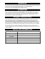
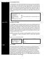
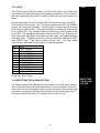
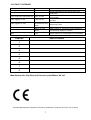
USER
MANUAL
CEF AP28 CONTROL PANEL
AP28
WARNINGS
This product has mains voltage present within the housing. Please take the necessary
precautions in not allowing any liquid to spill on or into the housing.
There are no user serviceable parts inside this product.
STANDARDS
This unit conforms to EMC directive 89/336/EEC & LVD 73/23/EEC. This unit has
been tested to the required standards for emission, immunity and LVD regulations as
set out by the EU. This unit conforms to the requirements of BS4737 part 1 1986
which relates to security control equipment.
PRODUCT DESCRIPTION
The Control panel is an 8 zone programmable microprocessor control panel using
state of the art technology and building techniques. The Control panel has many
advanced features that can only be found in more expensive control panels. There are
many options in the programming functions to allow the control panel to be versatile
and user friendly. This allows the Control panel to be the ideal choice of your installer.
This product has been carefully designed and tested to give many reliable years of
service. Please make sure the Control panel is regularly serviced at least once a year
by your installer.
INSTALLER INFORMATION
NAME
COMPANY
INSTALLATION DATE
TELEPHONE
FAX
MOBILE
OTHER INFORMATION
1
1:0 SETTING THE SYSTEM
SETTING THE
SYSTEM
To arm the system enter your user code. The exit tone from any
extension speakers will sound at a low level, the keypad buzzer will
also sound. Any pulsed tones should return to a continuous tone
once you have left the building and the sensors have cleared. The
control panel arms after the exit timer has run out, at this point the
tone should cease. If for any reason the tone does not go continuous
after all the sensors have cleared, return to the keypad and press the
# key to abort the setting procedure. If the internal sounder activates
after the timer has expired, return to the keypad and enter your user
code and press #. Now refer to fault clearing. (section 14:0)
1:1 Selecting Full Set
FULL SET
Enter user code, no further action is required, leave the premises by
the authorised exit route.
1:2 Selecting Night Set
NIGHT SET
Enter user code then press * then 0. The zones pre-programmed to
be isolated will start to flash. The extension speaker sounds can be
removed by the installer, if this is the case the extension sounder
may stop as soon as night set is selected. If the installer has
programmed instant night set the system arms as soon as the
selection is made.
1:3 HOME SET
HOME SET
Enter user code then press * then 8. This isolates any zones
programmed for isolation. Please note that this setting method will
allow the isolation of ALL entry routes including zone 1 (if enabled by
the installer). Follow the paragraph 1:0 for guidance regarding exit
tones etc.
2:0. MANUAL ISOLATION OF ALARM ZONES .
There may be occasions when you need to isolate additional zones.
Arm the system as above, then press * then the zone number you
want to isolate. That zone will flash indicating a successful isolation,
if you want more zones isolated press * and another zone. If any
zone is barred from isolation an error tone will be emitted.
Zones that cannot be isolated
•
Fire
•
PA
•
Tamper
•
Zone 1 in Full Set
•
Zone 8
2
ZONE
ISOLATION
DISARMING
3:0 DISARMING THE SYSTEM
Enter the protected area by the authorised entry route, a single
continuous tone will be heard from any extension speaker and from
keypads. Proceed directly to the keypad and enter your user code, the
system will disarm. If the entry tone from the speaker changes to rapid
pips then you have less than 10 seconds to disarm the system.
DISARMING
AFTER AN
ALARM
4:0 DISARMING AFTER AN ALARM
4:0:1 AFTER THE PANEL HAS AUTO RESET
Enter the protected area by the authorised entry route, an
intermittent tone will be heard from any extension speaker, proceed
directly to keypad and enter your user code, the system will disarm,
the zone/s will light on the control panel to indicate the cause of the
alarm, refer to panel reset section 13:0 to clear the panel.
The first to alarm will show a constantly illuminated light.
Subsequent alarms are shown as fast flashing lights.
Zones that were isolated are shown as slow flashing lights.
WHILE PANEL
IS IN ALARM
4:0:2 WHILE PANEL IS IN ALARM
Go directly to the keypad and insert your user code, the system will
disarm, the zone/s will light on the control panel to indicate the
cause of the alarm, refer to panel reset to clear.(section12:0)
The lights follow the same descriptions as above in section 4:0:1.
5:0 TAMPER FAULTS
TAMPER
The control panel is equipped with a common tamper circuit giving
protection from unauthorised handling. If the tamper circuit is broken
during any unset period the internal sounder will trigger and the tamper
light will illuminate. Proceed directly to the keypad and enter your user
code, the internal sounder will stop and revert to a low two tone sound.
Press the # key the panel will reset, if the tamper light continues to flash
then the cause of the tamper condition is still present. Refer to fault
clearing.(section 13:0)
PERSONAL
ATTACK
6:0 PERSONAL ATTACK
If your system has a personal attack button fitted this will be linked into
the alarm system as a 24hr device. This means the PA button will be live
all the time. If the PA is pressed all the sounders will operate and bring up
the zone light programmed as PA. Proceed directly to the keypad and
enter your user code, the sounders will stop and revert to a low two tone
sound. Press the # key the panel will reset, if the zone light continues to
flash then the cause for the personal attack condition is still present. Go to
the personal attack button(s) and reset with the special key provided, the
zone light should go out. If the light continues to flash refer to fault
clearing. (section 14:0)
Note: If the panel is armed and a PA is activated, you will need to disarm
the system as explained in section 4
3
6:0:1 PERSONAL ATTACK FROM REMOTE KEYPAD
If the installer has programmed personal attack on the keypads, pressing
and holding the * & # keys together for 3 seconds activates the system as
in 6:0. The only difference is that the tamper light will illuminate. Enter the
user code, the sounders will stop and revert to a low two tone sound.
Press the # key and the panel will reset.
PERSONAL
ATTACK FROM
REMOTE
KEYPAD
7:0 FIRE
FIRE
The installer may have linked smoke detectors to the control panel. If so
the sounder will give a loud whooping sound and the external sounder will
pulse at 2 second intervals. When the panel is set, the external sounder
constantly sounds. Make sure that every one exits the premises. When
you are sure that it is safe to return back, proceed directly to keypad enter
the user code. The sounders will stop and revert to a low two tone sound.
Press the # key the panel will reset.
USER FUNCTIONS & OPTIONS
8:0 CODE CHANGE
CODE CHANGE
There maybe times that you need to change your user code. The system
has 2 user codes. To help you remember your new code, write it down
before changing it and after you have successfully changed and
memorised the code destroy the written code. Remember, try not to use
obvious codes such as the current year. To change user code 1 enter
your existing user 1 code then press *, then 9 then 1. Four lights will
illuminate, enter your new 4 digit code. For every digit pressed of your
new code, one light will extinguish. Once your new code is entered the
panel will give you an accept tone, if the panel does not accept your code
then you may be in conflict with user code 2 or the engineering code, the
panel will abort the code change and retain your old code. Try again with
a different code. Check your new code is functioning correctly by
performing a full or night set then abort by pressing #.
To change user 2 code go through the above procedure but press *, then
9 then 2.
Panel Default Code is 1,2,3,4 for user 1 code. User 2 code is disabled by
default.
User code access levels.
•
•
•
•
User 1 code can alter both user codes.
User 1 code can disable user 2 code. (To disable user 2 code
changed user 2 code to 0000)
User 2 code has the same setting rights as the user 1 code
User 2 code cannot alter the user 1 code
If for any reason you loose your code or mistype in a code when changing
it, the installer will need to be contacted to default the panel codes.
4
CODE ACCESS
LEVELS
SOUNDER TEST 9:0 SOUNDER TESTS
It is advisable to check that the sounders are working correctly periodically.
To do this go to a keypad, enter a user code then press * then 9, each of
the tests lasts for 5 seconds. All the lights on the control panel will
illuminate, and the system tests start. The lights will go out and the internal
sounder will activate (proceed outside where the external sounder is
fitted). The external sounder will trigger then the external strobe will flash
(if fitted and enabled) and then the panel will clear down. The test is now
complete.
QUICK CHECK
Enter code then, *, 9 .
All lights on.
Internal sounder.
External Sounder.
Strobe.
Test Ended Panel clears.
}
WALK TEST
EACH CONDITION IN 5 SECOND INTERVALS
10:0 WALK TESTING
It is advisable to check that the detection devices are communicating with
the panel. This kind of testing should be performed every 3 months. To do
this go to the keypad enter a user code, then press *, then 9 and 4. When
any detector is activated or a door fitted with a contact is opened, the
internal sounder will give a loud pulsing tone and the zone light will
illuminate. Clear the detector or close the door and the sound will revert
back to a continuous sound, proceed to the next device until you have
completed testing all the zones.
NOTE: The zone LED’s will stay on at the keypad until the tests have been
completed to allow confirmation that all zones have operated
correctly.
press * to exit the walk test mode.
Quick check
Enter code then, *, 9 ,4
Walk test the zones
Press * to finish
CHIME
Zones that cannot be walk Tested are:
Fire
PA
Tamper
11:0. CHIME.
The control panel offers the ability to have chime on a zone when unset.
This feature will emit a chime tone via the extension speaker whenever a
zone is activated. To achieve this press the * key and the number key that
represents the zone(s) you want on chime. The light for the zone will
illuminate. Press * to accept the zones on chime. To remove a zone on
chime press the * key and the zones will light up that are currently active.
Press the key that represents the zone, the light will go out, chime is now
disabled on that zone. Press * key to finish. This feature is only active on
zones enabled by your installer.
5
12:0 LOGS
LOGS
The Control panel has the ability to look at the last 9 set and unset
conditions of the panel as well as the last alarm conditions. This is useful if
the panel has been reset and you need to find the zone that caused the
alarm.
Enter a user code, the exit tone will start, then press the * key then 9, 3.
The log starts viewing Day 1 set. The log is organised as SET and UNSET
events. All events are recorded. The first alarm is shown by the relevant
LED being lit continuously. Subsequent alarms are shown by a fast pulse
of the zone LED. Any isolated zones are shown by a slow pulse of the
zone LED. The buzzer sounds whilst viewing the SET logs. Pressing the
0 key shows the last alarm event that occurred, even if the panel has been
set many times. Pressing the # key changes between viewing the SET
and UNSET logs. This may be done at any time. The log review
automatically ends after15 seconds if no keys are pressed.
KEY
0
1
2
3
4
5
6
7
8
9
#
VIEW
LAST ALARM
LOG EVENT 1
LOG EVENT 2
LOG EVENT 3
LOG EVENT 4
LOG EVENT 5
LOG EVENT 6
LOG EVENT 7
LOG EVENT 8
LOG EVENT 9
SET / UNSET
Press the * key to finish.
13:0 RESETTING THE ALARM SYSTEM
If the alarm system has activated you will need to reset the panel, make a
note of the zone that caused the activation for future reference. Enter the
user code, the internal sounder will give a low two tone sound, press the #
key and an accept tone will be given and the activated zone light will go
out and the panel will reset. The system is now ready for use.
6
RESETTING
THE ALARM
SYSTEM
14:0 FAULT CLEARING
SYMPTOM
Zone light on continuous in day
CAUSE
Alarm activated
Tone pulsing on exit
Zone in Fault
Tone continues to pulse after exit
Zone in Fault
Alarm triggers on exit
Timer ran out
Alarm triggers on entry
Tamper light continues to flash
No Mains Light
Panel appears dead (no mains
light)
Timer ran out,
deviated from entry
route.
Tamper fault
Mains off, fuse
blown
battery not taking
over
ZONE No
ACTION
Do a panel reset
Leave protected area and wait for tone to go
continuous.
Check for open doors, or a detector is in fault, call
your installer
Go quicker to exit or call your installer to extend
exit time
Follow entry procedure, call your installer to
extend entry time
Call Installer
Switch mains on, check other mains appliances,
call electricity supplier or installer
Check mains is on. Call installer to check battery.
AREA COVERED
1
2
3
4
5
6
7
8
Manufactured for City Electrical Factors by IntelliSense UK Ltd.
Printed & Manufactured in Republic of China by IntelliSense. Document No F-051-175-01 Rev B
7