1
Optima IGS 320, Optima IGS 330
Conformance Statement of DICOM
OPERATING DOCUMENTATION
5537565-1-8EN
Revision 1
Optima IGS 320, Optima IGS 330 Conformance Statement of DICOM
Direction 5537565-1-8EN, Revision 1
2
Optima IGS 320, Optima IGS 330 Conformance Statement of DICOM
Direction 5537565-1-8EN, Revision 1
Important Information
LANGUAGE
ПРЕДУПРЕЖДЕНИЕ Това упътване за работа е налично само на английски език.
(BG)
• Ако доставчикът на услугата на клиента изиска друг език, задължение на
клиента е да осигури превод.
警告
(ZH-CN)
警告
(ZH-HK)
警告
(ZH-TW)
UPOZORENJE
(HR)
Important Information
•
Не използвайте оборудването, преди да сте се консултирали и разбрали
упътването за работа.
•
Неспазването на това предупреждение може да доведе до нараняване на
доставчика на услугата, оператора или пациентa в резултат на токов удар,
механична или друга опасност.
本维修手册仅提供英文版本。
• 如果客户的维修服务人员需要非英文版本,则客户需自行提供翻译服务。
•
未详细阅读和完全理解本维修手册之前,不得进行维修。
•
忽略本警告可能对维修服务人员、操作人员或患者造成电击、机械伤害或其他形式的
伤 害。
本服務手冊僅提供英文版本。
• 倘若客戶的服務供應商需要英文以外之服務手冊,客戶有責任提供翻譯服務。
•
除非已參閱本服務手冊及明白其內容,否則切勿嘗試維修設備。
•
不遵從本警告或會令服務供應商、網絡供應商或病人受到觸電、機械性或其他的危
險。
本維修手冊僅有英文版。
• 若客戶的維修廠商需要英文版以外的語言,應由客戶自行提供翻譯服務。
•
請勿試圖維修本設備,除非 您已查閱並瞭解本維修手冊。
•
若未留意本警告,可能導致維修廠商、操作員或病患因觸電、機械或其他危險而受
傷。
Ovaj servisni priručnik dostupan je na engleskom jeziku.
• Ako davatelj usluge klijenta treba neki drugi jezik, klijent je dužan osigurati prijevod.
•
Ne pokušavajte servisirati opremu ako niste u potpunosti pročitali i razumjeli ovaj
servisni priručnik.
•
Zanemarite li ovo upozorenje, može doći do ozljede davatelja usluge, operatera ili
pacijenta uslijed strujnog udara, mehaničkih ili drugih rizika.
3
Optima IGS 320, Optima IGS 330 Conformance Statement of DICOM
Direction 5537565-1-8EN, Revision 1
VÝSTRAHA
(CS)
ADVARSEL
(DA)
WAARSCHUWING
(NL)
WARNING
(EN)
HOIATUS
(ET)
4
Tento provozní návod existuje pouze v anglickém jazyce.
• V případě, že externí služba zákazníkům potřebuje návod v jiném jazyce, je zajiště‐
ní překladu do odpovídajícího jazyka úkolem zákazníka.
•
Nesnažte se o údržbu tohoto zařízení, aniž byste si přečetli tento provozní návod a
pochopili jeho obsah.
•
V případě nedodržování této výstrahy může dojít k poranění pracovníka prodejního
servisu, obslužného personálu nebo pacientů vlivem elektrického proudu, respektive
vlivem mechanických či jiných rizik.
Denne servicemanual findes kun på engelsk.
Hvis en kundes tekniker har brug for et andet sprog end engelsk, er det kundens
ansvar at sørge for oversættelse.
•
•
Forsøg ikke at servicere udstyret uden at læse og forstå denne servicemanual.
•
Manglende overholdelse af denne advarsel kan medføre skade på grund af elektrisk
stød, mekanisk eller anden fare for teknikeren, operatøren eller patienten.
Deze onderhoudshandleiding is enkel in het Engels verkrijgbaar.
• Als het onderhoudspersoneel een andere taal vereist, dan is de klant verantwoorde‐
lijk voor de vertaling ervan.
•
Probeer de apparatuur niet te onderhouden alvorens deze onderhoudshandleiding
werd geraadpleegd en begrepen is.
•
Indien deze waarschuwing niet wordt opgevolgd, zou het onderhoudspersoneel, de
operator of een patiënt gewond kunnen raken als gevolg van een elektrische schok,
mechanische of andere gevaren.
This service manual is available in English only.
If a customer's service provider requires a language other than English, it is the cus‐
tomer's responsibility to provide translation services.
•
•
Do not attempt to service the equipment unless this service manual has been con‐
sulted and is understood.
•
Failure to heed this warning may result in injury to the service provider, operator or
patient from electric shock, mechanical or other hazards.
See teenindusjuhend on saadaval ainult inglise keeles.
• Kui klienditeeninduse osutaja nõuab juhendit inglise keelest erinevas keeles, vastu‐
tab klient tõlketeenuse osutamise eest.
•
Ärge üritage seadmeid teenindada enne eelnevalt käesoleva teenindusjuhendiga
tutvumist ja sellest aru saamist.
•
Käesoleva hoiatuse eiramine võib põhjustada teenuseosutaja, operaatori või pat‐
siendi vigastamist elektrilöögi, mehaanilise või muu ohu tagajärjel.
Important Information
Optima IGS 320, Optima IGS 330 Conformance Statement of DICOM
Direction 5537565-1-8EN, Revision 1
VAROITUS
(FI)
ATTENTION
(FR)
WARNUNG
(DE)
ΠΡΟΕΙΔΟΠΟΙΗΣΗ
(EL)
FIGYELMEZTETÉS
(HU)
Important Information
Tämä huolto-ohje on saatavilla vain englanniksi.
• Jos asiakkaan huoltohenkilöstö vaatii muuta kuin englanninkielistä materiaalia, tar‐
vittavan käännöksen hankkiminen on asiakkaan vastuulla.
•
Älä yritä korjata laitteistoa ennen kuin olet varmasti lukenut ja ymmärtänyt tämän
huolto-ohjeen.
•
Mikäli tätä varoitusta ei noudateta, seurauksena voi olla huoltohenkilöstön, laitteis‐
ton käyttäjän tai potilaan vahingoittuminen sähköiskun, mekaanisen vian tai muun
vaaratilanteen vuoksi.
Ce manuel d’installation et de maintenance est disponible uniquement en anglais.
Si le technicien d'un client a besoin de ce manuel dans une langue autre que l'an‐
glais, il incombe au client de le faire traduire.
•
•
Ne pas tenter d'intervenir sur les équipements tant que ce manuel d’installation et
de maintenance n'a pas été consulté et compris.
•
Le non-respect de cet avertissement peut entraîner chez le technicien, l'opérateur
ou le patient des blessures dues à des dangers électriques, mécaniques ou autres.
Diese Serviceanleitung existiert nur in englischer Sprache.
Falls ein fremder Kundendienst eine andere Sprache benötigt, ist es Aufgabe des
Kunden für eine entsprechende Übersetzung zu sorgen.
•
•
Versuchen Sie nicht diese Anlage zu warten, ohne diese Serviceanleitung gelesen
und verstanden zu haben.
•
Wird diese Warnung nicht beachtet, so kann es zu Verletzungen des Kundendienst‐
technikers, des Bedieners oder des Patienten durch Stromschläge, mechanische
oder sonstige Gefahren kommen.
Το παρόν εγχειρίδιο σέρβις διατίθεται μόνο στα αγγλικά.
• Εάν ο τεχνικός σέρβις ενός πελάτη απαιτεί το παρόν εγχειρίδιο σε γλώσσα εκτός των
αγγλικών, αποτελεί ευθύνη του πελάτη να παρέχει τις υπηρεσίες μετάφρασης.
•
Μην επιχειρήσετε την εκτέλεση εργασιών σέρβις στον εξοπλισμό αν δεν έχετε
συμβουλευτεί και κατανοήσει το παρόν εγχειρίδιο σέρβις.
•
Αν δεν προσέξετε την προειδοποίηση αυτή, ενδέχεται να προκληθεί τραυματισμός
στον τεχνικό σέρβις, στο χειριστή ή στον ασθενή από ηλεκτροπληξία, μηχανικούς ή
άλλους κινδύνους.
Ezen karbantartási kézikönyv kizárólag angol nyelven érhető el.
• Ha a vevő szolgáltatója angoltól eltérő nyelvre tart igényt, akkor a vevő felelőssége
a fordítás elkészíttetése.
•
Ne próbálja elkezdeni használni a berendezést, amíg a karbantartási kézikönyvben
leírtakat nem értelmezték.
•
Ezen figyelmeztetés figyelmen kívül hagyása a szolgáltató, működtető vagy a beteg
áramütés, mechanikai vagy egyéb veszélyhelyzet miatti sérülését eredményezheti.
5
Optima IGS 320, Optima IGS 330 Conformance Statement of DICOM
Direction 5537565-1-8EN, Revision 1
AÐVÖRUN
(IS)
AVVERTENZA
(IT)
警告
(JA)
경고
(KO)
BRĪDINĀJUMS
(LV)
6
Þessi þjónustuhandbók er aðeins fáanleg á ensku.
• Ef að þjónustuveitandi viðskiptamanns þarfnast annas tungumáls en ensku, er það
skylda viðskiptamanns að skaffa tungumálaþjónustu.
•
Reynið ekki að afgreiða tækið nema að þessi þjónustuhandbók hefur verið skoðuð
og skilin.
•
Brot á sinna þessari aðvörun getur leitt til meiðsla á þjónustuveitanda, stjórnanda
eða sjúklings frá raflosti, vélrænu eða öðrum áhættum.
Il presente manuale di manutenzione è disponibile soltanto in lingua inglese.
Se un addetto alla manutenzione richiede il manuale in una lingua diversa, il cliente
è tenuto a provvedere direttamente alla traduzione.
•
•
Procedere alla manutenzione dell'apparecchiatura solo dopo aver consultato il pre‐
sente manuale ed averne compreso il contenuto.
•
Il mancato rispetto della presente avvertenza potrebbe causare lesioni all'addetto al‐
la manutenzione, all'operatore o ai pazienti provocate da scosse elettriche, urti mec‐
canici o altri rischi.
このサービスマニュアルには英語版しかありません。
• サービスを担当される業者が英語以外の言語を要求される場合、翻訳作業はその業
者の責任で行うものとさせていただきます。
•
このサービスマニュアルを熟読し理解せずに、装置のサービスを行わないでくださ
い。
•
この警告に従わない場合、サービスを担当される方、操作員あるいは患者 さんが、
感電や機械的又はその他の危険により負傷する可能性があります。
본 서비스 매뉴얼은 영어로만 이용하실 수 있습니다.
• 고객의 서비스 제공자가 영어 이외의 언어를 요구할 경우, 번역 서비스를 제공하는
것은 고객의 책임입니다.
•
본 서비스 매뉴얼을 참조하여 숙지하지 않은 이상 해당 장비를 수리하려고 시도하지
마십시오.
•
본 경고 사항에 유의하지 않으면 전기 쇼크, 기계적 위험, 또는 기타 위험으로 인해 서
비스 제공자, 사용자 또는 환자에게 부상을 입힐 수 있습니다.
Šī apkopes rokasgrāmata ir pieejama tikai angļu valodā.
• Ja klienta apkopes sniedzējam nepieciešama informācija citā valodā, klienta pienā‐
kums ir nodrošināt tulkojumu.
•
Neveiciet aprīkojuma apkopi bez apkopes rokasgrāmatas izlasīšanas un sapraša‐
nas.
•
Šī brīdinājuma neievērošanas rezultātā var rasties elektriskās strāvas trieciena, me‐
hānisku vai citu faktoru izraisītu traumu risks apkopes sniedzējam, operatoram vai
pacientam.
Important Information
Optima IGS 320, Optima IGS 330 Conformance Statement of DICOM
Direction 5537565-1-8EN, Revision 1
ĮSPĖJIMAS
(LT)
ADVARSEL
(NO)
OSTRZEŻENIE
(PL)
ATENÇÃO
(PT-BR)
ATENÇÃO
(PT-PT)
Important Information
Šis eksploatavimo vadovas yra tik anglų kalba.
• Jei kliento paslaugų tiekėjas reikalauja vadovo kita kalba – ne anglų, suteikti vertimo
paslaugas privalo klientas.
•
Nemėginkite atlikti įrangos techninės priežiūros, jei neperskaitėte ar nesupratote šio
eksploatavimo vadovo.
•
Jei nepaisysite šio įspėjimo, galimi paslaugų tiekėjo, operatoriaus ar paciento suža‐
lojimai dėl elektros šoko, mechaninių ar kitų pavojų.
Denne servicehåndboken finnes bare på engelsk.
Hvis kundens serviceleverandør har bruk for et annet språk, er det kundens ansvar
å sørge for oversettelse.
•
•
Ikke forsøk å reparere utstyret uten at denne servicehåndboken er lest og forstått.
•
Manglende hensyn til denne advarselen kan føre til at serviceleverandøren, oper‐
atøren eller pasienten skades på grunn av elektrisk støt, mekaniske eller andre
farer.
Niniejszy podręcznik serwisowy dostępny jest jedynie w języku angielskim.
• Jeśli serwisant klienta wymaga języka innego niż angielski, zapewnienie usługi tłu‐
maczenia jest obowiązkiem klienta.
•
Nie próbować serwisować urządzenia bez zapoznania się z niniejszym podręczni‐
kiem serwisowym i zrozumienia go.
•
Niezastosowanie się do tego ostrzeżenia może doprowadzić do obrażeń serwisan‐
ta, operatora lub pacjenta w wyniku porażenia prądem elektrycznym, zagrożenia
mechanicznego bądź innego.
Este manual de assistência técnica encontra-se disponível unicamente em inglês.
• Se outro serviço de assistência técnica solicitar a tradução deste manual, caberá ao
cliente fornecer os serviços de tradução.
•
Não tente reparar o equipamento sem ter consultado e compreendido este manual
de assistência técnica.
•
A não observância deste aviso pode ocasionar ferimentos no técnico, operador ou
paciente decorrentes de choques elétricos, mecânicos ou outros.
Este manual de assistência técnica só se encontra disponível em inglês.
• Se qualquer outro serviço de assistência técnica solicitar este manual noutro idio‐
ma, é da responsabilidade do cliente fornecer os serviços de tradução.
•
Não tente reparar o equipamento sem ter consultado e compreendido este manual
de assistência técnica.
•
O não cumprimento deste aviso pode colocar em perigo a segurança do técnico, do
operador ou do paciente devido a choques eléctricos, mecânicos ou outros.
7
Optima IGS 320, Optima IGS 330 Conformance Statement of DICOM
Direction 5537565-1-8EN, Revision 1
ATENŢIE
(RO)
ОСТОРОЖНО!
(RU)
UPOZORENJE
(SR)
UPOZORNENIE
(SK)
ATENCION
(ES)
8
Acest manual de service este disponibil doar în limba engleză.
• Dacă un furnizor de servicii pentru clienţi necesită o altă limbă decât cea engleză,
este de datoria clientului să furnizeze o traducere.
•
Nu încercaţi să reparaţi echipamentul decât ulterior consultării şi înţelegerii acestui
manual de service.
•
Ignorarea acestui avertisment ar putea duce la rănirea depanatorului, operatorului
sau pacientului în urma pericolelor de electrocutare, mecanice sau de altă natură.
Данное руководство по техническому обслуживанию представлено только на
английском языке.
• Если сервисному персоналу клиента необходимо руководство не на
английском, а на каком-то другом языке, клиенту следует самостоятельно
обеспечить перевод.
•
Перед техническим обслуживанием оборудования обязательно обратитесь к
данному руководству и поймите изложенные в нем сведения.
•
Несоблюдение требований данного предупреждения может привести к тому,
что специалист по техобслуживанию, оператор или пациент получит удар
электрическим током, механическую травму или другое повреждение.
Ovo servisno uputstvo je dostupno samo na engleskom jeziku.
Ako klijentov serviser zahteva neki drugi jezik, klijent je dužan da obezbedi prevodi‐
lačke usluge.
•
•
Ne pokušavajte da opravite uređaj ako niste pročitali i razumeli ovo servisno uputst‐
vo.
•
Zanemarivanje ovog upozorenja može dovesti do povređivanja servisera, rukovaoca
ili pacijenta usled strujnog udara ili mehaničkih i drugih opasnosti.
Tento návod na obsluhu je k dispozícii len v angličtine.
• Ak zákazníkov poskytovateľ služieb vyžaduje iný jazyk ako angličtinu, poskytnutie
prekladateľských služieb je zodpovednosťou zákazníka.
•
Nepokúšajte sa o obsluhu zariadenia, kým si neprečítate návod na obluhu a nepor‐
ozumiete mu.
•
Zanedbanie tohto upozornenia môže spôsobiť zranenie poskytovateľa služieb, ob‐
sluhujúcej osoby alebo pacienta elektrickým prúdom, mechanické alebo iné ohroze‐
nie.
Este manual de servicio sólo existe en inglés.
• Si el encargado de mantenimiento de un cliente necesita un idioma que no sea el
inglés, el cliente deberá encargarse de la traducción del manual.
•
No se deberá dar servicio técnico al equipo, sin haber consultado y comprendido
este manual de servicio.
•
La no observancia del presente aviso puede dar lugar a que el proveedor de servi‐
cios, el operador o el paciente sufran lesiones provocadas por causas eléctricas,
mecánicas o de otra naturaleza.
Important Information
Optima IGS 320, Optima IGS 330 Conformance Statement of DICOM
Direction 5537565-1-8EN, Revision 1
VARNING
(SV)
OPOZORILO
(SL)
DİKKAT
(TR)
Important Information
Den här servicehandboken finns bara tillgänglig på engelska.
• Om en kunds servicetekniker har behov av ett annat språk än engelska, ansvarar
kunden för att tillhandahålla översättningstjänster.
•
Försök inte utföra service på utrustningen om du inte har läst och förstår den här
servicehandboken.
•
Om du inte tar hänsyn till den här varningen kan det resultera i skador på servicete‐
knikern, operatören eller patienten till följd av elektriska stötar, mekaniska faror eller
andra faror.
Ta servisni priročnik je na voljo samo v angleškem jeziku.
• Če ponudnik storitve stranke potrebuje priročnik v drugem jeziku, mora stranka za‐
gotoviti prevod.
•
Ne poskušajte servisirati opreme, če tega priročnika niste v celoti prebrali in razu‐
meli.
•
Če tega opozorila ne upoštevate, se lahko zaradi električnega udara, mehanskih ali
drugih nevarnosti poškoduje ponudnik storitev, operater ali bolnik.
Bu servis kılavuzunun sadece ingilizcesi mevcuttur.
Eğer müşteri teknisyeni bu kılavuzu ingilizce dışında bir başka lisandan talep
ederse, bunu tercüme ettirmek müşteriye düşer.
•
•
Servis kılavuzunu okuyup anlamadan ekipmanlara müdahale etmeyiniz.
•
Bu uyarıya uyulmaması, elektrik, mekanik veya diğer tehlikelerden dolayı teknisyen,
operatör veya hastanın yaralanmasına yol açabilir.
9
Optima IGS 320, Optima IGS 330 Conformance Statement of DICOM
Direction 5537565-1-8EN, Revision 1
This page left intentionally blank.
10
Important Information
Optima IGS 320, Optima IGS 330 Conformance Statement of DICOM
Direction 5537565-1-8EN, Revision 1
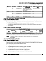
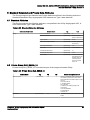
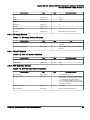
Revision History
Part / Rev
Date
5537565-1-8EN rev 1
April, 2015
Revision History
Reason for change
Initial release of 5537565-1-8EN
Pages
144
11
Optima IGS 320, Optima IGS 330 Conformance Statement of DICOM
Direction 5537565-1-8EN, Revision 1
This page left intentionally blank.
12
Revision History
Optima IGS 320, Optima IGS 330 Conformance Statement of DICOM
Direction 5537565-1-8EN, Revision 1
Table of Contents
Chapter 1 CONFORMANCE STATEMENT OVERVIEW.......................................................................21
1 Conformance Statement Overview................................................................................................21
Chapter 2 INTRODUCTION................................................................................................................... 23
1 Introduction....................................................................................................................................23
1.1 Overview...............................................................................................................................23
1.2 Quebec................................................................................................................................. 23
1.3 Overall Dicom Conformance Statement Document Structure.............................................. 23
1.4 Intended Audience................................................................................................................25
1.5 Scope and Field Application................................................................................................. 25
1.6 Important Remarks............................................................................................................... 25
1.7 References........................................................................................................................... 26
1.8 Definitions.............................................................................................................................26
1.9 Symbols and Abbreviations.................................................................................................. 28
Chapter 3 NETWORK CONFORMANCE STATEMENT........................................................................31
1 Introduction....................................................................................................................................31
2 Implementation Model................................................................................................................... 32
2.1 Application Data Flow Diagram............................................................................................ 32
2.2 Functional Definition of AE’s.................................................................................................33
2.3 Sequencing of Real–World Activities....................................................................................35
3 AE Specifications...........................................................................................................................36
3.1 Optima AE Specification.......................................................................................................36
3.2 Association Establishment Policies...................................................................................... 36
3.2.1 General........................................................................................................................36
3.2.2 Number of Associations...............................................................................................36
3.2.3 Asynchronous Nature.................................................................................................. 36
3.2.4 Implementation Identifying Information........................................................................36
3.3 Association Initiation Policy.................................................................................................. 37
3.3.1 Real–World Activity Copy Images and/or Dose SR’s ................................................. 37
Table of Contents
13
Optima IGS 320, Optima IGS 330 Conformance Statement of DICOM
Direction 5537565-1-8EN, Revision 1
3.3.1.1 Associated Real–World Activity ......................................................................... 37
3.3.1.2 Proposed Presentation Context Table................................................................37
3.3.2 Real–World Activity Verification Acknowledge.............................................................39
3.3.2.1 Associated Real–World Activity.......................................................................... 39
3.3.2.2 Proposed Presentation Context Table................................................................39
3.3.3 Real-World Activity Get Worklist..................................................................................39
3.3.3.1 Associated Real-World Activity...........................................................................39
3.3.3.2 Proposed Presentation Context Table................................................................40
3.3.4 Real-World Activity Request Storage Commitment..................................................... 41
3.3.4.1 Associated Real–World Activity.......................................................................... 41
3.3.4.2 Proposed Presentation Context Table................................................................41
3.3.5 Real-world Activity Send MPPS...................................................................................43
3.3.5.1 Associated Real-world Activity............................................................................43
3.3.5.2 Proposed Presentation context table..................................................................44
3.4 Association Acceptance Policy.............................................................................................44
3.4.1 Introduction.................................................................................................................. 44
3.4.2 Real-World Activity Verification Acknowledge............................................................. 45
3.4.2.1 Associated Real-World Activity...........................................................................45
3.4.2.2 Accepted Presentation Context Table................................................................ 45
3.4.3 Real–World Activity Request Storage Commitment.................................................... 45
3.4.3.1 Associated Real–World Activity.......................................................................... 45
3.4.3.2 Accepted Presentation Context Table................................................................ 45
4 Communication Profiles.................................................................................................................47
4.1 Supported Communication Stacks (PS 3.8)......................................................................... 47
4.2 OSI Stack............................................................................................................................. 47
4.3 TCP/IP Stack........................................................................................................................ 47
4.3.1 API...............................................................................................................................47
4.3.2 Physical Media Support............................................................................................... 47
4.4 Additional Protocol Support.................................................................................................. 47
4.5 IPv4 and IPv6 Support..........................................................................................................47
5 Extensions / Specializations / Privatizations................................................................................. 48
14
Table of Contents
Optima IGS 320, Optima IGS 330 Conformance Statement of DICOM
Direction 5537565-1-8EN, Revision 1
5.1 Standard Extended SOP Classes........................................................................................ 48
6 Configuration................................................................................................................................. 49
6.1 AE Title/Presentation Address Mapping...............................................................................49
6.2 Configurable Parameters......................................................................................................49
7 Support of Extended Character Sets.............................................................................................52
Chapter 4 X-RAY ANGIOGRAPHY (XA) INFORMATION OBJECT IMPLEMENTATION..................... 53
1 Introduction....................................................................................................................................53
2 Optima Mapping of DICOM Entities.............................................................................................. 54
3 IOD Module Table......................................................................................................................... 55
4 Information Module Definitions......................................................................................................57
4.1 Patient Entity Modules..........................................................................................................57
4.2 Study Entity Modules............................................................................................................58
4.2.1 General Study Module................................................................................................. 58
4.2.2 Patient Study Module...................................................................................................58
4.3 Series Entity Modules...........................................................................................................59
4.4 Equipment Entity Modules....................................................................................................61
4.5 Image Entity Modules........................................................................................................... 61
4.5.1 General Image Module................................................................................................ 61
4.5.2 Image Pixel Module..................................................................................................... 62
4.5.3 Contrast/Bolus Module................................................................................................ 62
4.5.4 Cine Module.................................................................................................................62
4.5.5 Multi–Frame Module.................................................................................................... 63
4.5.6 Frame Pointers Module............................................................................................... 63
4.5.7 Mask Module............................................................................................................... 63
4.5.8 Display Shutter Module................................................................................................64
4.5.9 X-Ray Image Module................................................................................................... 64
4.5.10 X-Ray Acquisition Module..........................................................................................64
4.5.11 X–Ray Collimator Module.......................................................................................... 65
4.5.12 X–Ray Table Module................................................................................................. 66
4.5.13 XA Positioner Module................................................................................................ 66
Table of Contents
15
Optima IGS 320, Optima IGS 330 Conformance Statement of DICOM
Direction 5537565-1-8EN, Revision 1
4.5.14 DX Detector Module.................................................................................................. 67
4.5.15 VOI LUT module........................................................................................................ 68
4.5.16 SOP Common Module...............................................................................................68
5 Standard Extended and Private Data Attributes............................................................................69
5.1 Standard Attributes...............................................................................................................69
5.2 Private Group DLX_SERIE_01............................................................................................. 69
5.3 Private Group GEMS_XR3DCAL_01....................................................................................71
5.4 Private Group GEMS_DL_IMG_01....................................................................................... 72
5.5 Private Group GEMS_DL_STUDY_01..................................................................................79
5.6 Private Group GEMS_DL_SERIES_01.................................................................................80
5.7 Private Group GEMS_DL_IMG_02....................................................................................... 80
Chapter 5 SC INFORMATION OBJECT IMPLEMENTATION............................................................... 81
1 Introduction....................................................................................................................................81
2 Optima Mapping of DICOM Entities.............................................................................................. 82
3 IOD Module Table......................................................................................................................... 83
4 Information Module Definitions......................................................................................................84
4.1 Patient Entity Modules..........................................................................................................84
4.2 Study Entity Modules............................................................................................................85
4.2.1 General Study Module................................................................................................. 85
4.2.2 Patient Study Module...................................................................................................85
4.3 Series Entity Modules...........................................................................................................86
4.4 Equipment Entity Modules....................................................................................................87
4.4.1 General Equipment Module......................................................................................... 87
4.4.2 SC Equipment Module.................................................................................................88
4.5 Image Entity Modules........................................................................................................... 88
4.5.1 General Image Module................................................................................................ 88
4.5.2 Image Pixel Module..................................................................................................... 88
4.5.3 SC Image Module........................................................................................................ 89
4.5.4 VOI LUT module.......................................................................................................... 89
4.5.5 SOP Common Module.................................................................................................89
16
Table of Contents
Optima IGS 320, Optima IGS 330 Conformance Statement of DICOM
Direction 5537565-1-8EN, Revision 1
5 Standard Extended and Private Data Attributes............................................................................90
5.1 Standard Attributes...............................................................................................................90
5.2 Private Group DLX_SERIE_01............................................................................................. 91
5.3 Private Group GEMS_DL_IMG_01....................................................................................... 92
5.4 Private Group GEMS_DL_STUDY_01..................................................................................95
5.5 Private Group GEMS_QVA_PHOTO_01.............................................................................. 96
5.6 Private Group QCA_RESULTS............................................................................................ 97
5.7 Private Group QUANTITATIVE_RESULTS..........................................................................98
5.8 Private Group GEMS_DL_SERIES_01.................................................................................99
Chapter 6 MODALITY WORKLIST INFORMATION MODEL DEFINITION......................................... 101
1 Introduction..................................................................................................................................101
2 Worklist Query Module Table...................................................................................................... 102
3 Worklist Query Module Definitions.............................................................................................. 103
3.1 Common Scheduled Procedure Step Entity Modules........................................................ 103
3.1.1 SOP Common Module...............................................................................................103
3.1.2 Scheduled Procedure Step Module........................................................................... 103
3.2 Common Requested Procedure Entity Modules................................................................ 104
3.3 Common Imaging Service Request Entity Modules........................................................... 104
3.4 Common visit Entity Modules............................................................................................. 105
3.5 Common Patient Entity Modules........................................................................................ 105
3.5.1 Patient Identification.................................................................................................. 105
3.5.2 Patient Demographic................................................................................................. 106
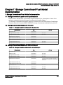
Chapter 7 STORAGE COMMITMENT PUSH MODEL IMPLEMENTATION....................................... 107
1 Storage Commitment Push Model Implementation.....................................................................107
1.1 Storage commitment push model implementation............................................................. 107
1.2 Storage Commitment Module for N-Action.........................................................................107
1.3 Storage Commitment Module for N-Event-Report..............................................................107
Chapter 8 MODALITY PERFORMED PROCEDURE STEP IMPLEMENTATION...............................109
1 Introduction..................................................................................................................................109
Table of Contents
17
Optima IGS 320, Optima IGS 330 Conformance Statement of DICOM
Direction 5537565-1-8EN, Revision 1
2 Relationship Between Scheduled and Performed Procedure Steps........................................... 110
3 Modality Performed Procedure Step Module Table.................................................................... 111
4 Modality Performed Procedure Step Module Definitions.............................................................112
4.1 SOP Common Module........................................................................................................112
4.2 Performed Procedure Step Relationship Module............................................................... 112
4.3 Performed Procedure Step Information Module................................................................. 113
4.4 Image Acquisition Result Module....................................................................................... 115
4.5 Radiation Dose Module...................................................................................................... 116
5 Billing and Material Management Codes Module........................................................................117
6 Standard Extended and Private Data Attributes..........................................................................118
6.1 Standard Attributes.............................................................................................................118
6.2 Private Group GEMS_DL_STUDY_01................................................................................118
6.3 Private Group GEMS_DLX_DOSE_01............................................................................... 119
Chapter 9 X-RAY RADIATION DOSE STRUCTURED REPORT INFORMATION OBJECT
IMPLEMENTATION...................................................................................................................... 121
1 Introduction..................................................................................................................................121
2 Optima Mapping of DICOM Entities............................................................................................ 122
3 IOD Module Table....................................................................................................................... 123
4 Information Module Definitions....................................................................................................124
4.1 Study Entity Modules..........................................................................................................124
4.2 Series Entity Modules.........................................................................................................124
4.3 Equipment Entity Modules..................................................................................................125
4.4 Document Entity Modules...................................................................................................125
4.4.1 SR Document General Module..................................................................................125
4.4.2 SR Document Content Module.................................................................................. 127
4.4.3 SOP Common Module...............................................................................................128
5 Standard Extended and Private Context Groups ....................................................................... 129
5.1 Standard Extended and Private Context Groups .............................................................. 129
5.2 Standard Extended Context Groups...................................................................................129
5.3 Private Context Groups...................................................................................................... 129
5.4 Configurable Context Groups............................................................................................. 130
18
Table of Contents
Optima IGS 320, Optima IGS 330 Conformance Statement of DICOM
Direction 5537565-1-8EN, Revision 1
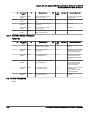
6 Standard, Standard Extended and Private Templates................................................................ 131
6.1 Standard Templates........................................................................................................... 131
6.1.1 Template ID 10001 X-Ray Radiation Dose................................................................131
6.1.2 TID 10002 Accumulated X-Ray Dose (Type: Extensible) .........................................132
6.1.3 TID 10003 Irradiation Event X-Ray Data (Type: Extensible) .................................... 133
6.1.4 TID 10004 Accumulated Projection X-Ray Dose (Type: Extensible) ........................139
6.1.5 TID 1002 Observer Context.......................................................................................140
6.1.6 TID 1003 Person Observer Identifying Attributes...................................................... 141
6.1.7 TID 1004 Device Observer Identifying Attributes.......................................................141
6.1.8 TID 1020 Person Participant......................................................................................141
6.1.9 TID 1021 Device Participant...................................................................................... 142
6.2 Private Templates...............................................................................................................142
Table of Contents
19
Optima IGS 320, Optima IGS 330 Conformance Statement of DICOM
Direction 5537565-1-8EN, Revision 1
This page left intentionally blank.
20
Table of Contents
Optima IGS 320, Optima IGS 330 Conformance Statement of DICOM
Direction 5537565-1-8EN, Revision 1
Chapter 1 Conformance Statement Overview
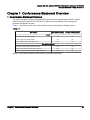
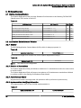
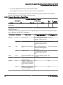
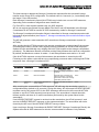
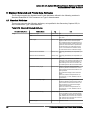
1 Conformance Statement Overview
The Optima system provides sophisticated image processing and storage functions. Optima
system will provide support for DICOM 3.0 to achieve interoperability across equipment
produced by different vendors.
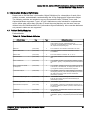
Table 1-1 provides an overview of the network services supported by Optima system.
Table 1-1:
SOP Classes
User of Service (SCU)
Provider of Service (SCP)
Secondary Capture Image Storage
Yes
No
X-Ray Angiographic Image Storage
Yes
No
X-Ray Radiation Dose SR Image Storage
Yes
No
Storage Commitment Push Model SOP Class
Yes*
No
Modality Performed Procedure Step SOP Class
Yes*
No
Modality Worklist Information Model – FIND SOP Class
Yes*
No
Transfer
Workflow Management
Option*: This means that this service can be purchased separately
Chapter 1 Conformance Statement Overview
21
Optima IGS 320, Optima IGS 330 Conformance Statement of DICOM
Direction 5537565-1-8EN, Revision 1
This page left intentionally blank.
22
1 Conformance Statement Overview
Optima IGS 320, Optima IGS 330 Conformance Statement of DICOM
Direction 5537565-1-8EN, Revision 1
Chapter 2 Introduction
1 Introduction
1.1 Overview
This DICOM Conformance Statement is divided into Chapters as described below:
•
Chapter 1 (Conformance Statement Overview), which describes the purpose of this
Conformance Statement.
•
Chapter 2 (Introduction), which describes the overall structure, intent, and references for this
Conformance Statement.
•
Chapter 3 (Network Conformance Statement), which specifies the GEMS equipment
compliance to the DICOM requirements for the implementation of Networking features.
•
Chapter 4 (X–Ray Angiography Information Object Implementation), which specifies the
GEMS equipment compliance to DICOM requirements for the implementation of a X–Ray
Angiography Information Object.
•
Chapter 5 (Secondary capture Information Object Implementation), which specifies the
GEMS equipment compliance to DICOM requirements for the implementation of a
Secondary capture Information Object.
•
Chapter 6 (Modality Worklist Information Model), which specifies the GEMS equipment
compliance to DICOM requirements for the implementation of the Modality Worklist service.
•
Chapter 7 (Storage Commitment Information Model Implementation), which specifies the
GEMS equipment compliance to DICOM requirements for the implementation of the Storage
Commitment service.
•
Chapter 8 (Modality Performed Procedure Step), which specifies the GEMS equipment
compliance to DICOM requirements for the implementation of a Modality Performed
Procedure Step Service.
•
Chapter 9 (X-ray Radiation Dose Structured Report), which specifies the GEMS equipment
compliance to DICOM requirements for the implementation of a X-ray Radiation Dose
Structured Report Object.
1.2 Quebec
GE Healthcare is "GE Santé" in Province of Quebec - Canada.
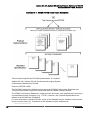
1.3 Overall Dicom Conformance Statement Document Structure
The Documentation Structure of the GEMS Conformance Statements and their relationship with
the DICOM Conformance Statements is shown in the Illustration below.
Chapter 2 Introduction
23
Optima IGS 320, Optima IGS 330 Conformance Statement of DICOM
Direction 5537565-1-8EN, Revision 1
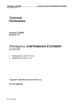
Illustration 2-1: GEMS DICOM Conformance Statements
This document specifies the DICOM implementation. It is entitled:
Optima IGS 320, Optima IGS 330 Cardiovascular Imaging System
Conformance Statement for DICOM
Direction 5537565-1-8EN
This DICOM Conformance Statement documents the DICOM Conformance Statement and
Technical Specification required to interoperate with the GEMS network interface.
The GEMS Conformance Statement, contained in this document, also specifies the Lower Layer
communications which it supports (e.g., TCP/IP). However, the Technical Specifications are
defined in the DICOM Part 8 standard.
For more information regarding DICOM, copies of the Standard may be obtained on the Internet
at http://medical.nema.org. Comments on the Standard may be addressed to:
24
1 Introduction
Optima IGS 320, Optima IGS 330 Conformance Statement of DICOM
Direction 5537565-1-8EN, Revision 1
DICOM Secretariat
NEMA
1300 N. 17th Street, Suite 1847
Rosslyn, VA 22209
USA
Phone: +1.703.841.3200
1.4 Intended Audience
The reader of this document is concerned with software design and/or system integration
issues. It is assumed that the reader of this document is familiar with the DICOM Standard and
with the terminology and concepts which are used in that Standard.
1.5 Scope and Field Application
It is the intent of this document to provide an unambiguous specification for GEMS
implementations. This specification, called a Conformance Statement, includes a DICOM
Conformance Statement and is necessary to ensure proper processing and interpretation of
GEMS medical data exchanged using DICOM. The GEMS Conformance Statements are
available to the public.
The reader of this DICOM Conformance Statement should be aware that different GEMS
devices are capable of using different Information Object Definitions. For example, a GEMS CT
Scanner may send images using the CT Information Object, MR Information Object, Secondary
Capture Object, etc.
Included in this DICOM Conformance Statement are the Module Definitions which define all
data elements used by this GEMS implementation. If the user encounters unspecified private
data elements while parsing a GEMS Data Set, the user is well advised to ignore those data
elements (per the DICOM standard). Unspecified private data element information is subject to
change without notice. If, however, the device is acting as a "full fidelity storage device", it
should retain and re-transmit all of the private data elements which are sent by GEMS devices.
1.6 Important Remarks
The use of these DICOM Conformance Statements, in conjunction with the DICOM Standards,
is intended to facilitate communication with GE imaging equipment. However, by itself, it is not
sufficient to ensure that inter–operation will be successful. The user (or user’s agent) needs to
proceed with caution and address at least four issues:
•
Integration – The integration of any device into an overall system of interconnected devices
goes beyond the scope of standards (DICOM v3.0), and of this introduction and associated
DICOM Conformance Statements when interoperability with non-GE equipment is desired.
The responsibility to analyze the applications requirements and to design a solution that
integrates GE imaging equipment with non–GE systems is the user's responsibility and
should not be underestimated. The user is strongly advised to ensure that such an
integration analysis is correctly performed.
•
Validation – Testing the complete range of possible interactions between any GE device and
non–GE devices, before the connection is declared operational, should not be overlooked.
Therefore, the user should ensure that any non–GE provider accepts full responsibility for all
validation required for their connection with GE devices. This includes the accuracy of the
Chapter 2 Introduction
25
Optima IGS 320, Optima IGS 330 Conformance Statement of DICOM
Direction 5537565-1-8EN, Revision 1
image data once it has crossed the interface between the GE imaging equipment and the
non–GE device and the stability of the image data for the intended applications.
Such a validation is required before any clinical use (diagnosis and/or treatment) is
performed. It applies when images acquired on GE imaging equipment are processed/
displayed on a non-GE device, as well as when images acquired on non-GE equipment is
processed/displayed on a GE console or workstation.
•
Future Evolution – GE understands that the DICOM Standard will evolve to meet the user's
growing requirements. GE is actively involved in the development of the DICOM Standard.
DICOM will incorporate new features and technologies and GE may follow the evolution of
the Standard. The GEMS protocol is based on DICOM as specified in each DICOM
Conformance Statement. Evolution of the Standard may require changes to devices which
have implemented DICOM. In addition, GE reserves the right to discontinue or make
changes to the support of communications features (on its products) described by these
DICOM Conformance Statements. The user should ensure that any non–GE provider, which
connects with GE devices, also plans for the future evolution of the DICOM Standard.
Failure to do so will likely result in the loss of function and/or connectivity as the DICOM
Standard changes and GE Products are enhanced to support these changes.
•
Interaction – It is the sole responsibility of the non–GE provider to ensure that
communication with the interfaced equipment does not cause degradation of GE imaging
equipment performance and/or function.
1.7 References
NEMA PS3:
Digital Imaging and Communications in Medicine (DICOM) Standard, available free at http://
medical.nema.org/.
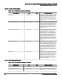
1.8 Definitions
Informal definitions are provided for the following terms used in this Conformance Statement.
The DICOM Standard is the authoritative source for formal definitons of these terms.
Abstract Syntax
The information agreed to be exchanged between applications, generally equivalent to a
Service/Object Pair (SOP) Class. Examples : Verification SOP Class, Modality Worklist
Information Model Find SOP Class, Computed Radiography Image Storage SOP Class.
Application Entity (AE)
An end point of a DICOM information exchange, including the DICOM network or media
interface software; i.e., the software that sends or receives DICOM information objects or
messages. A single device may have multiple Application Entities.
Application Entity Title
The externally known name of an Application Entity, used to identify a DICOM application to
other DICOM applications on the network.
Application Context
The specification of the type of communication used between Application Entities. Example:
DICOM network protocol.
26
1 Introduction
Optima IGS 320, Optima IGS 330 Conformance Statement of DICOM
Direction 5537565-1-8EN, Revision 1
Association
A network communication channel set up between Application Entities.
Attribute
A unit of information in an object definition; a data element identified by a tag. The information
may be a complex data structure (Sequence), itself composed of lower level data elements.
Examples: Patient ID (0010,0020), Accession Number (0008,0050), Photometric Interpretation
(0028,0004), Procedure Code Sequence (0008,1032).
Information Object Definition (IOD)
The specified set of Attributes that comprise a type of data object; does not represent a specific
instance of the data object, but rather a class of similar data objects that have the same
properties. The Attributes may be specified as Mandatory (Type 1), Required but possibly
unknown (Type 2), or Optional (Type 3), and there may be conditions associated with the use of
an Attribute (Types 1C and 2C). Examples: MR Image IOD, CT Image IOD, Print Job IOD.
Joint Photographic Experts Group (JPEG)
A set of standardized image compression techniques, available for use by DICOM applications.
Media Application Profile
The specification of DICOM information objects and encoding exchanged on removable media
(e.g., CDs).
Module
A set of Attributes within an Information Object Definition that are logically related to each other.
Example: Patient Module includes Patient Name, Patient ID, Patient Birth Date, and Patient
Sex.
Negotiation
First phase of Association establishment that allows Application Entities to agree on the types of
data to be exchanged and how that data will be encoded.
Presentation Context
The set of DICOM network services used over an Association, as negotiated between
Application Entities; includes Abstract Syntaxes and Transfer Syntaxes.
Protocol Data Unit (PDU)
A packet (piece) of a DICOM message sent across the network. Devices must specify the
maximum size packet they can receive for DICOM messages.
Security Profile
A set of mechanisms, such as encryption, user authentication, or digital signatures, used by an
Application Entity to ensure confidentiality, integrity, and/or availability of exchanged DICOM
data.
Service Class Provider (SCP)
Role of an Application Entity that provides a DICOM network service; typically, a server that
performs operations requested by another Application Entity (Service Class User). Examples:
Picture Archiving and Communication System (image storage SCP, and image query/retrieve
SCP), Radiology Information System (modality worklist SCP).
Chapter 2 Introduction
27
Optima IGS 320, Optima IGS 330 Conformance Statement of DICOM
Direction 5537565-1-8EN, Revision 1
Service Class User (SCU)
Role of an Application Entity that uses a DICOM network service; typically, a client. Examples:
imaging modality (image storage SCU, and modality worklist SCU), imaging workstation (image
query/retrieve SCU).
Service/Object Pair (SOP) Class
The specification of the network or media transfer (service) of a particular type of data (object);
the fundamental unit of DICOM interoperability specification. Examples: Ultrasound Image
Storage Service, Basic Grayscale Print Management.
Service/Object Pair (SOP) Instance
An information object; a specific occurrence of information exchanged in a SOP Class.
Examples: a specific x-ray image.
Tag
A 32-bit identifier for a data element, represented as a pair of four digit hexadecimal numbers,
the “group” and the “element”. If the “group” number is odd, the tag is for a private
(manufacturer-specific) data element. Examples: (0010,0020) [Patient ID], (07FE,0010) [Pixel
Data], (0019,0210) [private data element].
Transfer Syntax
The encoding used for exchange of DICOM information objects and messages. Examples:
JPEG compressed (images), little endian explicit value representation.
Unique Identifier (UID)
A globally unique “dotted decimal” string that identifies a specific object or a class of objects; an
ISO-8824 Object Identifier. Examples: Study Instance UID, SOP Class UID, SOP Instance UID.
Value Representation (VR)
The format type of an individual DICOM data element, such as text, an integer, a person’s
name, or a code. DICOM information objects can be transmitted with either explicit identification
of the type of each data element (Explicit VR), or without explicit identification (Implicit VR); with
Implicit VR, the receiving application must use a DICOM data dictionary to look up the format of
each data element.
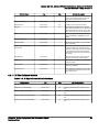
1.9 Symbols and Abbreviations
AE
Application Entity
AET
Application Entity Title
DICOM
Digital Imaging and Communications in Medicine
DPPS
Data Points Per Second
28
1 Introduction
Optima IGS 320, Optima IGS 330 Conformance Statement of DICOM
Direction 5537565-1-8EN, Revision 1
IOD
Information Object Definition
MWL
Modality Worklist
MPPS
Modality Performed Procedure Step
PACS
Picture Archiving and Communication System
SC
Secondary Capture
SCP
Service Class Provider
SCU
Service Class User
SOP
Service-Object Pair
SPS
Scheduled Procedure Step
SR
Structured Report
VR
Value Representation
VM
Value Multiplicity
XA
X-ray Angiography
Chapter 2 Introduction
29
Optima IGS 320, Optima IGS 330 Conformance Statement of DICOM
Direction 5537565-1-8EN, Revision 1
This page left intentionally blank.
30
1 Introduction
Optima IGS 320, Optima IGS 330 Conformance Statement of DICOM
Direction 5537565-1-8EN, Revision 1
Chapter 3 Network Conformance Statement
1 Introduction
This section of the DICOM Conformance Statement specifies the Optima product compliance to
DICOM requirements for Networking features.
This section details the roles and the DICOM Service Classes the System supports.
The Optima System DICOM implementation allows:
•
The user to copy Optima images and/or Radiation Structured Dose Reports acquired
through the system to a remote DICOM Application Entity, using the Standard Storage
DICOM Service as a Service Class User.
•
The user to request storage commitment for Optima images and/or Radiation Structured
Dose Reports that were previously sent trough the system to a remote DICOM application
entity, using the Storage Commitment Service as a Service Class User.
•
The user to check the application level communication from the Optima DICOM Server to a
remote DICOM Application Entity. To this aim the Optima System uses the Verification
DICOM Service Class as a Service Class User.
•
The user to get from the Radiology Information System (RIS) the list of procedure to be
performed. This is done using the Basic Worklist Management DICOM Service as a Service
Class User.
•
A remote Application Entity to check the application level communication with the Optima
System. This is done by providing the Verification DICOM Service Class as a Service Class
Provider.
•
To inform a remote DICOM Application Entity that a specific Procedure Step has been
started (using N-CREATE messages) and later that this Procedure Step has been
completed or discontinued (using N-SET messages). This is done by using the Modality
Performed Procedure Step service as a Service Class User.
Chapter 3 Network Conformance Statement
31
Optima IGS 320, Optima IGS 330 Conformance Statement of DICOM
Direction 5537565-1-8EN, Revision 1
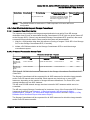
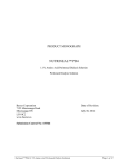
2 Implementation Model
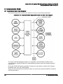
2.1 Application Data Flow Diagram
The network application model for the Optima is shown in the following Illustration:
Illustration 3-1: Optima Network Application Model and Data Flow Diagram
The Optima DICOM Application Entity is an application which handles DICOM protocol
communication. Optima DICOM AE is automatically brought up when the Optima system is
powered on.
All remote DICOM AE must be manually configured on the Optima, usually at the software
installation time, by a GE Field Engineer.
There are five local Real World activities which can cause the Optima DICOM AE to initiate a
DICOM association:
32
2 Implementation Model
Optima IGS 320, Optima IGS 330 Conformance Statement of DICOM
Direction 5537565-1-8EN, Revision 1
•
Copy Images/Dose SR,
•
Request Storage Commitment for a set of images and/or Dose SR’s,
•
Get Worklist,
•
Verification,
•
Provide MPPS.
Copy Image consists of an operator selecting one or several images through the User Interface
known as ”Browser” and ”Viewer”. Selection of Remote System and visualization of the transfer
status is done in a specific screen. The remote system can be any DICOM storage SCP
supporting XA modality.
Copy Dose SR consists of automatic Dose SR transactions generated by the system during the
termination of the exam. Also can be optionally transferred through the User Interface known as
“Browser”. Selection of Remote System and visualization of the transfer status is done in a
specific screen in Browser. The remote system can be any DICOM storage SCP supporting XRay Radiation Dose Structured Report Information Object.
Request storage commitment consists of an automatic request performed by the system after
each successful image transfer or after each successful Dose SR transfer to request Transfer of
Ownership for the Images and Dose SR’s that have been transferred earlier by the Copy Image/
Dose SR real world activity. The remote system shall be a DICOM Storage Commitment SCP.
Get Worklist activity consists of an operator request for the transfer of a list of procedure to be
performed on the Optima acquisition system from a remote HIS/RIS system. The Remote
system can be any DICOM modality worklist SCP.
Query keys can be entered for the following items:
•
Patient Name
•
Patient ID
•
Accession number
•
Procedure ID.
The system can be configured to query for its own modality (XA) or AE Title.
A date or a date range for the query can also be specified.
Verification consists of an operator request for the verification of the availability of a remote
station.
Provide MPPS Information entity consists of automatic MPPS transactions generated by the
system during the start and termination of the exam. Selection of Remote System and
visualization of the transfer status is done in a specific screen in Browser. The remote system
can be any DICOM SCP supporting MPPS.
2.2 Functional Definition of AE’s
The Optima DICOM Application Entity supports the following five SCU functions
1. Copy images/Dose SR’s:
Chapter 3 Network Conformance Statement
33
Optima IGS 320, Optima IGS 330 Conformance Statement of DICOM
Direction 5537565-1-8EN, Revision 1
○ Access to patient demographics, dose data and pixel Data in the local database
○ Build a DICOM Dataset
○ Initiate a DICOM Association to send the image(s) and/or Dose SR’s
○ Send Images and/or Dose SR’s
○ Close the association
2. Request Storage Commitment:
○ Initiate a DICOM Association in order to request Storage Commitment for the sent
image(s) and/or Dose SR’s.
○ Send the N–ACTION request.
○ Wait for the N–ACTION–RSP response.
○ Close the Association.
○ Receive N–EVENT–REPORT request in a separate association.
○ Send the N–EVENT–REPORT response.
○ Optionally, in the same association opened for N-ACTION request, the system can wait
for a configurable delay to receive the N–EVENT–REPORT request and send the NEVENT-REPORT response in the same association.
○ The system will accept a configurable number of DICOM associations from the Storage
Commitment SCP to receive storage commitment responses.
3. Get worklist:
○ Build a DICOM formatted basic worklist management data request
○ Initiate a DICOM Association to send the request
○ Wait for worklist response(s)
○ Access to the local database to add new patient / exam demographic data
○ Close the association
4. Verification:
○ Initiate a DICOM Association
○ Send the C–ECHO request
○ Wait for the C–ECHO response
○ Close the Association
5. Provide MPPS Information
34
2 Implementation Model
Optima IGS 320, Optima IGS 330 Conformance Statement of DICOM
Direction 5537565-1-8EN, Revision 1
○ User selects one MWL entry (scheduled case) [OR] User selects no MWL entry and
manually creates a patient (un-scheduled case) and starts the exam.
○ At the start of an exam, build a MPPS N-CREATE DICOM message.
○ Initiate a DICOM association to send the N-CREATE request.
○ Wait for the response.
○ Close the Association.
○ At the termination of the exam, build a MPPS N-SET DICOM message mentioning the
status as ‘COMPLETED’ or ‘DISCONTINUED’.
○ Initiate a DICOM association to send the N-SET request.
○ Wait for the response.
○ Close the Association.
The Optima DICOM Application Entity also serves a default SCP function, the Verification
Service Class, independently from others SCU functions.
2.3 Sequencing of Real–World Activities
Not Applicable.
Chapter 3 Network Conformance Statement
35
Optima IGS 320, Optima IGS 330 Conformance Statement of DICOM
Direction 5537565-1-8EN, Revision 1
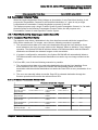
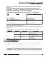
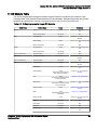
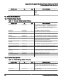
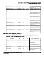
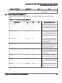
3 AE Specifications
3.1 Optima AE Specification
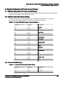
The Optima Application Entity provides Standard Conformance to the following DICOM SOP
Classes as an SCU and/or as an SCP:
Table 3-1:
SOP Class Name
SOP Class UID
SCU
SCP
Verification SOP Class
1.2.840.10008.1.1
Yes
Yes
Secondary Capture Image Storage
1.2.840.10008.5.1.4.1.1.7
Yes
No
X-Ray Angiographic Image Storage
1.2.840.10008.5.1.4.1.1.12.1
Yes
No
X-Ray Radiation Dose SR Image Storage
1.2.840.10008.5.1.4.1.1.88.67
Yes
No
Modality Worklist Information Model - FIND
1.2.840.10008.5.1.4.31
Yes
No
Modality Performed Procedure Step
1.2.840.10008.3.1.2.3.3
Yes
No
Storage Commitment Push Model
1.2.840.10008.1.20.1
Yes
No
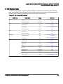
3.2 Association Establishment Policies
3.2.1 General
The DICOM Application Context Name (ACN), which is always proposed, is:
Table 3-2:
Application Context Name
1.2.840.10008.3.1.1.1
The maximum length PDU receive size for the Optima Application Entity is:
Table 3-3:
Maximum Length PDU
NOTE:
1024 Kbytes
This value is not configurable.
3.2.2 Number of Associations
The Optima Application Entity will initiate a maximum of 1 association at a time for each service
to remote nodes.
The Optima Application Entity will support a maximum of 5 simultaneous associations initiated
by remote nodes for the Storage Commitment Push Model.
3.2.3 Asynchronous Nature
Asynchronous mode is not supported. All operations will be performed synchronously.
3.2.4 Implementation Identifying Information
The Implementation UID for this DICOM Implementation is:
Table 3-4:
Optima Implementation UID
36
1.2.840.113619.6.364
3 AE Specifications
Optima IGS 320, Optima IGS 330 Conformance Statement of DICOM
Direction 5537565-1-8EN, Revision 1
Optima Implementation Version Name
Optima IGS 320, Optima IGS 330
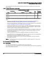
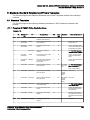
3.3 Association Initiation Policy
When the Optima Application Entity initiates an Association for any Real-World Activity, it will
propose the Presentation Contexts for all Real-World Activities; i.e., there is only a single,
comprehensive Presentation Context Negotiation proposed for the AE.
The Optima proposes only a single Transfer Syntax in each Presentation Context; i.e., for each
Abstract Syntax in the following Presentation Context Tables, the AE proposes one
Presentation Context for each specified Transfer Syntax.
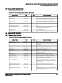
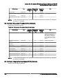
3.3.1 Real–World Activity Copy Images and/or Dose SR’s
3.3.1.1 Associated Real–World Activity
The operator must select a destination in the User Interface towards which the images/Dose
SR’s will be transferred. For Images, one of the two following scenarios is possible:
1. The operator selects data to be sent to the destination through the User Interface. Once
these selections are done, the user clicks on the “Network” button to initiate a “Copy images”
operation. The Optima DICOM AE will then initiate a DICOM association with the selected
destination and transfer the selected images on this association.
2. If system is configured for autoarchive, the Optima DICOM AE will automatically initiate a
DICOM association with the selected destination to transfer any new image created on the
system.
For Dose SR’s, one of the two following scenarios is possible:
1. The operator selects data to be sent to the destination through the User Interface. Once
these selections are done, Optima DICOM AE will automatically initiate a DICOM
association with the selected destination to transfer the Dose SR’s at every termination of an
exam.
2. The user can manually initiate to transfer Dose SR to selected destination through the
Browser operation and transfer the selected Dose SR’s.
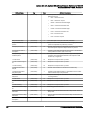
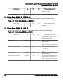
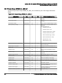
3.3.1.2 Proposed Presentation Context Table
Presentation Context Table – Proposed
Abstract Syntax
Name
Transfer Syntax
UID
Name List
Role
UID List
Extended Negotia‐
tion
Secondary Capture
Image Storage
1.2.840.10008.5.1.4.1.1.7
Implicit VR Little
Endian
1.2.840.10008.1.2
SCU
None
Secondary Capture
Image Storage
1.2.840.10008.5.1.4.1.1.7
Explicit VR Little
Endian
1.2.840.10008.1.2.1
SCU
None
X–Ray Angiographic
Image Storage
1.2.840.10008.5.1.4.1.1.12. Implicit VR Little
1
Endian
1.2.840.10008.1.2
SCU
None
X–Ray Angiographic
Image Storage
1.2.840.10008.5.1.4.1.1.12. Explicit VR Little
1
Endian
1.2.840.10008.1.2.1
SCU
None
X-Ray Radiation Dose
SR Image Storage
1.2.840.10008.5.1.4.1.1.88. Implicit VR Little
67
Endian
1.2.840.10008.1.2
SCU
None
Chapter 3 Network Conformance Statement
37
Optima IGS 320, Optima IGS 330 Conformance Statement of DICOM
Direction 5537565-1-8EN, Revision 1
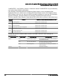
Presentation Context Table – Proposed
Abstract Syntax
Name
Transfer Syntax
UID
X-Ray Radiation Dose
SR Image Storage
Name List
1.2.840.10008.5.1.4.1.1.88. Explicit VR Little
67
Endian
Role
UID List
1.2.840.10008.1.2.1
SCU
Extended Negotia‐
tion
None
SOP Specific DICOM Conformance Statement for all Storage SOP Classes:
This implementation can perform multiple C-STORE operation over a single association.
Multiple C-STORE operation is used only to send images.
Upon receiving a C-STORE confirmation containing a Successful status, this implementation
will perform the next C-STORE operation. The association will be maintained if possible.
Upon receiving a C-STORE confirmation containing a Refused status, this implementation will
terminate the association. No new association will be opened.
Upon receiving a C-STORE confirmation containing a status other than Successful or Warning,
this implementation will consider the current request to be a failure. A new association will be
opened to send remaining images.
This implementation can perform multiple C-STORE operation over a single association.
Establishing an association supports an “Association Timer”. This timer starts when the
association request is sent and stops when the Association response is received. The time out
value is 10 seconds. This Association time out value is not configurable in the system.
If the above time out expires, the association is closed and the operation in progress is
considered to be failed.
After sending the C-STORE requests, system waits for a configurable Push Time out (default
value is 45 seconds) to receive the C-STORE response from the storage provider(s). If the
storage provider(s) did not send the response within this time interval, system times out and the
C-STORE operation will be considered to be FAILED.
Upon receiving a C-STORE response containing a Successful or Warning status, this
implementation will perform the next C-STORE operation. The association will be maintained if
possible.
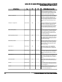
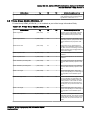
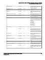
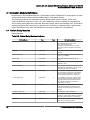
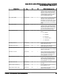
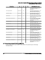
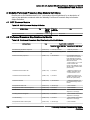
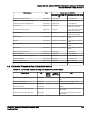
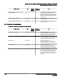
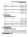
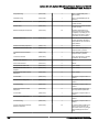
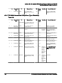
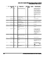
Following are the status codes that are more specifically processed when receiving messages
from a Storage SCP equipment.
Service Status
Refused
Error
38
Status Codes
Further Meaning
Application Behavior When receiv‐
ing Status Codes
Related Fields Processed if re‐
ceived
A7xx
Out of resources
"Send" operation failed. Root
(0000,0902)
cause indicated in error log. Will
continue to attempt any remaining
send operations.
0122
SOP Class not Sup‐
ported
"Send" operation failed. Root
(0000,0902)
cause indicated in error log. Will
continue to attempt any remaining
send operations.
Cxxx
Cannot Understand
"Send" operation failed. Root
(0000,0901) (0000,0902)
cause indicated in error log. Will
continue to attempt any remaining
send operations.
3 AE Specifications
Optima IGS 320, Optima IGS 330 Conformance Statement of DICOM
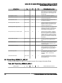
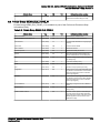
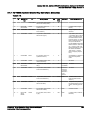
Direction 5537565-1-8EN, Revision 1
Service Status
Warning
Success
Status Codes
Further Meaning
Application Behavior When receiv‐
ing Status Codes
Related Fields Processed if re‐
ceived
A9xx
Data Set does not
match SOP Class
"Send" operation failed. Root
(0000,0901) (0000,0902)
cause indicated in error log. Will
continue to attempt any remaining
send operations.
B000
Coercion of Data Ele‐ “Send” operation successful
ments
None
B007
Data Set does not
match SOP Class
“Send” operation successful
None
B006
Elements Discarded
“Send” operation successful
None
0000
Success
“Send” operation successful
None
3.3.2 Real–World Activity Verification Acknowledge
3.3.2.1 Associated Real–World Activity
The operator must select a destination in the User Interface and press the “Verification” button.
These operations will cause:
•
the Optima DICOM Application Entity to initiate a DICOM association
•
the Optima DICOM Application Entity to emit a C–ECHO command to check if the remote
AE is available
3.3.2.2 Proposed Presentation Context Table
Presentation Context Table – Proposed
Abstract Syntax
Name
Verification
UID
1.2.840.10008.1.1
Transfer Syntax
Name List
Implicit VR Little Endian
UID List
1.2.840.10008.1.2
Role
Extended
Negotiation
SCU
None
SOP Specific DICOM Conformance Statement for Verification SOP Class:
The Optima DICOM AE provides standard conformance to the DICOM Verification SOP class.
NOTE:
The default timeout to receive the C-ECHO response is 30 secs and is not
configurable.
3.3.3 Real-World Activity Get Worklist
3.3.3.1 Associated Real-World Activity
The worklist transfer can be initiated either automatically when the DL application starts, or
manually by either clicking the “Refresh” button in the Patient Browser interface or the “Refresh
now” button in the “Define Worklist Settings” screen.
These operation will cause:
•
the Optima Application Entity to initiate a DICOM association
•
the Optima DL application to build the C–FIND request
•
the Optima Application Entity to emit the C–FIND request
•
the Optima Application Entity to receive the C–FIND Reponse(s)
Chapter 3 Network Conformance Statement
39
Optima IGS 320, Optima IGS 330 Conformance Statement of DICOM
Direction 5537565-1-8EN, Revision 1
•
the Optima Application Entity to close the association
•
the possibility for the user to add a new item to the local database
While the query is in progress, it is possible to cancel it by pressing a button on the patient
browser. This will cause a C–FIND cancel to be sent.
3.3.3.2 Proposed Presentation Context Table
Presentation Context Table – Proposed
Abstract Syntax
Name
Modality Work‐
list Information
Model – FIND
Transfer Syntax
UID
1.2.840.10008.5.1.4.31
Name List
UID List
Implicit VR Little Endian
1.2.840.10008.1.2
Role
Extended
Negotiation
SCU
None
SOP Specific DICOM Conformance Statement for the Modality Worklist Information Model –
FIND SOP Class:
Following are the status codes that are more specifically processed when receiving messages
from a Modality Worklist SCP equipment :
Service Status
Refused
Further Meaning
Application Behavior When re‐
ceiving Status Codes
Related Fields Processed
if received
A700
Out of resources
A message is displayed; with text (0000,0902)
“Last query failed” (more detailed
information is logged in the error
log).
0122
SOP Class not Supported
A message is displayed; with text (0000,0902)
“Last query failed” (more detailed
information is logged in the error
log).
A900
Identifier does not match SOP
class
Class A message is displayed;
(0000,0901) (0000,0902)
with text “Last query failed” (more
detailed information is logged in
the error log).
Cxxx
Unable to process
A message is displayed; with text (0000,0901) (0000,0902)
“Last query failed” (more detailed
information is logged in the error
log).
Cancel
FE00
Matching terminated due to can‐ A message is displayed; with text None
cel
“Canceled”.
Success
0000
Matching is complete – No final
identifier is supplied
Pending
FF00
Matches are continuing – Cur‐
None
rent Match is supplied and any
Optional Keys were supported in
the same manner as Required
Keys.
None
FF01
Matches are continuing – Warn‐
ing that one or more Optional
Keys were not supported for ex‐
istence for this Identifier
None
Failed
40
Status Codes
Worklist matches are displayed.
None
None
3 AE Specifications
Optima IGS 320, Optima IGS 330 Conformance Statement of DICOM
Direction 5537565-1-8EN, Revision 1
Service Status
*
Status Codes
*
NOTE:
Further Meaning
Any other status code
Application Behavior When re‐
ceiving Status Codes
Related Fields Processed
if received
A message is displayed; with text None
“Last query failed” (more detailed
information is logged in the error
log).
The default timeout to receive the C-FIND response is 30 secs and is not
configurable.
3.3.4 Real-World Activity Request Storage Commitment
3.3.4.1 Associated Real–World Activity
The operator may configure the image storage destination host and/or Dose SR storage
destination host to have an associated Storage Commitment SCP AE (this can be the same AE
as the Storage SCP). If there is an associated Storage Commitment SCP specified, after each
successful image transfer and/or Dose transfer the system will automatically:
1. Wait for a configurable delay time (this allows re-routing of images / Dose SR’s from Storage
SCP to the Storage Commitment SCP, if needed),
2. Initiate a DICOM association to the Storage Commitment SCP to send the storage
commitment request.
3.3.4.2 Proposed Presentation Context Table
Presentation Context Table – Proposed
Abstract Syntax
Name
UID
Transfer Syntax
Name List
UID List
Role
Extended
Negotiation
Storage Com‐
mitment Push
Model
1.2.840.10008.20.1
Implicit VR Little Endian
1.2.840.10008.1.2
SCU
None
Storage Com‐
mitment Push
Model
1.2.840.10008.20.1
Explicit VR Little Endian
1.2.840.10008.1.2.1
SCU
None
SOP Specific DICOM Conformance Statement for the Storage Commitment Push Model SOP
Class SCU:
The Storage Commitment will be requested for all SOP Instances for which the image transfer
and/or Dose SR transfer was successful. Each request may include one or more SOP
Instances, depending on the number of images that were transferred. For Dose SR’s, each
request includes only one SOP Instance.
The AE uses DICOM network storage services to transfer SOP Instances which are to be
committed.
The AE may request Storage Commitment for Instances of any of the Composite SOP Classes
it supports as an SCU (see Chapter 4, X-Ray Angiography (XA) Information Object
Implementation, Chapter 5, SC Information Object Implementation and see Chapter 9, X-Ray
Radiation Dose Structured Report Information Object ).
The Storage Commitment will be requested for all SOP Instances for which the image transfer
and/or Dose SR was successful.
Chapter 3 Network Conformance Statement
41
Optima IGS 320, Optima IGS 330 Conformance Statement of DICOM
Direction 5537565-1-8EN, Revision 1
The time-interval to attempt the Storage Commitment requests after the successful image
transfer and/or Dose SR is configurable. The default value is 0 seconds (i.e., immediately after
the image / Dose SR transfer).
Each Storage Commitment request (N-ACTION) may include one or more SOP Instances,
depending on the numberof images that were transferred.
For Dose SR’s, each request includes only one SOP Instance.
AE do not support the optional Storage Media File–Set ID and UID Attributes in the Storage
Commitment N–ACTION for transfer of SOP Instances by media for Storage Commitment.
The Storage Commitment Information Object is described in Storage commitment push model
information object definition (seeChapter 7, Storage commitment push model information object
definition).
The AE will generate a new transaction UID at each new Storage commitment request (N–
ACTION).
After sending the N-ACTION request to the storage commitment provider(s) and if the storage
commitment provider(s) sends a busy signal [resource limitation] as a N-ACTION response,
Optima AE can automatically retry sending the N-ACTION request to the storage commitment
provider(s). The Maximum Number of Retries and the Delay between the retries is configurable.
By default, the Maximum number of retries = 3 and Delay between auto-retries = 30 secs.
If the N-ACTION response conveys failure status, the association is closed by the AE.
Following are the status codes that are more specifically processed when receiving N-ACTION
responses from a Storage Commitment SCP:
N-ACTION response Status Codes
Service Status
Status Codes
Further Meaning
Application Behavior When Re‐
ceiving Status Codes
Related Fields Processed
if Received
Success
0000H
successful request
Waiting for storage commitment
response
None
Failed
0213H
Resource limitation
Automatic retry of storage com‐
None
mitment request for a configura‐
ble number of times with a config‐
urable delay between retries
Failed
Other than
above
Failure reason other than re‐
source limitation
Display error status in network
queue
None
After receiving the successful N-ACTION response, AE will keep the association open for a
configurable delay (default is 60 seconds). During this delay, AE will accept N-EVENT-REPORT
requests sent by the remote SCP for the SOP instances referenced in the current N-ACTION
request or any N-ACTION request(s) sent previously. The association is closed when this
timeout expires and there is no active transaction performed by the system linked to this
association.
If an N-EVENT-REPORT request is received on this association, the AE will process it, and
send an N-EVENT-REPORT response on the same association. The association will not be
closed by the AE even if the N-EVENT-REPORT conveys failure.
Upon receiving a Storage Commitment N–EVENT–REPORT (Storage Commitment Result), the
Optima will mark all SOP Instances for which a success status is indicated. Only Patients,
42
3 AE Specifications
Optima IGS 320, Optima IGS 330 Conformance Statement of DICOM
Direction 5537565-1-8EN, Revision 1
Studies or Instances marked “COMPLETED” may be deleted by user action without double
confirmation.
If the Storage Commitment Result indicates any failure status, an error message will be
displayed to the user, and the error, including the Failure Reason (0008,1197) attribute values,
will be written to the error log. Any retry will be manually reinitiated.
On retry the AE will transfer again the instances, and then initiate a new Storage Commitment
Request for them. The AE will process each Failure Reason Code as described below:
Failure
Reason
Meaning
Application Behavior When Receiving Reason Code
0110H
Processing failure
Display error in network queue
0112H
No such object instance
Display error in network queue
0213H
Resource limitation
Display error in network queue
0122H
Referenced SOP Class not supported
Display error in network queue
0119H
Class/Instance conflict
Display error in network queue
0131H
Duplicate transaction UID
Display error in network queue
*
Any other status code
Display error in network queue
In case of the timeout, AE can receive N–EVENT–REPORT on the Association initiated by the
Storage Commitment SCP Application Entity.
It will be processed as described for Association initiated by the Storage Commitment SCP (see
Section 3.4.3).
The AE will return the standard status codes in N–EVENT–REPORT–RSP message as
specified below:
Service Status
Failure
Success
Status Codes
Further Meaning
Further Meaning
0119
Class-instance conflict
The specified SOP Instance is not a member of
the specified SOP class.
0112
No such SOP Instance
The SOP Instance UID specified implied a viola‐
tion of the UID construction rules.
0110
Processing failure
A general failure in processing the operation
was encountered.
0000
Successful notification.
3.3.5 Real-world Activity Send MPPS
3.3.5.1 Associated Real-world Activity
This implementation provides for simple transfer of procedure and image information using the
DICOM Modality Performed Procedure Step SOP Class as a Service Class User (SCU).
The Performed Procedure Step N-CREATE message is sent automatically when the user starts
the exam and after a worklist entry has been selected or patient data have been entered on the
patient data entry screen. There is no operator intervention required.
The Performed Procedure Step N-SET message is sent automatically after the exam has been
ended. There is no operator intervention required. If the operator successfully ended the exam,
a COMPLETED status is sent. If the operator aborted the exam, a DISCONTINUED status is
Chapter 3 Network Conformance Statement
43
Optima IGS 320, Optima IGS 330 Conformance Statement of DICOM
Direction 5537565-1-8EN, Revision 1
sent, and the user can select the discontinuation reason from a predefined list or add custom
reason codes.
3.3.5.2 Proposed Presentation context table
Presentation Context Table – Proposed
Abstract Syntax
Name
UID
Transfer Syntax
Name List
UID List
Role
Extended
Negotiation
Modality Per‐
formed Proce‐
dure Step
1.2.840.10008.3.1.2.3.3
Implicit VR Little Endian
1.2.840.10008.1.2
SCU
None
Modality Per‐
formed Proce‐
dure Step
1.2.840.10008.3.1.2.3.3
Explicit VR Little Endian
1.2.840.10008.1.2.1
SCU
None
SOP Specific DICOM Conformance Statement for Modality Performed Procedure Step SOP
Class:
•
Optima includes Attributes in the Modality Performed Procedure Step N-CREATE as
described in Chapter 8, Modality Performed Procedure Step Implementation.
•
Optima includes Attributes in the Modality Performed Procedure Step N-SET as described in
Chapter 8, Modality Performed Procedure Step Implementation.
•
Optima sends N-SET after the exam is ended. The N-SET will include all acquired images
SOP Instance UIDs and the status of COMPLETED or DISCONTINUED. It will not include
reference of the Secondary Capture Image SOP Instances.
•
For this SOP class, all status codes with status Refused or Error are treated as failures and
terminate the association and operation. All status codes with status Warning or Success
are treated as successes.
•
If either N-CREATE or N-SET fails, the MPPS transaction is considered to be failed.
•
If N-CREATE fails, the corresponding N-SET will not be sent to the SCP. Re-sending failed
MPPS, will re-send both N-CREATE and N-SET to the SCP.
•
If N-CREATE succeeds and N-SET fails, Re-sending failed MPPS, will only re-send the
failed N-SET to the SCP.
NOTE:
The default timeout to receive the N-CREATE or N-SET response is 10 secs and is
not configurable.
3.4 Association Acceptance Policy
3.4.1 Introduction
The Optima DICOM AE places no limitation on who may connect to it.
Any remote AE can open an association to the Optima DICOM AE for the purpose of application
level communication verification.
44
3 AE Specifications
Optima IGS 320, Optima IGS 330 Conformance Statement of DICOM
Direction 5537565-1-8EN, Revision 1
3.4.2 Real-World Activity Verification Acknowledge
3.4.2.1 Associated Real-World Activity
The Optima DICOM AE is always listening to associations. No operator action is required to
respond to a Verification request from any DICOM node.
3.4.2.2 Accepted Presentation Context Table
Presentation Context Table - Proposed
Abstract Syntax
Name
Transfer Syntax
UID
Verification SOP 1.2.840.10008.1.1
Class
Name List
UID List
Implicit VR Little Endian
Explicit VR Little Endian
Explicit VR Big Endian
1.2.840.10008.1.2
1.2.840.10008.1.2.1
1.2.840.10008.1.2.1.2
Role
Extended
Negotiation
SCP
None
SOP Specific Conformance Statement for Verification SOP Class:
Optima DICOM Application provides standard conformance to the DICOM Verification Service
Class.
NOTE:
Optima AE will time-out 60 secs after Association Acknowledgment is sent and no
Verification request is received. This time-out is not configurable.
3.4.3 Real–World Activity Request Storage Commitment
3.4.3.1 Associated Real–World Activity
The AE will accept a configurable number of DICOM associations to receive the storage
commitment responses. The number of accepted associations can be configured from 1 to 5.
3.4.3.2 Accepted Presentation Context Table
Presentation Context Table – Proposed
Abstract Syntax
Name
UID
Transfer Syntax
Name List
UID List
Role
Extended
Negotiation
Storage Com‐
mitment Push
Model
1.2.840.10008.1.20.1
Implicit VR Little Endian
1.2.840.10008.1.2
SCU
Role Selec‐
tion Nego‐
tiation
Storage Com‐
mitment Push
Model
1.2.840.10008.1.20.1
Explicit VR Little Endian
1.2.840.10008.1.2.1
SCU
Role Selec‐
tion Nego‐
tiation
Storage Com‐
mitment Push
Model
1.2.840.10008.1.20.1
Implicit VR Big Endian
1.2.840.10008.1.2.2
SCU
Role Selec‐
tion Nego‐
tiation
SOP Specific DICOM Conformance Statement for the Storage Commitment Push Model SOP
Class SCU:
The Optima accept the SCU role (which must be proposed via SCP/SCU Role Selection
Negotiation) within a Presentation Context for the Storage Commitment Push Model SOP Class.
Upon receiving a Storage Commitment N–EVENT–REPORT (Storage Commitment Result), the
Optima will mark all SOP Instances for which a success status is indicated in the user interface
as successfully storage committed. When all Instances associated with a Study or a Patient are
Archived, the Study or Patient will also be shown on the user interface with status
Chapter 3 Network Conformance Statement
45
Optima IGS 320, Optima IGS 330 Conformance Statement of DICOM
Direction 5537565-1-8EN, Revision 1
“COMPLETED”. Only Patients, Studies or Instances marked “COMPLETED” may be deleted by
user action without double confirmation.
If the Storage Commitment Result indicates any failure status, an error message will be
displayed to the user, and the error, including the Failure Reason (0008,1197) attribute values,
will be written to the error log. Any retry will be manually reinitiated. On retry the AE will transfer
again the instances, and then initiate a new Storage Commitment Request for them.
The list of specific Failure Reason Codes that this AE will be able to process is described below.
Failure
Reason
Meaning
Application Behavior When Receiving Reason Code
0110H
Processing failure
Display error in network queue
0112H
No such object instance
Display error in network queue
0213H
Resource limitation
Display error in network queue
0122H
Referenced SOP Class not supported
Display error in network queue
0119H
Class/Instance conflict
Display error in network queue
0131H
Duplicate transaction UID
Display error in network queue
*
Any other status code
Display error in network queue
The AE will return the standard status codes in N–EVENT–REPORT–RSP message as
specified below.
Service Status
Failure
Success
46
Status Codes
Further Meaning
Further Meaning
0119
Class-instance conflict
The specified SOP Instance is not a member of
the specified SOP class.
0112
No such SOP Instance
The SOP Instance UID specified implied a viola‐
tion of the UID construction rules.
0110
Processing failure
A general failure in processing the operation
was encountered.
0000
Successful notification.
3 AE Specifications
Optima IGS 320, Optima IGS 330 Conformance Statement of DICOM
Direction 5537565-1-8EN, Revision 1
4 Communication Profiles
4.1 Supported Communication Stacks (PS 3.8)
DICOM Upper Layer (PS 3.8) is supported using TCP/IP.
4.2 OSI Stack
OSI stack not supported
4.3 TCP/IP Stack
The TCP/IP stack is inherited from a Windows Operating System.
4.3.1 API
Not applicable to this product.
4.3.2 Physical Media Support
DICOM is indifferent to the Physical medium over which TCP/IP executes (e.g. Ethernet
V2.0,IEEE 802.3, ATM, FDDI)
NOTE:
For more information about the Physical Media available on OPTIMA System, please
refer to the Product Data Sheet.
4.4 Additional Protocol Support
This product does not support DHCP.
4.5 IPv4 and IPv6 Support
This product supports only IPv4.
Chapter 3 Network Conformance Statement
47
Optima IGS 320, Optima IGS 330 Conformance Statement of DICOM
Direction 5537565-1-8EN, Revision 1
5 Extensions / Specializations / Privatizations
5.1 Standard Extended SOP Classes
The product provides Standard Extended Conformance to all supported SOP Classes, through
the inclusion of additional Type 3 Standard Elements and Private Data Elements. The
extensions are defined in Sections :
48
•
Chapter 4, Chapter 4 X-Ray Angiography (XA) Information Object Implementation
•
Chapter 5, Chapter 5 SC Information Object Implementation
5 Extensions / Specializations / Privatizations
Optima IGS 320, Optima IGS 330 Conformance Statement of DICOM
Direction 5537565-1-8EN, Revision 1
6 Configuration
GEMS Field Service Engineers configure the OPTIMA System. The DICOM configuration items
below are configurable or re–configurable by a Field Service Engineer.
6.1 AE Title/Presentation Address Mapping
The OPTIMA System DICOM SERVER AE allows for the configuration of the mapping of
remote AE titles to IP addresses and ports. The IP address of a remote AE may be in a different
sub net (using routing). GEMS Field Service Engineers perform this configuration.
6.2 Configurable Parameters
The following fields are configurable for this AE (local):
•
Local AE Title
•
Local IP Address
•
Local IP Netmask
NOTE:
The local listening port number is not configurable for this product, and is equal to
4002.
The following field is configurable for the DICOM AE used as store SCP:
•
Push Timeout - After the transfer of images, Optima waits for this maximum time period to
receive the response from the storage provider(s).
The following fields are configurable for the DICOM AE used as storage commitment SCP:
•
Delay after Push - After the images have been successfully exported to the receiving
station, this parameter determines the amount of time Optima waits to attempt the Storage
Commitment requests to the Storage Commitment provider(s).
•
Request timeout - Amount of time the association is held open after the Storage
Commitment request is sent. If the timeout is over, Optima will automatically release the
association without receiving acknowledgement from the storage commitment provider(s).
The default request timeout value is 60 sec.
•
Maximum number of concurrent associations - Maximum number of simultaneous
connections that Optima can accept from the storage commitment provider(s) to receive the
storage commitment responses.
•
Maximum number of automatic retry - After sending the Storage commitment request to the
storage commitment provider(s) and if the storage commitment provider(s) sends a busy
signal [resource limitation] as a Storage commitment response, this parameter determines
the maximum number of times, Optima automatically retries sending the storage
commitment request to the storage commitment provider(s).
•
Delay between automatic retries - After sending the Storage commitment request to the
storage commitment provider(s) and if the storage commitment provider(s) sends a busy
signal as a Storage commitment response, this parameter determines the delay between
the automatic retries of Optima.
NOTE:
A GE Field Engineer must perform all the above configurations.
Chapter 3 Network Conformance Statement
49
Optima IGS 320, Optima IGS 330 Conformance Statement of DICOM
Direction 5537565-1-8EN, Revision 1
The following fields are configurable for every remote DICOM AE used as Image storage SCP:
•
Remote AE Title
•
Remote IP Address
•
Listening TCP/IP Port Number
•
Array size of the pixel data to be transferred (512x512, or any size up to 1024x1024).
•
General Settings
○ 3D Reconstruct Host
○ Auto Push Default
■ Auto Push - If this parameter is set, at the end of every acquisition, Optima
automatically pushes the images to the storage provider(s).
The following fields are configurable for every remote DICOM AE used as Image storage
commitment SCP:
•
Archive Station Option
•
Remote Storage Commitment SCP AE Title
•
Remote Storage Commitment SCP IP Address
•
Remote Storage Commitment SCP Listening TCP/IP Port Number.
The following fields are configurable for every remote DICOM AE used as Dose SR storage
SCP:
•
Remote AE Title
•
Remote IP Address
•
Listening TCP/IP Port Number
The following fields are configurable for every remote DICOM AE used as Dose SR storage
commitment SCP:
•
Archive Station Option
•
Remote Storage Commitment SCP AE Title
•
Remote Storage Commitment SCP IP Address
•
Remote Storage Commitment SCP Listening TCP/IP Port Number
The following fields are configurable for the DICOM AE used as worklist SCP:
50
•
Remote AE Title
•
Remote IP Address
6 Configuration
Optima IGS 320, Optima IGS 330 Conformance Statement of DICOM
Direction 5537565-1-8EN, Revision 1
•
Listening TCP/IP Port Number
•
General Settings
- Automatic Retrieve of Worklist at boot option
•
The default request timeout value is 60sec
The following fields are configurable for the DICOM AE used as MPPS SCP:
•
Remote AE Title
•
Remote IP Address
•
Listening TCP/IP Port Number
Chapter 3 Network Conformance Statement
51
Optima IGS 320, Optima IGS 330 Conformance Statement of DICOM
Direction 5537565-1-8EN, Revision 1
7 Support of Extended Character Sets
The Optima system generates only a single-byte character set ISO_IR 100 (Latin alphabet
Number 1 supplementary set).
The product user interface will allow the user to enter characters from the console keyboard that
are within ISO_IR 100 (Latin alphabet Number 1 supplementary set).
As a Modality Worklist SCU, the product will accept the worklist responses only if it satisfies the
following:
•
Attribute Specific Character Set (0008,0005) is not present
•
Attribute Specific Character Set (0008,0005) has only a single value and the value is either
ISO_IR 100 (or) ISO_IR 6
•
Attribute Specific Character Set (0008,0005) has more than one value and the first value is
either not present (or) ISO_IR 100 (or) ISO_IR 6
The product will reject the worklist responses that do not satisfy the conditions listed above.
Text attributes of the Scheduled Procedure Step Identifier, including Patient and Physician
names, that include extended characters will be displayed considering only the first character
set and hence only the first component group will be used. All other component groups of
Person names will be ignored by the system.
52
7 Support of Extended Character Sets
Optima IGS 320, Optima IGS 330 Conformance Statement of DICOM
Direction 5537565-1-8EN, Revision 1
Chapter 4 X-Ray Angiography (XA) Information Object
Implementation
1 Introduction
This section specifies the use of the DICOM X-Ray Angiographic Image IOD to represent the
information included in X-Ray Angiographic Images produced by this implementation.
Corresponding attributes are conveyed using the module construct.
Chapter 4 X-Ray Angiography (XA) Information Object
Implementation
53
Optima IGS 320, Optima IGS 330 Conformance Statement of DICOM
Direction 5537565-1-8EN, Revision 1
2 Optima Mapping of DICOM Entities
The Optima maps DICOM Information Entities to local Information Entities in the product’s
database and user interface.
Table 4-1: Mapping of DICOM Entities to Optima Entities
54
DICOM IE
Optima Entity
Patient
Patient
Study
Exam
Series
Exam
Image
Sequence
2 Optima Mapping of DICOM Entities
Optima IGS 320, Optima IGS 330 Conformance Statement of DICOM
Direction 5537565-1-8EN, Revision 1
3 IOD Module Table
The X-Ray Angiographic Image Information Object Definition comprises the modules of the
following table, plus Standard Extended and Private attributes. Standard Extended and Private
attributes are described in Section Standard Extended and Private Data Attributes.
Table 4-2: X-Ray Angiographic Image IOD Modules
Entity Name
Usage
Reference
Used
Section 4.1, Patient Entity Mod‐
ules
Not Used
N/A
General Study
Used
Section 4.2.1, General Study
Module
Patient Study
Used
Section 4.2.2, Patient Study Mod‐
ule
Not Used
N/A
Used
Section 4.3, Series Entity Mod‐
ules
Clinical Trial Series
Not Used
N/A
Frame of Reference
Synchronization
Not Used
N/A
Equipment
General Equipment
Used
Section 4.4, Equipment Entity
Modules
Frame of Reference
Synchronization
Not Used
N/A
Image
General Image
Used
Section 4.5.1, General Image
Module
Image Pixel
Used
Section 4.5.2, Image Pixel Mod‐
ule
Used
Required if contrast media
was used in this image.
Section 4.5.3, Contrast/Bolus
Module
Cine
Used
Required if pixel data is MultiFrame Cine data.
Section 4.5.4, Cine Module
Multi-Frame
Used
Section 4.5.5, Multi–Frame Mod‐
Required if pixel data is Multiule
Frame Cine data.
Patient
Module Name
Patient
Clinical Trial Subject
Study
Clinical Trial Study
Series
General Series
Contrast/Bolus
Frame Pointers
Used
Section 4.5.6, Frame Pointers
Module
Used
Required if the Image may be
subtracted.
Section 4.5.7, Mask Module
Used
Section 4.5.8, Display Shutter
Module
Device
Not Used
N/A
Intervention
Not Used
N/A
Specimen
Not Used
N/A
Used
Section 4.5.9, X-Ray Image Mod‐
ule
Mask
Display Shutter
X-Ray Image
Chapter 4 X-Ray Angiography (XA) Information Object
Implementation
55
Optima IGS 320, Optima IGS 330 Conformance Statement of DICOM
Direction 5537565-1-8EN, Revision 1
Entity Name
56
Module Name
Usage
Reference
X-Ray Acquisition
Used
Section 4.5.10, X-Ray Acquisition
Module
X-Ray Collimator
Used
Section 4.5.11, X–Ray Collimator
Module
X-Ray Table
Used
Required if image is created
with table motion. May be
present otherwise.
Section 4.5.12, X–Ray Table
Module
XA Positioner
Used
Section 4.5.13, XA Positioner
Module
DX Detector
Used
Section 4.5.14, DX Detector Mod‐
ule
Overlay Plane
Not Used
N/A
Multi-Frame Overlay
Not Used
N/A
Modality LUT
Not Used
N/A
VOI LUT
Used
Section 4.5.15, VOI LUT module
SOP Common
Used
Section 4.5.16, SOP Common
Module
3 IOD Module Table
Optima IGS 320, Optima IGS 330 Conformance Statement of DICOM
Direction 5537565-1-8EN, Revision 1
4 Information Module Definitions
Please refer to DICOM Part 3 (Information Object Definitions) for a description of each of the
entities, modules, and attributes contained within the X-Ray Angiographic Information Object.
The following modules are included to convey Enumerated Values, Defined Terms, and
Optional Attributes supported. Type 1 & Type 2 Attributes are also included for completeness
and to define what values they may take. It should be noted that they are the same ones as
defined in the DICOM Standard Part 3 (Information Object Definitions). Also note that Attributes
not present in tables are not supported.
4.1 Patient Entity Modules
Patient Module
Table 4-3: Patient Module Attributes
Attribute Name
Tag
Type
Patient’s Name
(0010,0010)
2
From user interface or worklist. When from user interface,
value contains only last_name(restricted to 32
chars)^first_name(restricted to 31 chars). When from work‐
list, equals first component group.
Patient ID
(0010,0020)
2
From worklist or user interface. Restricted to 64 chars.
Patient’s Birth Date
(0010,0030)
2
From user interface or worklist. Restricted to 8 chars.
YYYYMMDD.
Patient’s Sex
(0010,0040)
2
From user interface or worklist. ”M”, ”F” or ”O”.
Other Patient ID
(0010,1000)
3
Other patient identifier or code. From Worklist or User Inter‐
face.
Issuer of Patient ID
(0010,0021)
3
From Worklist. Identifier of the Assigning Authority (system,
organization, agency, or department) that issued the Patient
ID.
Issuer of Patient ID Qualifi‐
ers Sequence
(0010,0024)
3
From Worklist. Attributes specifying or qualifying the identity
of the issuer of the Patient ID, or scoping the Patient ID. On‐
ly a single Item shall be permitted in this sequence.
> Universal Entity ID
(0040,0032)
3
From Worklist. Universal or unique identifier for the Patient
ID Assigning Authority. The authority identified by this attrib‐
ute shall be the same as that of Issuer of Patient ID
(0010,0021), if present.
> Universal Entity ID Type
(0040,0033)
1C
From Worklist. Standard defining the format of the Universal
Entity ID (0040,0032). Required if Universal Entity ID
(0040,0032) is present.
> Identifier Type Code
(0040,0035)
3
From Worklist. Type of Patient ID.
Other Patient IDs Sequence
(0010,1002)
3
From Worklist. A sequence of identification numbers or co‐
des used to identify the patient. If present, shall contain one
or more items.
> Patient ID
(0010,0020)
1
From Worklist. An identification number or code used to
identify the patient.
> Issuer of Patient ID
(0010,0021)
1
From Worklist. Identifier of the Assigning Authority (system,
organization, agency, or department) that issued the Patient
ID.
Chapter 4 X-Ray Angiography (XA) Information Object
Implementation
Attribute Description
57
Optima IGS 320, Optima IGS 330 Conformance Statement of DICOM
Direction 5537565-1-8EN, Revision 1
Attribute Name
>Type of Patient ID
Tag
Type
(0010,0022)
1
Attribute Description
From Worklist. The type of identifier in this item. Defined
Terms:
TEXT
RFID
BARCODE
4.2 Study Entity Modules
4.2.1 General Study Module
Table 4-4: General Study Module Attributes
Attribute Name
Tag
Type
Attribute Description
Study Instance UID
(0020,000D)
1
From Worklist. Otherwise, Internally generated as follows:
"registered prefix for GEMS" + ".2. Registered prefix within
GEMS" + ".a.b.c" encoded mac address of the DL host
+".x.y.z" unique id protected against reinstallation and re-en‐
trance.
Study Date
(0008,0020)
2
YYYYMMDD, restricted to 8 characters.
Study Time
(0008,0030)
2
HHMMSS.XXX, restricted to 10 characters.
Referring Physician’s Name
(0008,0090)
2
From User Interface or worklist, restricted to 64 characters.
Study ID
(0020,0010)
2
From User Interface or Worklist, restricted to 16 characters.
Accession Number
(0008,0050)
2
From User Interface or Worklist, restricted to 16 characters.
Study Description
(0008,1030)
3
Generated description from the worklist entries.If no value
found,value is taken from user interface.
Name of Physician(s) Read‐
ing Study
(0008,1060)
3
From User Interface, restricted to 64 characters. Value con‐
tains only one component. (May not be sent).
Reference Study Sequence
(0008,1110)
3
From Worklist. The sequence may have zero or more Items.
>Reference SOP Class UID
(0008,1150)
1
From Worklist. Required if a sequence item is present.
>Reference SOP instance
UID
(0008,1155)
1
From Worklist. Required if a sequence item is present.
Performed Procedure Code
Sequence
(0008,1032)
3
A Sequence that conveys the type of procedure performed.
Present if MPPS option is enabled. (May not be sent)
>Code Value
(0008,0100)
1C
Required if a sequence item is present.
>Code schema designator
(0008,0102)
1C
Required if a sequence item is present.
>Code meaning
(0008,0104)
1C
Required if a sequence item is present.
4.2.2 Patient Study Module
Table 4-5: Patient Study Module Attributes
Attribute Name
58
Tag
Type
Attribute Description
Patient’s Age
(0010,1010)
3
Either from User Interface or Calculated from Patient’s Birth
Date (0010,0030). Three digits followed by one letter: In
Years (Y), Months (M), Weeks (W) or Days (D). (May not be
sent).
Patient’s Size
(0010,1020)
3
From User Interface or worklist, restricted to 16 characters.
(May not be sent).
4 Information Module Definitions
Optima IGS 320, Optima IGS 330 Conformance Statement of DICOM
Direction 5537565-1-8EN, Revision 1
Attribute Name
Tag
Type
Attribute Description
Patient’s Weight
(0010,1030)
3
From User Interface or worklist, restricted to 16 characters.
(May not be sent).
Admission ID
(0038,0010)
3
From Worklist, Identification number of the visit as assigned
by the healthcare provider. (May not be sent)
4.3 Series Entity Modules
General Series Module
Table 4-6: General Series Module Attributes
Attribute Name
Tag
Type
Modality
(0008,0060)
1
“XA”
Series Instance UID
(0020,000E)
1
Restricted to 64 characters, internally generated as fol‐
lows: ”registered prefix for GEMS” + ”.2. Registered prefix with‐
in GEMS” + ”.a.b.c” encoded mac address of the DL host
+”.x.y.z” unique id protected against reinstallation and reen‐
trance.
Series Number
(0020,0011)
2
Internally generated, starting at 1.
Series Date
(0008,0021)
3
YYYYMMDD, restricted to 8 characters.
Series Time
(0008,0031)
3
HHMMSS.XXX, restricted to 10 characters.
Performing Physicians’
Name
(0008,1050)
3
From User Interface, restricted to 64 characters.
Protocol Name
(0018,1030)
3
From User Interface, user defined description of the acquisition
protocol.
Series Description
(0008,103E)
3
Internally generated Series Description using Study/RP/SPS in‐
formation (May not be sent).
Operators’ Name
(0008,1070)
3
From User Interface, restricted to 64 characters. (May not be
sent).
Referenced Performed
Procedure Step Sequence
(0008,1111)
3
Uniquely identifies the Modality Performed Procedure Step
SOP Instance. Present only if MPPS Option is enabled. (May
not be sent).
>Reference SOP Class
UID
(0008,1150)
1C
Uniquely identifies the MPPS SOP Class. Required if a se‐
quence item is present.
>Reference SOP instance
UID
(0008,1155)
1C
Uniquely identifies the MPPS SOP Instance. Required if a se‐
quence item is present.
Chapter 4 X-Ray Angiography (XA) Information Object
Implementation
Attribute Description
59
Optima IGS 320, Optima IGS 330 Conformance Statement of DICOM
Direction 5537565-1-8EN, Revision 1
Attribute Name
Patient position
60
Tag
Type
(0018,5100)
2C
Attribute Description
Patient position descriptor relative to the equipment.
Defined terms are:
• HFP = Head First-Prone
•
HFS = Head First- Supine
•
HFDR = Head First-Decubitus Right
•
HFDL = Head First-Decubitus Left
•
FFDR = Feet First-Decubitus Right
•
FFDL = Feet First-Decubitus Left
•
FFP = Feet First-Prone
•
FFS = Feet First- Supine
Body Part Examined
(0018,0015)
3
Text description of the part of the body examined.
Request attribute se‐
quence
(0040,0275)
3
Sequence that contains attributes from the Imaging Service Re‐
quest. The sequence may have only one item.
>Request procedure id
(0040,1001)
1C
Identifier that identifies the Requested Procedure in the Imaging
Service Request. Required if Sequence Item is present.
>Requested Procedure
Description
(0032,1060)
3
Institution-generated administrative description or classification
of Requested Procedure. (May not be sent)
>Requested procedure
Code Sequence
(0032,1064)
3
A sequence that conveys the procedure Type of the requested
procedure. The Requested Procedure Code Sequence shall
contain only a single item.
>>Code Value
(0008,0100)
1C
Required if a sequence item is present.
>>Code schema designa‐
tor
(0008,0102)
1C
Required if a sequence item is present.
>>Code meaning
(0008,0104)
1C
Required if a sequence item is present.
>Scheduled Procedure
Step ID
(0040,0009)
1C
Identifier that identifies the Scheduled Procedure step.
>Scheduled Procedure
Step Description
(0040,0007)
3
Institution-generated description or classification of the Sched‐
uled Procedure Step to be performed.
>Scheduled Protocol Code
Sequence
(0040,0008)
3
Sequence describing the Scheduled Protocol following a specif‐
ic coding Scheme.
>>Code Value
(0008,0100)
1C
Required if a sequence item is present.
>>Code schema designa‐
tor
(0008,0102)
1C
Required if a sequence item is present.
>>Code meaning
(0008,0104)
1C
Required if a sequence item is present.
Performed Procedure Step
ID
(0040,0253)
3
Internally generated identifier.
Performed Procedure Step
Start Date
(0040,0244)
3
Date on which the Performed Procedure step started. Same as
Study Date.
Performed Procedure Step
Start Time
(0040, 0245)
3
Time on which the Performed Procedure Step started. Same as
Study Time.
Performed Procedure Step
Description
(0040,0254)
3
description of the Procedure Step that was performed.
4 Information Module Definitions
Optima IGS 320, Optima IGS 330 Conformance Statement of DICOM
Direction 5537565-1-8EN, Revision 1
4.4 Equipment Entity Modules
General Equipment Module
Table 4-7: General Equipment Module Attributes
Attribute Name
Tag
Type
Attribute Description
Manufacturer
(0008,0070)
2
“GE MEDICAL SYSTEMS”
Institution Name
(0008,0080)
3
From ”Service User Interface”, configured at the instal‐
lation of the system. Restricted to 64 characters.
Institution Address
(0008,0081)
3
From ”Service User Interface”, configured at the instal‐
lation of the system. Restricted to 1024 characters.
Station name
(0008,1010)
3
AE Title of the system that created the DICOM image.
Manufacturer’s Model Name
(0008,1090)
3
“DL”
Device Serial Number
(0018,1000)
3
Manufacturer's serial number of the equipment. From
internal configuration of the machine.
Software Versions
(0018,1020)
3
DL application version.
Gantry ID
(0018,1008)
3
Identifier of the gantry or positioner. Value = “LC”.
4.5 Image Entity Modules
4.5.1 General Image Module
Table 4-8: General Image Module Attributes
Attribute Name
Tag
Type
Instance Number
(0020,0013)
2
Patient Orientation
(0020,0020)
2C
Patient direction of the rows and columns of the image.
This attribute contains the values corresponding to the
first frame.
Content Date
(0008,0023)
2C
Same as acquisition date (0008,0022).
Content Time
(0008,0033)
2C
Same as acquisition time (0008,0032).
Image Type
(0008,0008)
3
See Table 4-17: Image type
Acquisition Date
(0008,0022)
3
YYYYMMDD, restricted to 8 characters, date the se‐
quence was acquired.
Acquisition Time
(0008,0032)
3
HHMMSS.XXX, restricted to 10 characters.
Image Comments
(0020,4000)
3
From User Interface, restricted to 64 characters.
Irradiation Event UID
(0008,3010)
3
Unique identification of the irradiation event(s) associ‐
ated with the acquisition of this image.
Source Image Sequence
(0008,2112)
3
A sequence which identifies the set of image SOP
Class/Instance pairs of the image which were used to
derive this image.
> Referenced SOP Class UID
(0008,1150)
1C
Uniquely identifies the referenced SOP Class.
> Referenced SOP Instance
UID
(0008,1155)
1C
Uniquely identifies the referenced SOP Instance.
> Purpose of Reference Code
Sequence
(0040,A170)
3
Chapter 4 X-Ray Angiography (XA) Information Object
Implementation
Attribute Description
Internally generated, starting at 1.
Describes the purpose for which the reference is made,
that is what role the source image or frame(s) played in
the derivation of this image.
61
Optima IGS 320, Optima IGS 330 Conformance Statement of DICOM
Direction 5537565-1-8EN, Revision 1
Attribute Name
Tag
Type
Attribute Description
>> Code Value
(0008,0100)
1
Required if sequence item is present.
>> Coding Scheme Designator
(0008,0102)
1
Required if sequence item is present.
>> Code meaning
(0008,0104)
1
Required if sequence item is present.
Derivation Description
(0008,2111)
3
Hardcoded to “STENTVESSELVIZ” for the stentvessel‐
viz post processed image.
Tag
Type
Attribute Description
Samples per Pixel
(0028,0002)
1
“1”
Photometric Interpretation
(0028,0004)
1
MONOCHROME2
Rows
(0028,0010)
1
Depends on the size of the FOV (imaged region of the
X-ray detector), and the re-sampling applied during the
DICOM conversion. Possible values are 1024, 1000,
864, 736, 608, 750, 800, 512 and 500.
Columns
(0028,0011)
1
Depends on the size of the FOV (imaged region of the
X-ray detector), and the re-sampling applied during the
DICOM conversion. Possible values are 1024, 1000,
864, 736, 608, 750, 800, 512 and 500.
Bits Allocated
(0028,0100)
1
8 or 16
Bits Stored
(0028,0101)
1
8 or 12
High Bit
(0028,0102)
1
7 or 11
Pixel Representation
(0028,0103)
1
“0”
Pixel Data
(7FE0,0010)
1
Data stream of the pixel samples.
4.5.2 Image Pixel Module
Table 4-9: Image Pixel Module Attributes
Attribute Name
4.5.3 Contrast/Bolus Module
This module is used only if contrast media was used in this image.
Table 4-10: Contrast/Bolus Module Attributes
Attribute Name
Contrast/Bolus Agent
Tag
Type
(0018,0010)
2
Attribute Description
EMPTY
4.5.4 Cine Module
This module is used only if pixel data is Multi-Frame Cine data.
Table 4-11: Cine Module Attributes
Attribute Name
Frame Time
62
Tag
Type
(0018,1063)
1C
Attribute Description
Nominal time (in msec) between frames. Required if
frame increment pointer (0028,0009) points to frame
time.
4 Information Module Definitions
Optima IGS 320, Optima IGS 330 Conformance Statement of DICOM
Direction 5537565-1-8EN, Revision 1
Attribute Name
Tag
Type
Attribute Description
Frame time vector
(0018,1065)
1C
An array which contains the real time increments (in
msec) between frames for a Multi-frame image. Re‐
quired if Frame Increment Pointer (0028,0009) points to
Frame Time Vector. If exist, the interval time values of
the intervals during acquisition (e.g. between two sec‐
tions or segments).
Start Trim
(0008,2142)
3
The frame number of the next frame after the last trial
image.
Stop Trim
(0008,2143)
3
Last frame of the multi–frame image.
Recommended Display Frame
Rate
(0008,2144)
3
Number of frames per second (truncated to integer).
Cine Rate
(0018,0040)
3
Number of frames per second (truncated to integer).
Frame Delay
(0018,1066)
0
“0”.
4.5.5 Multi–Frame Module
This module is used only if pixel data is Multi-Frame Cine data.
Table 4-12: Multi–Frame Module Attributes
Attribute Name
Tag
Type
Attribute Description
Number of Frames
(0028,0008)
1
Internally generated by acquisition system. Maximum:
460.
Frame Increment Pointer
(0028,0009)
1
“(0018,1063)”OR “(0018,1065)”
4.5.6 Frame Pointers Module
Table 4-13: Frame Pointers Module Attributes
Attribute Name
Representative Frame Number
Tag
Type
(0028,6010)
3
Attribute Description
Calculated as "start_trim + (stop_trim - start_trim)/2.
4.5.7 Mask Module
This module is used only if the image may be subtracted.
Table 4-14: Mask Module Attributes
Attribute Name
Tag
Type
Mask Substraction Sequence
(0028,6100)
1
Defines a sequence which describe mask subtraction
operations for a Multi–frame Image.
>Mask Operation
(0028,6101)
1
AVG_SUB or NONE
>Applicable Frame Range
(0028,6102)
1C
Frames of the mask operation applied during the last
review.
>Mask Frame Numbers
(0028,6110)
1C
Frames selected as Mask during the last review. Re‐
quired if Mask Operation (0028,6101) is AVG_SUB.
>Mask Subpixel Shift
(0028,6114)
3
Pixel shift applied during the last review.
Recommended Viewing Mode
(0028,1090)
2
SUB or NAT
Chapter 4 X-Ray Angiography (XA) Information Object
Implementation
Attribute Description
63
Optima IGS 320, Optima IGS 330 Conformance Statement of DICOM
Direction 5537565-1-8EN, Revision 1
4.5.8 Display Shutter Module
Table 4-15: Display Shutter Module Attributes
Attribute Name
Tag
Type
Attribute Description
Shutter Shape
(0018,1600)
1
Shutter Left Vertical Edge
(0018,1602)
1C
Internally generated by acquisition system.
Shutter Right Vertical Edge
(0018,1604)
1C
Internally generated by acquisition system.
Shutter Upper Horizontal Edge
(0018,1606)
1C
Internally generated by acquisition system.
Shutter Lower Horizontal Edge
(0018,1608)
1C
Internally generated by acquisition system.
Tag
Type
Attribute Description
Image Type
(0008,0008)
1
See Table 4-17: Image type
Pixel Intensity Relationship
(0028,1040)
1
DISP, DRM or SQRT
Scan Options
(0018,0022)
3
Parameters of scanning sequence.
Calibration Image
(0050,0004)
3
Not sent
Samples per Pixel
(0028,0002)
1
See Table 4-9
Photometric Interpretation
(0028,0004)
1
See Table 4-9
Bits Allocated
(0028,0100)
1
See Table 4-9
Bits Stored
(0028,0101)
1
See Table 4-9
High Bit
(0028,0102)
1
See Table 4-9
Pixel Representation
(0028,0103)
1
See Table 4-9
“RECTANGULAR”
4.5.9 X-Ray Image Module
Table 4-16: X-Ray Image Module Attributes
Attribute Name
Image Type
Values 1, 2, 3 have the following Enumerated Values:
Table 4-17: Image Type
Enumerated Values
Value 1
ORIGINAL identifies an Original Image
or DERIVED identifies an image whose pixel value have been derived
Value 2
PRIMARY identifies a Primary Image
Value 3
SINGLE PLANE
4.5.10 X-Ray Acquisition Module
Table 4-18: X-Ray Acquisition Module Attributes
Attribute Name
64
Tag
Type
Attribute Description
Acquisition duration
(0018,9073)
3
The time in seconds needed for the com‐
plete acquisition
KVP
(0018,0060)
2
Peak kilo voltage output of the Xray gener‐
ator used.
4 Information Module Definitions
Optima IGS 320, Optima IGS 330 Conformance Statement of DICOM
Direction 5537565-1-8EN, Revision 1
Attribute Name
Tag
Type
Attribute Description
Radiation Setting
(0018,1155)
1
X-Ray Tube Current
(0018,1151)
2C
Xray tube current in mA.
Exposure Time
(0018,1150)
2C
Duration of Xray exposure in msec.
Exposure
(0018,1152)
2C
The product of exposure time and Xray
tube current expressed in mAs. Required if
either Exposure Time (0018,1150) or Xray
tube current (0018,1151) are not present.
Grid
(0018,1166)
3
Identify the grid.Defined Terms are IN(a
grid is positioned) and NONE(no grid is
used).
Average Pulse Width
(0018,1154)
3
Average width of Xray pulse in msec.
Radiation Mode
(0018,115A)
3
Specifies Xray radiation mode (CONTINU‐
OUS, PULSED).
Image and Fluoroscopy Area
Dose product
(0018,115E)
3
XRay dose, measured in dGy*cm*cm, to
which the patient was exposed for the ac‐
quisition of this image plus any Non-digital‐
ly recorded fluoro which may have been
performed to prepare for the acquisition of
this image.
Intensifier Size
(0018,1162)
3
204.8 for 20cm detector, 307.2 for 30cm
detector and 409.6 for 40cm detector.
Focal Spot
(0018,1190)
3
Nominal focal spot size in mm used to ac‐
quire this image.
Type of Filters
(0018,1161)
3
Type of filter(s) inserted into the X-Ray
beam (e.g. wedges)
Exposure in μAs
(0018,1153)
3
The exposure expressed in μAs, for exam‐
ple calculated from Exposure Time and XRay Tube Current
Identify the general level of Xray dose ex‐
posure. Enumerated values are SC=low
dose (fluoro), GR=high dose (cine).
4.5.11 X–Ray Collimator Module
Table 4-19: X-Ray Collimator Module Attributes
Attribute Name
Tag
Type
Collimator Shape
(0018,1700)
1
Collimator Left Vertical Edge
(0018,1702)
1C
Internally generated by the acquisition sys‐
tem.
Collimator Right Vertical Edge
(0018,1704)
1C
Internally generated by the acquisition sys‐
tem.
Collimator Upper Horizontal Edge
(0018,1706)
1C
Internally generated by the acquisition sys‐
tem.
Collimator Lower Horizontal Edge
(0018,1708)
1C
Internally generated by the acquisition sys‐
tem.
Chapter 4 X-Ray Angiography (XA) Information Object
Implementation
Attribute Description
RECTANGULAR
65
Optima IGS 320, Optima IGS 330 Conformance Statement of DICOM
Direction 5537565-1-8EN, Revision 1
4.5.12 X–Ray Table Module
Table 4-20: X-Ray Table Module Attributes
Attribute Name
Tag
Type
Attribute Description
Table Motion
(0018,1134)
2
Defined terms: STATIC, DYNAMIC. DYNAM‐
IC if there is any movement in table or rela‐
tive motion of table with respect to isocenter.
NOTE: Table Motion may also be set to DY‐
NAMIC when there is only a tilt table motion.
In that specific case, Table Increments will be
set to 0.
Table Vertical Increment
(0018,1135)
2C
Incremental change in Vertical position of the
table plane relative to first frame of Multiframe
image given in mm. Table motion down is
positive. Required if Table Motion is DYNAM‐
IC. NOTE: if the table is tilted, this attribute
determines a change of the tilted plane in the
vertical direction.
Table Longitudinal Increment
(0018,1137)
2C
Incremental change in Longitudinal position
of the table (in the table plane even if the ta‐
ble is tilted) relative to first frame of Multi‐
frame image given in mm. Table motion to‐
wards CRA is positive. Required if Table Mo‐
tion is DYNAMIC. NOTE: if the table is tilted
and rotated, this attribute determines a
change of the table in the tilted plane (not in
the horizontal plane) and in the CRA-CAU di‐
rection of the isocenter system, which is fixed
and independent from the rotation angle of
the table.
Table Lateral Increment
(0018,1136)
2C
Incremental change in Lateral position of the
table (in the horizontal plane) relative to first
frame of Multiframe image given in mm. Ta‐
ble motion towards LAO is positive. Required
if Table Motion is DYNAMIC. NOTE: If the ta‐
ble is rotated, this attribute determines a
change of the table position in the LAO-RAO
direction of the isocenter system, which is
fixed and independent from the rotation angle
of the table.
Table Angle
(0018,1138)
3
Angle of the head-feet axis of the table in de‐
grees relative to the horizontal plane. Zero is
defined when the head-feet axis is in the hori‐
zontal plane. Positive values are when the
head of the table is upwards the horizontal
plane. The valid range is from -45 to +45.
Contains the maximum value of all the frames
of the multi-frame image.
Tag
Type
Attribute Description
Distance Source to Patient
(0018,1111)
3
Internally generated by the acquisition sys‐
tem.
Distance Source to Detector
(0018,1110)
3
Internally generated by the acquisition sys‐
tem.
4.5.13 XA Positioner Module
Table 4-21: XA Positioner Module Attributes
Attribute Name
66
4 Information Module Definitions
Optima IGS 320, Optima IGS 330 Conformance Statement of DICOM
Direction 5537565-1-8EN, Revision 1
Attribute Name
Tag
Type
Attribute Description
Estimated Radiographic Magnification
Factor
(0018,1114)
3
Positioner Motion
(0018,1500)
2C
Positioner Primary Angle
(0018,1510)
2
Position of the Xray Image Intensifier about
the patient from the RAO to LAO direction
where movement from RAO to vertical is
positive.
For multi-frame images, value of the first
frame.
Note: The values correspond to the motions
in Pivot, C, L-arm, Rotation, Tilt, Patient Po‐
sition.
Positioner Secondary Angle
(0018,1511)
2
Position of the Xray Image Intensifier about
the patient from the CAU to CRA direction
where movement from CAU to vertical is
positive.
For multi-frame images, value of the first
frame.
Note: The values correspond to the motions
in Pivot, C, L-arm, Rotation, Tilt, Patient Po‐
sition.
Positioner Primary Angle Increment
(0018,1520)
2C
Value of the RAO/LAO increments relative to
the first frame. Required if positioner motion
is DYNAMIC.
Positioner Secondary Angle Increment
(0018,1521)
2C
Value of the CRA/CAU increments relative to
the first frame. Required if positioner motion
is DYNAMIC.
Calculated from (0018,1110) and
(0018,1111).
DYNAMIC, if Pivot moves or C-ARM moves
or L-arm moves or Tilt varies or Table rota‐
tion or ISO movement happens. If NO motion
[in Pivot or C-arm or Tilt or Table rotation or
ISO] then it will be sent as STATIC.
4.5.14 DX Detector Module
Table 4-22: DX Detector Module Attributes
Attribute Name
Tag
Type
Detector Type
(0018,7004)
2
SCINTILLATOR
Field of View Shape
(0018,1147)
3
RECTANGLE
Field of View Dimension(s)
(0018,1149)
3
From user selection in the User Interface of the ac‐
quisition system. Possible values are "400\400" OR
"320\320" OR "300\300" OR "200\200" OR "172\172"
OR "170\170" OR "160\160" OR "150\150" OR
"147\147" OR "121\121" OR "120\120".
Field Of View Origin
(0018,7030)
1C
Depends on the size of the FOV (imaged region of the
X-ray detector).
Field Of View Rotation
(0018,7032)
1C
Clockwise rotation in degrees of Field of View, that is
the image pixels stored in Pixel Data , relative to the
physical detector.
Enumerated Values:
0, 90, 180, 270
Required if Field of View Horizontal Flip (0018,7034) is
present.
Chapter 4 X-Ray Angiography (XA) Information Object
Implementation
Attribute Description
67
Optima IGS 320, Optima IGS 330 Conformance Statement of DICOM
Direction 5537565-1-8EN, Revision 1
Attribute Name
Tag
Type
Attribute Description
Field of View Horizontal Flip
(0018,7034)
1C
Whether or not a horizontal flip has been applied to the
Field of View, that is the image pixels stored in Pixel
Data (7FE0,0010), after rotation relative to the physical
detector as described in Field of View Rotation
(0018,7032).
Enumerated Values:
NO
YES
Required if Field of View Rotation (0018,7032) is
present.
Imager Pixel Spacing
(0018,1164)
1
Around 0.2 mm for FOV 120 mm to FOV 200 mm, and
around 0.4 mm for FOV 200 mm and above.
4.5.15 VOI LUT module
Table 4-23: VOI LUT Module Attributes
Attribute Name
Tag
Type
Attribute Description
Window center
(0028,1050)
1C
Value of the window center optimized at the image
acquisition.
Window width
(0028,1051)
1C
Value of the window width optimized at the image
acquisition.
4.5.16 SOP Common Module
Table 4-24: SOP Common Module Attributes
Attribute Name
68
Tag
Type
Attribute Description
SOP Class UID
(0008,0016)
1
“1.2.840.10008.5.1.4.1.1.12.1”
SOP Instance UID
(0008,0018)
1
Restricted to 64 characters, internally generated as
follows: ”registered prefix for GEMS” + ”.2. Regis‐
tered prefix within GEMS” + ”.a.b.c” encoded mac
address of the DL host +”.x.y.z” unique id protected
against reinstallation and re-entrance.
Specific Character Set
(0008,0005)
1C
Instance Number
(0020,0013)
3
'ISO_IR 100'
Internally generated, starting at 1.
4 Information Module Definitions
Optima IGS 320, Optima IGS 330 Conformance Statement of DICOM
Direction 5537565-1-8EN, Revision 1
5 Standard Extended and Private Data Attributes
The Product supports the Standard and Private Attributes defined in the following sections in
Standard Extended X-Ray Angiographic SOP Instances as Type 3 data elements.
5.1 Standard Attributes
The Product supports the following attributes, not specified in the X-Ray Angiographic IOD, in
SOP Instances as Type 3 data elements.
Table 4-25: Standard Extended Attributes
Information Entity Name
Attribute Name
Image
Tag
Use
Curve Dimensions
(5000,0005)
"2"
Number of Points
(5000,0010)
Number of data
points in this Curve.
Type of Data
(5000,0020)
"ECG”
Data Value Representation
(5000,0103)
"0000H" [unsigned
short (US) ]
Curve Data Descriptor
(5000,0110)
"0\1"
Axis Units
(5000,0030)
"DPPS\NONE"
Coordinate Start Value
(5000,0112)
“0”
Coordinate Step Value
(5000,0114)
“250”
Curve Data
(5000,3000)
Points in the curve,
each dimension for
the first point, fol‐
lowed by dimen‐
sions for second
point, etc
5.2 Private Group DLX_SERIE_01
Private Group DLX_SERIE_01 is modeled as part of the Image Information Entity.
Table 4-26: Private Group DLX_SERIE_01
Attribute Name
Tag
VR
VM
Attribute Description and Use
adx acq mode
(0019,xx14)
IS
1
This is a “numerical code” of the acquisi‐
tion mode, and is used in AW to autostart applications. Defined codes for Opti‐
ma are:
100: Fluoro Store
2: Cardiac NoSub
32: Auto DSA
116: Bolus for Pasting (Angio Sub)
126: Chase
129: 3D Calibration
140: NoSub 3D
128: Sub 3D
ip address
(0019,xx20)
LO
1
IP address of the machine that sends the
series.
Chapter 4 X-Ray Angiography (XA) Information Object
Implementation
69
Optima IGS 320, Optima IGS 330 Conformance Statement of DICOM
Direction 5537565-1-8EN, Revision 1
Attribute Name
70
Tag
VR
VM
Attribute Description and Use
Lambda cm pincushion distortion
(0019,xx24)
DS
1
Coefficient of the pincushion distortion
model of the Image Intensifier, in cm-1.
This model allows correcting the position
of a point of the image as function of the
distance to the center of the image.
Slope LV regression
(0019,xx25)
DS
1
Slope coefficient (unit less) of the linear
regression correction of the Left Ventricu‐
lar volume. This linear regression cor‐
rects the Left Ventricular volume calculat‐
ed by the Dodge’s method from the con‐
tour of the left ventricle traced by an ex‐
pert.
Intercept LV regression
(0019,xx26)
DS
1
Intercept coefficient (in cm3) of the linear
regression correction of the Left Ventricu‐
lar volume. This linear regression cor‐
rects the Left Ventricular volume calculat‐
ed by the Dodge’s method from the con‐
tour of the left ventricle traced by an ex‐
pert.
table vertical position
(0019,xx21)
DS
1
Absolute Vertical position of the table (in
mm) with respect to the table referential.
Down moving is positive. The value of
this attribute applies to the first frame of
the Multi-frame image.
table longitudinal position
(0019,xx22)
DS
1
Absolute Longitudinal position of the table
(in mm) with respect to the table referen‐
tial. Head moving is positive. The value of
this attribute applies to the first frame of
the Multi-frame image.
table lateral position
(0019,xx23)
DS
1
Absolute Lateral position (in mm) of the
table with respect to the table referential.
Left moving is positive. The value of this
attribute applies to the first frame of the
Multi-frame image.
angle value 1
(0019,xx01)
DS
1
Positioner angle for L arm in degrees.
Movement positive when rotating from
RAO to LAO (patient HFS, no table rota‐
tion).
angle value 2
(0019,xx02)
DS
1
Positioner angle for Pivot arm in degrees.
Movement is positive when rotating from
RAO to vertical (patient HFS, no table ro‐
tation).
angle value 3
(0019,xx03)
DS
1
Positioner angle for C arm in degrees.
Movement is positive when rotating from
CAU to vertical (patient HFS, no table ro‐
tation).
user zoom factor
(0019,xx18)
IS
1
Zoom factor (integer with no units) ap‐
plied by the user to the default image dis‐
played.
X zoom
(0019,xx19)
IS
1
row number of the origin of the zoomed
area with respect to the origin of the FOV
area (starting at 0).
Y zoom
(0019,xx1A)
IS
1
column number of the origin of the
zoomed area with respect to the origin of
the FOV area (starting at 0).
5 Standard Extended and Private Data Attributes
Optima IGS 320, Optima IGS 330 Conformance Statement of DICOM
Direction 5537565-1-8EN, Revision 1
Attribute Name
User spatial filter strength
Tag
VR
VM
Attribute Description and Use
(0019,xx17)
IS
1
The strength of the spatial filters (no
units) selected by the user during the im‐
age Review. Values from 1 to 7.
5.3 Private Group GEMS_XR3DCAL_01
Private Group GEMS_XR3DCAL_01 is modeled as part of the Image Information Entity.
Table 4-27: Private Group GEMS_XR3DCAL_01
Attribute Name
Tag
VR
VM
3Dcal image rows
(0021,xx01)
IS
1
Number of rows of the image of the cali‐
bration phantom (helix) that has been
used to determine the projection matri‐
ces.
3Dcal image columns
(0021,xx02)
IS
1
Number of columns of the image of the
calibration phantom (helix) that has been
used to determine the projection matri‐
ces.
3Dcal field of view
(0021,xx03)
FL
1
Field of View in mm applied to the ac‐
quisition of the calibration phantom (he‐
lix). Note: the size of the image of the cal‐
ibration phantom may be bigger than the
Field of View region.
3Dcal acquisition date
(0021,xx04)
DA
1
Date of the acquisition of the calibration
phantom.
3Dcal acquisition time
(0021,xx05)
TM
1
Time of the acquisition of the calibration
phantom.
3Dcal calibration processing date
(0021,xx06)
DA
1
Date of the processing of the calibration
that has determined the projection matri‐
ces.
3Dcal calibration processing time
(0021,xx07)
TM
1
Time of the processing of the calibration
that has determined the projection matri‐
ces.
3Dcal L arm angle
(0021,xx08)
FL
1
Mechanical angle of the L-arm (in de‐
grees) corresponding to the first image of
the acquisition of the calibration phan‐
tom.
3Dcal Pivot angle vector
(0021,xx09)
FL
1-N
Vector of the mechanical angles of the
Pivot (in degrees) corresponding to all
the images of the acquisition of the cali‐
bration phantom. The number of values
of this attribute must be equal to the at‐
tribute (0021,xx13) "3Dcal number of im‐
ages".
3Dcal C arm angle
(0021,xx0A)
FL
1
Mechanical angle of the C-arm (in de‐
grees) corresponding to the first image of
the acquisition of the calibration phan‐
tom.
3Dcal matrix sequence
(0021,xx0B)
SQ
1
Sequence containing the elements of the
calibration matrices. The number of items
of this sequence must be equal to the at‐
tribute (0021,xx13) "3Dcal number of im‐
ages".
Chapter 4 X-Ray Angiography (XA) Information Object
Implementation
Attribute Description and Use
71
Optima IGS 320, Optima IGS 330 Conformance Statement of DICOM
Direction 5537565-1-8EN, Revision 1
Attribute Name
Tag
VR
VM
Attribute Description and Use
>3Dcal matrix elements
(0021,xx0C)
LO
1-N
Elements of the projection matrices.
Each element is a real number represent‐
ed by a maximum of 5 digits in its integer
part, then a comma, then 15 digits in its
fractional part.
3Dcal algorithm version
(0021,xx0D)
LO
1
Version of the calibration algorithm.
3Dcal 3D frame unit size
(0021,xx0E)
FL
1
Size in mm of the unity used to describe
the 3D frame dimensions.
3Dcal calibration mode
(0021,xx0F)
LO
1
Internal code used to classify the differ‐
ent modes of calibration.
3Dcal image frame origin row
(0021,xx10)
FL
1
Vertical coordinate of the origin of the im‐
age frame used for the calculation of the
projection matrices, given as row of the
calibration image (starts at 0).
3Dcal image frame origin column
(0021,xx11)
FL
1
Horizontal coordinate of the origin of the
image frame used for the calculation of
the projection matrices, given as column
of the calibration image (starts at 0).
3Dcal positioner pivot rotation speed
(0021,xx12)
IS
1
Speed of the pivot rotation, in degrees
per second, as specified by the operator
before the acquisition of the calibration
phantom. Note: this speed may be slight‐
ly different from the actual speed of the
gantry due to mechanical constraints like
acceleration.
3Dcal number of images
(0021,xx13)
IS
1
Number of projections acquired during
the acquisition of the calibration phan‐
tom.
3Dcal Instance UID
(0021,xx14)
UI
1
SOP Instance UID of the DICOM image
corresponding to the acquisition of the
calibration phantom.
3Dcal image pixel spacing
(0021,xx15)
FL
2
Distance between the center of each pix‐
el of the image of the calibration phan‐
tom, specified by a pair -row spacing val‐
ue (delimiter) column spacing value in
mm.
3Dcal centering mode
(0021,xx16)
CS
1
Type of algorithm that centers the projec‐
tion matrices: defined values are: "ISO‐
CENTER", "HELIX", "RECTIFIED",
"OTHER".
Generalized calibration
(0021,xx20)
LT
1
Augmented calibration string containing
the concatenated content of the general‐
ized calibration data.
5.4 Private Group GEMS_DL_IMG_01
Private Group GEMS_DL_IMG_01 is modeled as part of the Image Information Entity.
Table 4-28: Private Group GEMS_DL_IMG_01
Attribute Name
72
Tag
VR
VM
Attribute Description and Use
5 Standard Extended and Private Data Attributes
Optima IGS 320, Optima IGS 330 Conformance Statement of DICOM
Direction 5537565-1-8EN, Revision 1
Patient position per image
(0019,xxC7)
CS
1
Patient position descriptor relative to the
equipment.
The defined terms are:
• head first = HFP
•
head first supine = HFS
•
head first decubitus right = HFDR
•
head first decubitus left = HFDL
•
feet first decubitus right = FFDR
•
feet first decubitus left = FFDL
•
feet first prone = FFP
•
feet first supine = FFS
Patient orientation vector
(0019,xxBF)
CS
2–2N
Body Part Examined of current Image
(0019,xx70)
CS
1-N
Text description of the part of the body
examined of this image
Patient head to end position
(0019,xx71)
FL
1
Tabletop to patient head distance in cm
Internal label
(0019,xx4C)
CS
1
"SEQ"
Calibration sw version
(0019,xx8F)
LO
1
String containing algorithm generation,
algorithm version and algorithm release.
A new release does not change the algo‐
rithm, only change code structure (I/O,
code optimization...) [ no units].
Image detector rotation angle
(0019,xx92)
DS
1
Image rotation at the detector reading in
degrees, before image flip.
image flip
(0019,xx95)
CS
2
Horizontal and vertical image sweep per‐
formed by the acquisition system before
sending the DICOM image. Defined
terms are YES and NO.
Can downscan 512
(0019,xxAA)
CS
1
Indicates the possibility to downscan the
pixel data to 512x512 for exchange pur‐
poses. Enumerated values : YES/NO.
Table rotation angle
(0019,xxEA)
FL
1
Rotation of the table in the horizontal
plane, in degrees. Zero is defined when
the head-feet axis of the table is aligned
with the CRA-CAU axis of the Isocenter
(Z). Positive angles are clockwise when
looking at the table from upwards. The
valid range is from -180 to +180. Con‐
tains the value of the first frame.
Table X Position to Isocenter
(0019,xxEB)
FL
1
X position of the Table Reference Point
with respect to the Isocenter (mm). Posi‐
tive values are towards the LAO direction
of the Isocenter. The value of this attrib‐
ute applies to the first frame of the Multiframe image.
Chapter 4 X-Ray Angiography (XA) Information Object
Implementation
A vector on as many elements as 2 times
the number of frames. Each couple of el‐
ements contains the Patient Orientation*
of the frame. * Patient Orientation as de‐
fined in (0020,0020)
73
Optima IGS 320, Optima IGS 330 Conformance Statement of DICOM
Direction 5537565-1-8EN, Revision 1
74
Table Y Position to Isocenter
(0019,xxEC)
FL
1
Y position of the Table Reference Point
with respect to the Isocenter (mm). posi‐
tive values are downwards the horizontal
plane in the vertical direction. The value
of this attribute applies to the first frame
of the Multi-frame image.
Table Z Position to Isocenter
(0019,xxED)
FL
1
Z position of the Table Reference Point
with respect to the Isocenter (mm). Posi‐
tive values are towards the CRA direction
of the Isocenter. The value of this attrib‐
ute applies to the first frame of the Multiframe image.
Table head tilt angle
(0019,xxEE)
FL
1
Angle of the head-feet axis of the table in
degrees relative to the horizontal plane.
Zero is defined when the head-feet axis
is in the horizontal plane. Positive values
are when the head of the table is up‐
wards the horizontal plane. The valid
range is from -45 to +45. Contains the
value of the first frame.
Table Head Tilt Angle precision
(0019,xxEF)
FL
1
Precision of the Table Tilt angle ex‐
pressed as standard deviation in de‐
grees. Contains values equal or higher
than zero.
Table cradle angle
(0019,xxBC)
FL
1
Angle of the left-right axis of the table in
degrees relative to the horizontal plane.
Zero is when the left-right axis is in the
horiwontal plane. Positive values are
when the left of the table is upwards the
horizontal plane. The valid range is from
-45 to +45.Contains the value of the first
frame.
SID vector
(0019,xxBE)
FL
1-N
Distance in mm from source to detector
center for each frame of the multi-frame
image.
SOD vector
(0019,xxE9)
FL
1-N
Distance in mm from source to the sys‐
tem isocenter. This is a multi-valued at‐
tribute that contains the SOD for each
frame.
LV Diastolic contour
(0019,xx0C)
FL
2-2N
Diastolic contour image coordinates.
Three or more pairs of values with the
coordinates of the contour points [row
and column - starting at 1,1] with respect
to the origin (upper-left corner) of the pix‐
el data.
LV Systolic contour
(0019,xx0D)
FL
2-2N
Systolic contour image coordinates.
Three or more pairs of values with the
coordinates of the contour points [row
and column - starting at 1,1] with respect
to the origin (upper-left corner) of the pix‐
el data.
Default brightness contrast
(0019,xx4E)
DS
2
The brightness/contrast applied during
the image acquisition. Brightness from
0.0 to 100.0, Contrast from -100.0 to
100.0.
User brightness contrast
(0019,xx4F)
DS
2
The brightness/contrast modified by the
user during the image review. Brightness
from 0.0 to 100.0, Contrast from -100.0
to 100.0.
5 Standard Extended and Private Data Attributes
Optima IGS 320, Optima IGS 330 Conformance Statement of DICOM
Direction 5537565-1-8EN, Revision 1
DAP of currect record
(0019,xxE0)
FL
1
XRay dose, measured in dGy*cm*cm, to
which the patient was exposed for the
acquisition of this image.
auto injection enabled
(0019, xxA4)
CS
1
Enumerated: YES/NO.
injection phase
(0019,xxA5)
CS
1
PRE/POST
injection delay
(0019,xxA6)
DS
1
Number of miliseconds between the in‐
jection and the reference frame. Always
positive.
reference injection frame number
(0019,xxA7)
IS
1
Frame number of the reference frame re‐
lated to the auto-injection delay.
recommended display frame rate float
(0019,xxB8)
FL
1
Recommended rate (float) at which the
frames of a Multi-frame image should be
displayed in frames/second.
fov dimension double
(0019,xx0B)
DS
1-2
Dimensions of the image Intensifier Field
of View in mm (double resolution). Value
in floating point resolution, whose trunca‐
ture is (0018,1149). Possible values are:
"400\400"
OR "320\320"
OR "300\300"
OR "200\200"
OR "172.8\172.8"
OR "160\160"
OR "147.2\147.2"
OR "121.6\121.6"
sensor feedback
(0019,xx9A)
DS
1-N
Internally calculated dose per frame in
nGy.
EPT
(0019,xxA9)
DS
1-N
Exposure optimization conditions: equiv‐
alent patient thickness in cm. If it con‐
tains only one value, it corresponds to
the last frame of the multi-frame image. If
it contains more than one, it shall contain
as many values as frames in the image.
kVp actual vector
(0019,xxAF)
DS
1-N
Exposure conditions (kVp). This is a mul‐
ti-valued attribute that contains the kVp
for each frame.
mAs actual vector
(0019,xxB0)
DS
1-N
Exposure conditions (mAs). This is a
multi-valued attribute that contains the
mAs for each frame.
Acquisition Mode Description
(0019,xxB1)
LO
1
The precise description of the “numerical
code” (Adx acq mode). May be used by
the “one touch protocol” editor in AW. (no
units).
Acquisition Mode Display Label
(0019,xxB2)
LO
1
Label that shall be displayed on the AW
browser, for each sequence (no units).
Acquisition Protocol User Name
(0019,xxB3)
LO
1
Protocol name as it was entered by the
user during protocol edit. (no units).
Acquisition Region
(0019,xxBA)
CS
1
Coded String to determine whether the
acquisition is Cardiac or Angio. Defined
terms are CARDIAC, ANGIO and UN‐
KNOWN.
Chapter 4 X-Ray Angiography (XA) Information Object
Implementation
75
Optima IGS 320, Optima IGS 330 Conformance Statement of DICOM
Direction 5537565-1-8EN, Revision 1
76
Acquisition SUB mode
(0019,xxBB)
CS
1
Coded String to determine whether the
acquisition mode was designed for a
subtracted or Non-subtracted review.
Note that this indicates if one or more
masks were acquired, which is independ‐
ent from the fact that the acquisition is re‐
viewed in Sub or No-Sub. Defined terms
are SUB, NOSUB and UNKNOWN.
pw actual vector
(0019,xxC2)
DS
1-N
Exposure conditions (pw). This is a multivalued attribute that contains the pw for
each frame.
preselected pivot rotation speed
(0019,xxC5)
FL
1
Speed of the pivot rotation, in degrees
per second, as specified by the operator
before the acquisition. Values allowed :
10 or 20 or 40 or 16 or 28 deg/sec.
detection gain value
(0019,xxD4)
FL
1
Value in nGy/counts computed at start of
acquisition by DIGABD.
mR mAs calibration value
(0019,xxD5)
FL
1
The value of the mR/mAs calibration [no
units].
DRM LUT file name
(0019,xxDC)
LO
1
Name of the file where the DRM lookup
table can be found. [no units].
DRM Strength
(0019,xxDD)
DS
1-N
DRM Strength [no units].
table rotation status vector
(0019,xxBD)
CS
1-N
Status of the rotation of the table in the
horizontal plane for each frame of the
multi-frame image. Enumberated values:
YES, NO.
table rotation angle increment
(0019,xxC3)
FL
1-N
Incremental change in the rotation of the
table in the horizontal plane (clockwise
when looking from above the table) rela‐
tive to the first frame of the Multi-frame
image (in degrees). Contains as many
values as number of frames. Required if
Table Motion is DYNAMIC.
Table X Position to Isocenter increment
(0019,xxD7)
FL
1-N
Incremental change in X position of the
Table Reference Point with respect to the
Isocenter (in mm), relative to the first
frame of the Multi-frame image. Positive
values are towards the LAO direction of
the Isocenter. Contains as many values
as number of frames. Required if Table
Motion is DYNAMIC.
Table Y Position to Isocenter increment
(0019,xxD8)
FL
1-N
Incremental change in Y position of the
Table Reference Point with respect to the
Isocenter (in mm), relative to the first
frame of the Multi-frame image. Positive
values are downwards the horizontal
plane in the vertical direction. Contains
as many values as number of frames.
Required if Table Motion is DYNAMIC.
Table Z Position to Isocenter increment
(0019,xxD9)
FL
1-N
Incremental change in Z position of the
Table Reference Point with respect to the
Isocenter (in mm), relative to the first
frame of the Multi-frame image. Positive
values are towards the CRA direction of
the Isocenter. Contains as many values
as number of frames. Required if Table
Motion is DYNAMIC.
5 Standard Extended and Private Data Attributes
Optima IGS 320, Optima IGS 330 Conformance Statement of DICOM
Direction 5537565-1-8EN, Revision 1
Table Head Tilt Angle increment
(0019,xxDA)
FL
1-N
Vector of increments per frame relative to
the first frame of the Table Head Tilt An‐
gle. Contains as many values as number
of frames. The first value of the vector is
0.0. Sent if Table Motion is DYNAMIC.
Table Cradle Angle increment
(0019,xxDB)
FL
1-N
Vector of increments per frame relative to
the first frame of the Table Cradle An‐
gle.Contains as many values as number
of frames.The first value of the vector is
0.0. Required if Table Motion is DYNAM‐
IC.
Table Vertical Position with respect to
RIRP
(0019,xx67)
DS
1
Table Top Vertical position with respect
to RIRP of the equipment in (mm). Table
motion downwards is positive The value
of this attribute applies to the first frame
of the Multi-frame image.
Table Longitudinal Position with respect
to RIRP
(0019,xx68)
DS
1
Table Top Longitudinal position with re‐
spect to RIRP of the quipment in (mm).
Table motion towards CRA is positive as‐
suming that the patient is positioned su‐
pine and its head is in normal posi‐
tion.The value of this attribute applies to
the first frame of the Multi-frame image.
Table Lateral Position with respect to
RIRP
(0019,xx69)
DS
1
Table Top Lateral position with respect to
RIRP of th eequipment in (mm). Table
motion towards LAO is positive assuming
that the patient is positioned supine and
its head is in normal position. The value
of this attribute applies to the first frame
of the Multi-frame image.
Table Vertical Position with respect to
RIRP increment
(0019,xx6A)
DS
1-N
Incremental change in Vertical position of
the table relative to RIRP versus first
frame of Multi-frame image given in mm.
Sent only if Table Motion is equal to DY‐
NAMIC.
Table Longitudinal Position with respect
to RIRP increment
(0019,xx6B)
DS
1-N
Incremental change in Longitudinal posi‐
tion of the table relative to RIRP versus
first frame of Multi-frame image given in
mm. Sent only if Table Motion is equal to
DYNAMIC.
Table Lateral Position with respect to
RIRP increment
(0019,xx6C)
DS
1-N
Incremental change in Lateral position of
the table relative to RIRP versus first
frame of Multi-frame image given in mm.
Sent only if Table Motion is equal to DY‐
NAMIC.
angle 1 increment
(0019,xx97)
DS
1-N
Incremental change in angle_value_1,
sent if positioner motion is dynamic.
angle 2 increment
(0019,xx98)
DS
1-N
Incremental change in angle_value_2,
sent if positioner motion is dynamic.
angle 3 increment
(0019,xx99)
DS
1-N
Incremental change in angle_value_3,
sent if positioner motion is dynamic.
ISO_x_versus_RIRP
(0019,xx7A)
DS
1
Chapter 4 X-Ray Angiography (XA) Information Object
Implementation
Position in mm of the Frontal (respective‐
ly Lateral) Isocenter in the RIRP referen‐
tial, along the X axis. Positive values are
towards the X direction of the Isocenter
Coordinate System (LAO direction). The
value of this attribute applies to the first
frame of the Multi-frame image.
77
Optima IGS 320, Optima IGS 330 Conformance Statement of DICOM
Direction 5537565-1-8EN, Revision 1
78
ISO_y_versus_RIRP
(0019,xx7B)
DS
1
Position in mm of the Frontal (respective‐
ly Lateral) Isocenter in the RIRP referen‐
tial, along the Y axis.Positive values are
downwards the horizontal plane in the
vertical direction. The value of this attrib‐
ute applies to the first frame of the Multiframe image.
ISO_z_versus_RIRP
(0019,xx7C)
DS
1
Position in mm of the Frontal (respective‐
ly Lateral) Isocenter in the RIRP referen‐
tial, along the Z axis.Positive values are
towards the CRA direction of the Isocen‐
ter.The value of this attribute applies to
the first frame of the Multi-frame image.
ISO_x_versus_RIRP_incr
(0019,xx7D)
DS
1-N
Increment vector of ISO_x_versus_RIRP
versusThe first frame.Sent if positioner
motion is dynamic.
ISO_y_versus_RIRP_incr
(0019,xx7E)
DS
1-N
Increment vector of ISO_y_versus_RIRP
versusThe first frame.Sent if positioner
motion is dynamic.
ISO_z_versus_RIRP_incr
(0019,xx7F)
DS
1-N
Increment vector of ISO_z_versus_RIRP
versusThe first frame.Sent if positioner
motion is dynamic.
Gantry Trajectory Vector
(0019,xx6D)
CS
1-N
Type of positioner trajectory of each
frame.
"S" = SWIVEL
"P" = PANNING
"B" = BACKOUT
"O" = PARKING (OUT)
"U" = UNKNOWN
applicable review mode
(0019,xx9D)
CS
1
log lut control points
(0019,xx9E)
DS
1-N
Control points of the log LUT.
exp lut SUB control points
(0019,xx9F)
DS
1-N
Control points of the exp LUT for SUB re‐
view.
ABD value
(0019,xxA0)
DS
1
Average gray level value of the histo‐
gram. Single value that represents the
average of all the frames.
sub window center
(0019,xxA1)
DS
1
window center applicable when the SUB
lut module is applied.
sub window width
(0019,xxA2)
DS
1
window width applicable when the SUB
lut module is applied.
exp lut NOSUB control points
(0019,xxAD)
DS
1-N
Control points of the exp LUT for NOSUB
review
ABD Vector
(0019,xxB9)
FL
1-N
Average gray level value of the histo‐
gram. Multi-values that contains the val‐
ue of each single frame.
spectral filter thickness
(0019,xxC4)
IS
1
Thickness of the spectral filter applied to
optimize the image quality (in µm)
default spatial filter family
(0019,xx31)
IS
1
The family of the spatial filters applied
during the image acquisition.
default spatial filter strength
(0019,xx32)
IS
1
The strength of the spatial filters applied
during the image acquisition. Values from
1 to 9.
Review mode in which the SUB lut mod‐
ule is applicable. Defined terms re
NONE, NAT, SUB and BOTH.
5 Standard Extended and Private Data Attributes
Optima IGS 320, Optima IGS 330 Conformance Statement of DICOM
Direction 5537565-1-8EN, Revision 1
current spatial filter strength
(0019,xxAB)
IS
1
The strength of the spatial filters selected
by the user in DL during the image Re‐
view. Values from 1 to 9.
3D structure of interest
(0019,xxC8)
CS
1
Defined terms: VASCULAR, OTHER.
3D calibration out of date flag
(0019,xxC9)
CS
1
Defined terms: YES, NO.
3D spin expected number of frames
(0019,xxCA)
IS
1
Expected number of frames in a 3D spin.
Auto exposure preference
(0019,xx74)
LO
1
Specifies the autoexposure preference
that allows selecting between several
strategies impacting Dose and Image
Quality.
Detail level
(0019,xx75)
LO
1
Specifies the detail level which includes
two settings: Low and Normal. There is
about 50% less Air Kerma rate in Low
versus Normal, except at max Fluoro
dose limits.
Dose reduction strategy
(0019,xx76)
LO
1
Specifies the Dose Reduction Strategy
that allows selecting between two strat‐
egies for reducing dose when lowering
fluoro frame rates.
Default spatial filter family v2
(0019,xx77)
IS
1
The family of the spatial filters applied
during the image acquisition. This value
corresponds to the v2 of the filter design.
Values from 0 to 7.
Current spatial filter family sub
(0019,xx78)
IS
1
The family of the spatial filters applied
during the image review. This value cor‐
responds to the filter family applied dur‐
ing subtracted review mode. Value from
0 to 7.
Current spatial filter family no-sub
(0019,xx79)
IS
1
The family of the spatial filters applied
during the image review. This value cor‐
responds to the filter family applied dur‐
ing non-subtracted review mode. Values
from 0 to 7.
5.5 Private Group GEMS_DL_STUDY_01
Private Group GEMS_DL_STUDY_01 is modeled as part of the Image Information Entity.
Table 4-29: Private Group GEMS_DL_STUDY_01
Attribute Name
Tag
VR
VM
study number
(0015,xx8F)
IS
1
Internally generated, starting at 1.
study dose
(0015,xx80)
DS
1
Total dose delivered to the patient during
the study (in mGy)
study total dap
(0015,xx81)
DS
1
Cumulative dose area product for the
study (in cGy.cm2)
study fluoro dap
(0015,xx82)
DS
1
Cumulative dose area product for the flu‐
oro acquisitions performed during the
study (in cGy.cm2)
study fluoro time
(0015,xx83)
IS
1
Total time of fluoroscopy during the study
(in seconds)
study record dap
(0015,xx84)
DS
1
Cumulative dose area product for the re‐
cord acquisitions performed during the
study (in cGy.cm2)
Chapter 4 X-Ray Angiography (XA) Information Object
Implementation
Attribute Description and Use
79
Optima IGS 320, Optima IGS 330 Conformance Statement of DICOM
Direction 5537565-1-8EN, Revision 1
Attribute Name
Tag
VR
VM
Attribute Description and Use
study record time
(0015,xx85)
IS
1
Total time of record acquisitions during
the study (in seconds)
study total fluoro dose
(0015,XXE0)
FL
1
Cumulated fluoro dose under a study
study total record dose
(0015,XXE1)
FL
1
Cumulated record dose under a study
5.6 Private Group GEMS_DL_SERIES_01
Private Group GEMS_DL_SERIES_01 is modeled as part of the Image Information Entity.
Table 4-30: Private Group GEMS_DL_SERIES_01
Attribute Name
Table ID
Tag
VR
VM
(0019,xx56)
LO
1
Attribute Description and Use
Identifier of the Table. Value = OMEGA,
ELEGANCE.
5.7 Private Group GEMS_DL_IMG_02
Private Group GEMS_DL_IMG_02 is modeled as part of the Image Information Entity.
Table 4-31: Private Group GEMS_DL_IMG_02
Attribute Name
80
Tag
VR
VM
Attribute Description and Use
Spatial_denoising sensivity
(0027,xx10)
SS
1
Define the parameters for spatial denois‐
ing (SPNR Algorithm). Values: (-2, -1, 0,
+1 or +2). -2 is the weakest, +2 is the
strongest denoising setting.
SPNR_Noise
(0027,xx13)
FL
1
Range of noise for SPNR typical values
between 0 and 100.
SPNR_Threshold
(0027,xx14)
FL
1
Threshold for the SPNR Algorithm. The
higher the value the stronger the denois‐
ing.
Temporal_denoising sensitivity
(0027,xx15)
SS
1
Define the parameter for temporal
denoising (TNR Algorithm). Values: (-2,
-1, 0, +1, or +2)
TNR_Strength
(0027,xx16)
FL
1
Strength of the filtering values between 0
and 1.
TNR_Threshold
(0027,xx17)
US
1
Threshold for the TNR algorithm. Values
between 1 and 4096.
Current spatial filter strength v2
(0027,xx18)
IS
1
The strength of the spatial filters applied
during DL review. Values are from 1 to 9,
value 0 is equivalent to an unfiltered im‐
age. This value corresponds to the v2 of
the filter design.
5 Standard Extended and Private Data Attributes
Optima IGS 320, Optima IGS 330 Conformance Statement of DICOM
Direction 5537565-1-8EN, Revision 1
Chapter 5 SC Information Object Implementation
1 Introduction
This section specifies the use of the DICOM SC Image IOD to represent the information
included in SC images produced by this implementation. Corresponding attributes are conveyed
using the module construct.
Chapter 5 SC Information Object Implementation
81
Optima IGS 320, Optima IGS 330 Conformance Statement of DICOM
Direction 5537565-1-8EN, Revision 1
2 Optima Mapping of DICOM Entities
The Optima maps DICOM Information Entities to local Information Entities in the product’s
database and user interface.
Table 5-1: Mapping of DICOM Entities to Optima Entities
82
DICOM IE
Optima Entity
Patient
Patient
Study
Exam
Series
Exam
Image
Photo
2 Optima Mapping of DICOM Entities
Optima IGS 320, Optima IGS 330 Conformance Statement of DICOM
Direction 5537565-1-8EN, Revision 1
3 IOD Module Table
The Secondary Capture Information Object Definition comprises the modules of the following
table, plus Standard Extended and Private attributes. Standard Extended and Private attributes
are described in Section Standard Extended and Private Data Attributes.
Table 5-2: SC Image IOD Modules
Entity Name
Patient
Module Name
Usage
Reference
Used
Section 4.5.1, General Image
Module
NotUsed
N/A
General Study
Used
Section 4.2.1, General Study
Module
Patient Study
Used
Section 4.2.2, Patient Study
Module
NotUsed
N/A
Used
Section 4.3, Series Entity Mod‐
ules
Clinical Trial Series
N/A
N/A
General Equipment
Used
Section 4.4.1, General Equip‐
ment Module
SC Equipment
Used
Section 4.4.2, SC Equipment
Module
General Image
Used
Section 4.5.1, General Image
Module
Image Pixel
Used
Section 4.5.2, Image Pixel
Module
Not Used
N/A
Used
Section 4.5.3, SC Image Mod‐
ule
Overlay Plane
Not Used
N/A
Modality LUT
Not Used
N/A
VOI LUT
Used
Section 4.5.4, VOI LUT module
SOP Common
Used
Section 4.5.5, SOP Common
Module
Patient
Clinical Trial Subject
Study
Clinical Trial Study
Series
Equipment
Image
General Series
Device
SC Image
Chapter 5 SC Information Object Implementation
83
Optima IGS 320, Optima IGS 330 Conformance Statement of DICOM
Direction 5537565-1-8EN, Revision 1
4 Information Module Definitions
Please refer to DICOM Standard Part 3 (Information Object Definitions) for a description of each
of the entities and modules contained within the SC Information Object.
The following modules are included to convey Enumerated Values, Defined Terms, and
Optional Attributes supported. Type 1 & Type 2 Attributes are also included for completeness
and to define what values they may take and where these values are obtained from. It should be
noted that they are the same ones as defined in the DICOM v3.0 Standard Part 3 (Information
Object Definitions). Also note that Attributes not present in tables are not supported.
4.1 Patient Entity Modules
Patient Module
Table 5-3: Patient Entity Modules Attributes
Attribute Name
84
Tag
Type
Attribute Description
Patient's Name
(0010,0010)
2
From user interface or worklist. When from
user interface, value contains only
last_name(restricted to 32
chars)^first_name(restricted to 31 chars).
When from worklist, equals first component
group.
Patient ID
(0010,0020)
2
From worklist or user interface. Restricted to
64 chars.
Patient's Birth Date
(0010,0030)
2
From user interface or worklist. Restricted to
8 chars. YYYYMMDD
Patient's Sex
(0010,0040)
2
From user interface or worklist. ”M”, ”F”
or ”O”.
Other Patient ID
(0010,1000)
3
From Worklist or User interface. Other patient
identifier or code
Issuer of Patient ID
(0010,0021)
3
From Worklist. Identifier of the Assigning Au‐
thority (system, organization, agency, or de‐
partment) that issued the Patient ID.
Issuer of Patient ID Qualifiers Sequence
(0010,0024)
3
From Worklist. Attributes specifying or quali‐
fying the identity of the issuer of the Patient
ID, or scoping the Patient ID. Only a single
Item shall be permitted in this sequence.
> Universal Entity ID
(0040,0032)
3
From Worklist. Universal or unique identifier
for the Patient ID Assigning Authority. The
authority identified by this attribute shall be
the same as that of Issuer of Patient ID
(0010,0021), if present.
> Universal Entity ID Type
(0040,0033)
1C
From Worklist. Standard defining the format
of the Universal Entity ID (0040,0032). Re‐
quired if Universal Entity ID (0040,0032) is
present.
> Identifier Type Code
(0040,0035)
3
From Worklist. Type of Patient ID.
Other Patient IDs Sequence
(0010,1002)
3
From Worklist. A sequence of identification
numbers or codes used to identify the patient.
If present, shall contain one or more items.
> Patient ID
(0010,0020)
1
From Worklist. An identification number or
code used to identify the patient.
4 Information Module Definitions
Optima IGS 320, Optima IGS 330 Conformance Statement of DICOM
Direction 5537565-1-8EN, Revision 1
Attribute Name
Tag
Type
Attribute Description
> Issuer of Patient ID
(0010,0021)
1
From Worklist. Identifier of the Assigning Au‐
thority (system, organization, agency, or de‐
partment) that issued the Patient ID.
> Type of Patient ID
(0010,0022)
1
From Worklist. The type of identifier in this
item. Defined Terms:
TEXT
RFID
BARCODE
4.2 Study Entity Modules
4.2.1 General Study Module
Table 5-4: General Study Module Attributes
Attribute Name
Tag
Type
Attribute Description
Study Instance UID
(0020,000D)
1
From Worklist. Otherwise, internally generat‐
ed as follows: "registered prefix for GEMS" +
".2. Registered prefix within GEMS" + ".a.b.c"
encoded mac address of the DL host
+".x.y.z" unique id protected against reinstal‐
lation and re-entrance.
Study Date
(0008,0020)
2
YYYYMMDD, restricted to 8 characters.
Study Time
(0008,0030)
2
HHMMSS.XXX, restricted to 10 characters.
Referring Physician's Name
(0008,0090)
2
Patient's referring physician. From User In‐
terface or worklist, restricted to 64 charac‐
ters.
Study ID
(0020,0010)
2
From User Interface or Worklist, restricted to
16 characters.
Accession Number
(0008,0050)
2
From User Interface or Worklist, restricted to
16 characters.
Study Description
(0008,1030)
3
Generated description from the Worklist en‐
tries for Requested Procedure. If no value
found, the value is taken from User Interface
Name of Physician(s) Reading Study
(0008,1060)
3
Physician reading the exam. From User In‐
terface, restricted to 64 characters.
Referenced Study Sequence
(0008,1110)
3
From Worklist. The sequence may have zero
or more Items.
>Referenced SOP Class UID
(0008,1150)
1
From Worklist. Required if a sequence item
is present.
>Referenced SOP instance UID
(0008,1155)
1
From Worklist. Required if a sequence item
is present.
4.2.2 Patient Study Module
Table 5-5: Patient Study Module Attributes
Attribute Name
Patient's Age
Tag
Type
Attribute Description
(0010,1010)
3
Either from User Interface or Calculated from
Patient's Birth Date (0010,0030). Three digits
followed by one letter: In Years (Y), Months
(M), Weeks (W) or Days (D).
Chapter 5 SC Information Object Implementation
85
Optima IGS 320, Optima IGS 330 Conformance Statement of DICOM
Direction 5537565-1-8EN, Revision 1
Attribute Name
Tag
Type
Attribute Description
Patient's Size
(0010,1020)
3
From User Interface, restricted to 16 charac‐
ters.
Patient's Weight
(0010,1030)
3
From User Interface, restricted to 16 charac‐
ters.
Admission ID
(0038,0010)
3
From Worklist, Identification number of the
visit as assigned by the healthcare provider
4.3 Series Entity Modules
General Series Module
Table 5-6: General Series Module Attributes
Attribute Name
86
Tag
Type
Attribute Description
Modality
(0008,0060)
1
"XA"
Series Instance UID
(0020,000E)
1
Unique identifier of the Series. Restricted to
64 characters, internally generated as fol‐
lows: "registered prefix for GEMS" + ".2.
Registered prefix within GEMS" + ".a.b.c" en‐
coded mac address of the DL host +".x.y.z"
unique id protected against reinstallation and
re-entrance.
Series Number
(0020,0011)
2
A number that identifies this Series. Internally
generated, starting at 1.
Series Date
(0008,0021)
3
Date the Series started. YYYYMMDD, re‐
stricted to 8 characters.
Series Time
(0008,0031)
3
Time the Series started. HHMMSS.XXX, re‐
stricted to 10 characters.
Performing Physicians’ Name
(0008,1050)
3
From User Interface, restricted to 64 charac‐
ters.
Protocol Name
(0018,1030)
3
From User Interface, user defined description
of the acquisition protocol
Series Description
(0008,103E)
3
Internally generated Series Description using
Study/RP/SPS information
Operator’s Name
(0008,1070)
3
From User Interface, restricted to 64 charac‐
ters.
Body Part Examined
(0018,0015)
3
Text description of the part of the body exam‐
ined.
Patient Position
(0018,5100)
2C
Request Attributes Sequence
(0040,0275)
3
Patient position descriptor relative to the
equipment.
Defined terms are:
HFP = Head First-Prone
HFS = Head First-Supine
HFDR = Head First-Decubitus Right
HFDL = Head First-Decubitus Left
FFDR = Feet First-Decubitus Right
FFDL = Feet First-Decubitus Left
FFP = Feet First-Prone
FFS = Feet First-Supine
Sequence that contains attributes from the
Imaging Service Request.
The sequence may have only one item.
4 Information Module Definitions
Optima IGS 320, Optima IGS 330 Conformance Statement of DICOM
Direction 5537565-1-8EN, Revision 1
Attribute Name
Tag
Type
Attribute Description
>Requested Procedure ID
(0040,1001)
1C
Identifier that identifies the Requested Proce‐
dure in the Imaging Service Request. Re‐
quired if Sequence Item is present.
>Requested Procedure Description
(0032,1060)
3
Institution-generated administrative descrip‐
tion or classification of Requested Procedure.
(May not be sent)
>Requested Procedure Code Sequence
(0032,1064)
3
A sequence that conveys the Procedure
Type of the requested procedure. The Re‐
quested Procedure Code Sequence shall
contain only a single item.
>>Code Value
(0008,0100)
1C
Required if a sequence item is present
>>Code schema designator
(0008,0102)
1C
Required if a sequence item is present
>>Code meaning
(0008,0104)
1C
Required if a sequence item is present
>Scheduled Procedure Step ID
(0040,0009)
1C
Identifier that identifies the Scheduled Proce‐
dure Step.
>Scheduled Procedure Step Description
(0040,0007)
3
Institution-generated description or classifica‐
tion of the Scheduled Procedure Step to be
performed.
>Scheduled Protocol Code Sequence
(0040,0008)
3
Sequence describing the Scheduled
Protocol following a specific coding scheme.
>>Code Value
(0008,0100)
1C
Required if a sequence item is present
>>Code schema designator
(0008,0102)
1C
Required if a sequence item is present
>>Code meaning
(0008,0104)
1C
Required if a sequence item is present
4.4 Equipment Entity Modules
4.4.1 General Equipment Module
Table 5-7: General Equipment Module Attributes
Attribute Name
Tag
Type
Manufacturer
(0008,0070)
2
"GE MEDICAL SYSTEMS"
Institution Name
(0008,0080)
3
From "Service User Interface", configured at
the installation of the system. Restricted to
64 characters
Institution Address
(0008,0081)
3
From "Service User Interface", configured at
the installation of the system. Restricted to
1024 characters.
Station Name
(0008,1010)
3
AE-title of the system that created the DI‐
COM image.
Manufacturer's Model Name
(0008,1090)
3
"DL"
Device Serial Number
(0018,1000)
3
Manufacturer's serial number of the equip‐
ment. From internal configuration of the ma‐
chine.
Software Versions
(0018,1020)
3
DL application version.
Gantry ID
(0018,1008)
3
Identifier of the gantry or positioner. Value =
“LC”.
Chapter 5 SC Information Object Implementation
Attribute Description
87
Optima IGS 320, Optima IGS 330 Conformance Statement of DICOM
Direction 5537565-1-8EN, Revision 1
4.4.2 SC Equipment Module
Table 5-8: SC Equipment Module Attributes
Attribute Name
Tag
Type
Use
Conversion Type
(0008,0064)
1
"WSD"
sc manufacturer
(0018,1016)
3
"GE MEDICAL SYSTEMS"
sc manufacturer model name
(0018,1018)
3
"DL"
4.5 Image Entity Modules
4.5.1 General Image Module
Table 5-9: General Image Module Attributes
Attribute Name
Tag
Type
Attribute Description
Instance Number
(0020,0013)
2
Patient Orientation
(0020,0020)
2C
Patient direction of the rows and columns of
the image. This attribute contains the values
corresponding to the first frame.
Content Date
(0008,0023)
2C
Same as acquisition date (0008,0022)
Content Time
(0008,0033)
2C
Same as acquisition time (0008,0032)
Image Type
(0008,0008)
3
"DERIVED\PRIMARY\SINGLE PLANE" OR
"DERIVED\SECONDARY\SINGLE PLANE"
Acquisition Date
(0008,0022)
3
YYYYMMDD, restricted to 8 characters, date
the sequence was acquired.
Acquisition Time
(0008,0032)
3
HHMMSS.XXX, restricted to 10 characters,
time the sequence was acquired.
Source Image Sequence
(0008,2112)
3
A sequence which identifies the set of Image
SOP Class/Instance pairs of the images
which were used to derive this image
>referenced frame number
(0008,1160)
3
references one or more frames of a multiframe image, identifying which frames were
used to derive this image
>referenced sop class uid
(0008,1150)
1C
Uniquely identifies the referenced SOP Class
>referenced sop instance uid
(0008,1155)
1C
Uniquely identifies the referenced SOP In‐
stance
Image Comments
(0020,4000)
3
From User Interface, restricted to 64 charac‐
ters.
Burned In Annotation
(0028,0301)
3
"NO" for Secondary Captures
Derivation Description
(0008,2111)
3
Hardcoded to "Secondary Capture" to indi‐
cate that the image is a secondary capture
derived from a source image.
Internally generated, starting at 1.
4.5.2 Image Pixel Module
Table 5-10: Image Pixel Module Attributes
Attribute Name
Samples per Pixel
88
Tag
Type
(0028,0002)
1
Attribute Description
“1”
4 Information Module Definitions
Optima IGS 320, Optima IGS 330 Conformance Statement of DICOM
Direction 5537565-1-8EN, Revision 1
Attribute Name
Tag
Type
Attribute Description
Photometric Interpretation
(0028,0004)
1
MONOCHROME2
Rows
(0028,0010)
1
"1024"
Columns
(0028,0011)
1
"1024"
Bits Allocated
(0028,0100)
1
“8”
Bits Stored
(0028,0101)
1
“8”
High Bit
(0028,0102)
1
“7”
Pixel Representation
(0028,0103)
1
“0”
Pixel Data
(7FE0,0010)
1
Data stream of the pixel samples.
4.5.3 SC Image Module
Table 5-11: SC Image Module Attributes
Attribute Name
Tag
Type
Use
Date of Secondary Capture
(0018,1012)
3
The date the Secondary Capture Image was
captured
Time of Secondary Capture
(0018,1014)
3
The time the Secondary Capture Image was
captured
Tag
Type
Attribute Description
Window Center
(0028,1050)
1C
"128"
Window Width
(0028,1051)
1C
"256"
4.5.4 VOI LUT module
Table 5-12: VOI LUT module Attributes
Attribute Name
4.5.5 SOP Common Module
Table 5-13: SOP Common Module Attributes
Attribute Name
Tag
Type
SOP Class UID
(0008,0016)
1
“1.2.840.10008.5.1.4.1.1.7”
SOP Instance UID
(0008,0018)
1
Restricted to 64 characters, internally gener‐
ated as follows: "registered prefix for GEMS"
+ ". 2. Registered prefix within GEMS" + ".
a.b.c" encoded mac address of the DL host
+". x.y.z" unique id protected against reinstal‐
lation and re-entrance.
Specific Character Set
(0008,0005)
1C
Instance Number
(0020,0013)
3
Chapter 5 SC Information Object Implementation
Attribute Description
"ISO_IR 100"
Internally generated, starting at 1.
89
Optima IGS 320, Optima IGS 330 Conformance Statement of DICOM
Direction 5537565-1-8EN, Revision 1
5 Standard Extended and Private Data Attributes
The Product supports the Standard and Private Attributes defined in the following sections in
Standard Extended SC SOP Instances as Type 3 data elements.
5.1 Standard Attributes
The product supports the following attributes, not specified in the Secondary Capture IOD, in
SOP Instances as Type 3 data elements.
Table 5-14: Standard Extented Attributes
Information Entity Name
Image
90
Attribute Name
Tag
Use
calibration image
(0050,0004) NO
KVP
(0018,0060) Peak kilo voltage output of the Xray gener‐
ator used
Table Angle
(0018,1138) Angle of the head-feet axis of the table in
degrees relative to the horizontal plane.
Zero is defined when the head-feet axis is
in the horizontal plane. Positive values are
when the head of the table is upwards the
horizontal plane. The valid range is from
-45 to +45. Contains the maximum value
of all the frames of the multi-frame image
Distance Source to Patient
(0018,1111) Internally generated by the acquisition sys‐
tem.
Distance Source to Detector
(0018,1110) Internally generated by the acquisition sys‐
tem.
Positioner Motion
(0018,1500) DYNAMIC, if Pivot moves or C-ARM
moves or L-arm moves or Tilt varies or Ta‐
ble rotation or ISO movement happens. If
NO motion [in Pivot or C-arm or Tilt or Ta‐
ble rotation] then it will be sent as STATIC.
Positioner Primary Angle
(0018,1510) Position of the Xray Image Intensifier
about the patient from the RAO to LAO di‐
rection where movement from RAO to ver‐
tical is positive.
For multi-frame images, value of the first
frame.
Note: The values correspond to the mo‐
tions in Pivot, C, L-arm, Rotation, Tilt, Pa‐
tient Position
Positioner Secondary Angle
(0018,1511) Position of the Xray Image Intensifier
about the patient from the CAU to CRA di‐
rection where movement from CAU to ver‐
tical is positive. For multi-frame images,
value of the first frame.
Note: The values correspond to the mo‐
tions in Pivot, C, L-arm, Rotation, Tilt, Pa‐
tient Position
field of view dimension(s)
(0018,1149) From user selection in the User Interface
of the acquisition system. Possible values
are "400\400" OR "320\320" OR "300\300"
OR "200\200" OR "172\172" OR "170\170"
OR "160\160" OR "150\150" OR "147\147"
OR "121\121" OR "120\120"
Detector Type
(0018,7004) SCINTILLATOR
5 Standard Extended and Private Data Attributes
Optima IGS 320, Optima IGS 330 Conformance Statement of DICOM
Direction 5537565-1-8EN, Revision 1
Information Entity Name
Attribute Name
Tag
Image Pixel Spacing
Use
(0018,1164) Around 0.2 mm for FOV 120 mm to FOV
200 mm, and around 0.4 mm for FOV 200
mm and above
5.2 Private Group DLX_SERIE_01
Private Group Private Group DLX_SERIE_01 is modeled as part of the Image Information
Entity.
Table 5-15: Private Group DLX_SERIE_01
Attribute Name
Tag
VR
VM
Attribute Description and Use
Slope LV regression
(0019,xx25)
DS
1
Slope coefficient (unit less) of the linear
regression correction of the Left Ventricu‐
lar volume. This linear regression cor‐
rects the Left Ventricular volume calculat‐
ed by the Dodge’s method from the con‐
tour of the left ventricle traced by an ex‐
pert.
Intercept LV regression
(0019,xx26)
DS
1
Intercept coefficient (in cm3) of the linear
regression correction of the Left Ventricu‐
lar volume. This linear regression cor‐
rects the Left Ventricular volume calculat‐
ed by the Dodge’s method from the con‐
tour of the left ventricle traced by an ex‐
pert.
table vertical position
(0019,xx21)
DS
1
Absolute Vertical position of the table (in
mm) with respect to the table referential.
Down moving is positive. The value of
this attribute applies to the first frame of
the Multi-frame image.
table longitudinal position
(0019,xx22)
DS
1
Absolute Longitudinal position of the ta‐
ble (in mm) with respect to the table ref‐
erential. Head moving is positive. The
value of this attribute applies to the first
frame of the Multi-frame image.
table lateral position
(0019,xx23)
DS
1
Absolute Lateral position (in mm) of the
table with respect to the table referential.
Left moving is positive. The value of this
attribute applies to the first frame of the
Multi-frame image.
angle value 1
(0019,xx01)
DS
1
Positioner angle for L arm in degrees.
Movement positive when rotating from
RAO to LAO (patient HFS, no table rota‐
tion)
angle value 2
(0019,xx02)
DS
1
Positioner angle for Pivot arm in degrees.
Movement is positive when rotating from
RAO to vertical (patient HFS, no table ro‐
tation)
angle value 3
(0019,xx03)
DS
1
Positioner angle for C arm in degrees.
Movement is positive when rotating from
CAU to vertical (patient HFS, no table ro‐
tation)
Chapter 5 SC Information Object Implementation
91
Optima IGS 320, Optima IGS 330 Conformance Statement of DICOM
Direction 5537565-1-8EN, Revision 1
5.3 Private Group GEMS_DL_IMG_01
Private Group Private Group GEMS_DL_IMG_01is modeled as part of the Image Information
Entity.
Table 5-16: Private Group GEMS_DL_IMG_01
Attribute Name
92
Tag
VR
VM
Attribute Description and Use
source series number
(0019,xx50)
IS
1
number of the source series for a photo
[no units].
source image number
(0019,xx51)
IS
1
number of the source image for a photo
[no units].
source frame number
(0019,xx52)
IS
1
Frame number of original image [no units]
patient position per image
(0019,xxC7)
CS
1
Patient position descriptor relative to the
equipment.
The defined terms are:
• head first-prone= HFP
•
head first supine = HFS
•
head first decubitus right = HFDR
•
head first decubitus left = HFDL
•
feet first decubitus right = FFDR
•
feet first decubitus left = FFDL
•
feet first-Prone = FFP
•
feet first-Supine = FFS
Body Part Examined of current Image
(0019,xx70)
CS
1-N
Text description of the part of the body ex‐
amined of this image
Patient head to end position
(0019,xx71)
FL
1
Tabletop to patient head distance in cm
internal label
(0019,xx4C)
CS
1
PHOTO
calibration frame
(0019,xx81)
US
1
frame on which the calibration was per‐
formed
calibration object
(0019,xx82)
CS
1
Enumerated: sphere, catheter or segment
(only one)
calibration object size mm
(0019,xx83)
DS
1
size (diameter, distance...) in mm
calibration factor
(0019, xx84)
FL
1
calib factor in mm/pix
calibration date
(0019,xx85)
DA
1
Date of the calibration of the image
calibration time
(0019,xx86)
TM
1
Time of the calibration of the image
calibration accuracy
(0019,xx87)
US
1
in % with respect to the calibration factor
calibration extended
(0019,xx88)
CS
1
Enumerated: YES/NO
calibration image original
(0019,xx89)
US
1
if extended calibration, the image number
of the original calibration.
calibration frame original
(0019,xx8A)
US
1
if extended calibration, the frame number
of the original calibration.
calibration number of points uif
(0019,xx8B)
US
1
0,1 or 2 [no units]
5 Standard Extended and Private Data Attributes
Optima IGS 320, Optima IGS 330 Conformance Statement of DICOM
Direction 5537565-1-8EN, Revision 1
Attribute Name
Tag
VR
VM
Attribute Description and Use
ISO_x_versus_RIRP
(0019,xx7A)
DS
1
Position in mm of the Frontal (respectively
Lateral) Isocenter in the RIRP referential,
along the X axis. Positive values are to‐
wards the X direction of the Isocenter Co‐
ordinate System (LAO direction). The val‐
ue of this attribute applies to the first
frame of the Multi-frame image.
ISO_y_versus_RIRP
(0019,xx7B)
DS
1
Position in mm of the Frontal (respectively
Lateral) Isocenter in the RIRP referential,
along the Y axis. Positive values are
downwards the horizontal plane in the ver‐
tical direction. The value of this attribute
applies to the first frame of the Multiframe
image.
ISO_z_versus_RIRP
(0019,xx7C)
DS
1
Position in mm of the Frontal (respectively
Lateral) Isocenter in the RIRP referential,
along the Z axis. Positive values are to‐
wards the CRA direction of the Isocenter.
The value of this attribute applies to the
first frame of the Multi-frame image.
Gantry Trajectory Vector
(0019,xx6D)
CS
1-N
Type of positioner trajectory of each
frame:
• "S" = SWIVEL
•
"P" = PANNING
•
"B" = BACKOUT
•
"O" = PARKING (OUT)
•
"U" = UNKNOWN
calibration points row
(0019,xx8C)
US
1-2
Location of the points that define the cali‐
bration object, given as row
calibration points column
(0019,xx8D)
US
1-2
Location of the points that define the cali‐
bration object, given as column
calibration magnification ratio
(0019,xx8E)
FL
1
Ratio between the SID over the distance
from source to the center of the calibration
object (> 1.0) [no units]
calibration sw version
(0019,xx8F)
LO
1
String containing algorithm generation, al‐
gorithm version and algorithm release. A
new release does not change the algo‐
rithm, only change code structure (I/O,
code optimization...) [ no units]
extend calibration sw version
(0019,xx90)
LO
1
String containing algorithm generation, al‐
gorithm version and algorithm release. A
new release does not change the algo‐
rithm, only change code structure (I/O,
code optimization...) [no units]
calibration return code
(0019,xx91)
IS
1
code returned by the calibration algorithm
[no units]
Distance Object to Table Top
(0019,xx2B)
FL
1
Distance between the object of observa‐
tion and table top in mm
image detector rotation angle
(0019,xx92)
DS
1
Image rotation at the detector reading in
degrees, before image flip.
Chapter 5 SC Information Object Implementation
93
Optima IGS 320, Optima IGS 330 Conformance Statement of DICOM
Direction 5537565-1-8EN, Revision 1
Attribute Name
94
Tag
VR
VM
Attribute Description and Use
image flip
(0019,xx95)
CS
2
Horizontal and vertical image sweep per‐
formed by the acquisition system before
sending the DICOM image. Defined terms
are YES and NO.
can downscan 512
(0019,xxAA)
CS
1
Indicates the possibility to downscan the
pixel data to 512x512 for exchange pur‐
poses. Enumerated values : YES/NO
table rotation angle
(0019,xxEA)
FL
1
Rotation of the table in the horizontal
plane, in degrees. Zero is defined when
the head-feet axis of the table is aligned
with the CRA-CAU axis of the Isocenter
(Z). Positive angles are clockwise when
looking at the table from upwards. The
valid range is from -180 to +180. Contains
the value of the first frame.
Table X Position to Isocenter
(0019,xxEB)
FL
1
X position of the Table Reference Point
with respect to the Isocenter (mm). Posi‐
tive values are towards the LAO direction
of the Isocenter. The value of this attribute
applies to the first frame of the Multi-frame
image.
Table Y Position to Isocenter
(0019,xxEC)
FL
1
Y position of the Table Reference Point
with respect to the Isocenter (mm). posi‐
tive values are downwards the horizontal
plane in the vertical direction. The value of
this attribute applies to the first frame of
the Multi-frame image.
Table Z Position to Isocenter
(0019,xxED)
FL
1
Z position of the Table Reference Point
with respect to the Isocenter (mm). Posi‐
tive values are towards the CRA direction
of the Isocenter. The value of this attribute
applies to the first frame of the Multi-frame
image.
table head tilt angle
(0019,xxEE)
FL
1
Angle of the head-feet axis of the table in
degrees relative to the horizontal plane.
Zero is defined when the head-feet axis is
in the horizontal plane. Positive values are
when the head of the table is upwards the
horizontal plane. The valid range is from
-45 to +45. Contains the value of the first
frame.
Table Head Tilt Angle precision
(0019,xxEF)
FL
1
Precision of the Table Tilt angle ex‐
pressed as standard deviation in degrees.
Contains values equal or higher than zero.
table cradle angle
(0019,xxBC)
FL
1
Angle of the left-right axis of the table in
degrees relative to the horizontal plane.
Zero is when the left-right axis is in the
horizontal plane. Positive values are when
the left of the table is upwards the horizon‐
tal plane. The valid range is from -45 to
+45.Contains the value of the first frame.
SID vector
(0019,xxBE)
FL
1-N
Distance in mm from source to detector
center for each frame of the multi-frame
image.
SOD vector
(0019,xxE9)
FL
1-N
Distance in mm from source to the system
isocenter. This is a multi-valued attribute
that contains the SOD for each frame
5 Standard Extended and Private Data Attributes
Optima IGS 320, Optima IGS 330 Conformance Statement of DICOM
Direction 5537565-1-8EN, Revision 1
Attribute Name
Tag
VR
VM
Attribute Description and Use
LV Diastolic contour
(0019,xx0C)
FL
2-2N
Diastolic contour image coordinates.
Three or more pairs of values with the co‐
ordinates of the contour points [row and
column - starting at 1,1] with respect to the
origin (upper-left corner) of the pixel data.
LV Systolic contour
(0019,xx0D)
FL
2-2N
Systolic contour image coordinates. Three
or more pairs of values with the coordi‐
nates of the contour points [row and col‐
umn - starting at 1,1] with respect to the
origin (upper-left corner) of the pixel data.
default brightness contrast
(0019,xx4E)
DS
2
The brightness/contrast applied during the
image acquisition. Brightness from 0.0 to
100.0, Contrast from -100.0 to 100.0
user brightness contrast
(0019,xx4F)
DS
2
The brightness/contrast modified by the
user during the image review. Brightness
from 0.0 to 100.0, Contrast from -100.0 to
100.0
Table Vertical Position with respect to
RIRP
(0019,xx67)
DS
1
Table top vertical position, with respect to
RIRP of the equipment in (mm). Table mo‐
tion downwards is positive. The value of
this attribute applies to the first frame of
the Multi-frame image.
Table Longitudinal Position with respect
to RIRP
(0019,xx68)
DS
1
Table top longitudinal position, with re‐
spect to RIRP of the equipment in (mm).
Table motion towards CRA is positive as‐
suming that the patient is positioned su‐
pine and its head in normal position. The
value of this attribute applies to the first
frame of the Multi-frame image.
Table Lateral Position with respect to
RIRP
(0019,xx69)
DS
1
Table top lateral position, with respect to
RIRP of the equipment in (mm). Table mo‐
tion towards LAO is positive assuming that
the patient is positioned supine and its
head in normal position. The value of this
attribute applies to the first frame of the
Multi-frame image.
DoseMap Irradiation Start Datetime
(0019,xx72)
DT
1
Start Date time of the first irradiation taken
into account in the creation of dose map.
DoseMap irradiation start and end define
the time interval in which the irradiation
happened.
DoseMap Irradiation End Datetime
(0019,xx73)
DT
1
End Date time of the last irradiation taken
into account in the creation of dose map.
DoseMap irradiation start and end define
the time interval in which the irradiation
happened.
5.4 Private Group GEMS_DL_STUDY_01
Private Group Private Group GEMS_DL_STUDY_01 is modeled as part of the Image
Information Entity.
Table 5-17: Private Group GEMS_DL_STUDY_01
Attribute Name
study number
Tag
VR
VM
(0015,xx8F)
IS
1
Chapter 5 SC Information Object Implementation
Attribute Description and Use
Internally generated, starting at 1.
95
Optima IGS 320, Optima IGS 330 Conformance Statement of DICOM
Direction 5537565-1-8EN, Revision 1
Attribute Name
Tag
VR
VM
Attribute Description and Use
study dose
(0015,xx80)
DS
1
Total dose delivered to the patient during
the study (in mGy)
study total dap
(0015,xx81)
DS
1
Cumulative dose area product for the
study (in cGy.cm2)
study fluoro dap
(0015,xx82)
DS
1
Cumulative dose area product for the flu‐
oro acquisitions performed during the
study (in cGy.cm2)
study fluoro time
(0015,xx83)
IS
1
Total time of fluoroscopy during the study
(in seconds)
study record dap
(0015,xx84)
DS
1
Cumulative dose area product for the re‐
cord acquisitions performed during the
study (in cGy.cm2)
study record time
(0015,xx85)
IS
1
Total time of record acquisitions during
the study (in seconds)
study total fluoro dose
(0015,XXE0)
FL
1
Cumulated fluoro dose under a study
study total record dose
(0015,XXE1)
FL
1
Cumulated record dose under a study
5.5 Private Group GEMS_QVA_PHOTO_01
Private Group Private Group GEMS_QVA_PHOTO_01 modeled as part of the Image
Information Entity.
Table 5-18: Private Group GEMS_QVA_PHOTO_01
Attribute Name
96
Tag
VR
VM
Attribute Description and Use
Dodge End Diastolic Volume ml
(0009,xx60)
FL
1
Dodge's End Diastolic Volume ml
Dodge End Systolic Volume ml
(0009,xx61)
FL
1
Dodge's End Systolic Volume ml
Dodge Stroke Volume ml
(0009,xx62)
FL
1
Dodge's Stroke Volume ml
Dodge Ejection Fraction
(0009,xx63)
IS
1
Dodge's Ejection Fraction [in percent 0..
100]
Simpson's End Diastolic Volume ml
(0009,xx64)
FL
1
Simpson's End Diastolic Volume ml
Simpson End Systolic Volume ml
(0009,xx65)
FL
1
Simpson's End Systolic Volume ml
Simspon's Stroke Volume ml
(0009,xx66)
FL
1
Simspon's Stroke Volume ml
Simpson Ejection Fraction
(0009,xx67)
IS
1
Simspon's Ejection Fraction [in percent
0 .. 100 ]
CFX Single Hypokinesia in Region
(0009,xx68)
FL
1
CFX Single Hypokinesia in Region
CFX Single Hyperkinesia in Opposite Re‐
gion
(0009,xx69)
FL
1
CFX Single Hyperkinesia in Opposite Re‐
gion
CFX Single Total LV contour Percent
(0009,xx6A)
IS
1
CFX Single Total LV contour Percent
CFX Multiple Hypokinesia in Region
(0009,xx6B)
FL
1
CFX Multiple Hypokinesia in Region
CFX Multiple Hyperkinesia in Opposite
Region
(0009,xx6C)
FL
1
CFX Multiple Hyperkinesia in Opposite
Region
CFX Multiple Total LV contour Percent
(0009,xx6D)
IS
1
CFX Multiple Total LV contour Percent
RCA Single Hypokinesia in Region
(0009,xx6E)
FL
1
RCA Single Hypokinesia in Region
RCA Single Hyperkinesia in Opposite
Region
(0009,xx6F)
FL
1
RCA Single Hyperkinesia in Opposite
Region
5 Standard Extended and Private Data Attributes
Optima IGS 320, Optima IGS 330 Conformance Statement of DICOM
Direction 5537565-1-8EN, Revision 1
Attribute Name
Tag
VR
VM
Attribute Description and Use
RCA Single Total LV contour Percent
(0009,xx70)
IS
1
RCA Single Total LV contour Percent
RCA Multiple Hypokinesia in Region
(0009,xx71)
FL
1
RCA Multiple Hypokinesia in Region
RCA Multiple Hyperkinesia in Opposite
Region
(0009,xx72)
FL
1
RCA Multiple Hyperkinesia in Opposite
Region
RCA Multiple Total LV contour Percent
(0009,xx73)
IS
1
RCA Multiple Total LV contour Percent
LAD Single Hypokinesia in Region
(0009,xx74)
FL
1
LAD Single Hypokinesia in Region
LAD Single Hyperkinesia in Opposite Re‐
gion
(0009,xx75)
FL
1
LAD Single Hyperkinesia in Opposite Re‐
gion
LAD Single Total LV contour Percent
(0009,xx76)
IS
1
LAD Single Total LV contour Percent
LAD Multiple Hypokinesia in Region
(0009,xx77)
FL
1
LAD Multiple Hypokinesia in Region
LAD Multiple Hyperkinesia in Opposite
Region
(0009,xx78)
FL
1
LAD Multiple Hyperkinesia in Opposite
Region
LAD Multiple Total LV contour Percent
(0009,xx79)
IS
1
LAD Multiple Total LV contour Percent
Dodge End Diastolic Volume ml/m2
(0009,xx7A)
FL
1
Dodge's End Diastolic Volume ml/m2
Dodge End Systolic Volume ml/m2
(0009,xx7C)
FL
1
Dodge's End Systolic Volume ml/m2
Dodge Stroke Volume ml/m2
(0009,xx7E)
FL
1
Dodge's Stroke Volume ml/m2
Simpson End Diastolic Volume ml/m2
(0009,xx80)
FL
1
Simspon's End Diastolic Volume ml/m2
Simpson End Systolic Volume ml/m2
(0009,xx82)
FL
1
Simspon's End Systolic Volume ml/m2
Simpson’s Stroke Volume ml/m2
(0009,xx84)
FL
1
Simspon's Stroke Volume ml/m2
5.6 Private Group QCA_RESULTS
Private Group Private Group QCA_RESULTS modeled as part of the Image Information Entity.
Table 5-19: Private Group QCA_RESULTS
Attribute Name
Tag
VR
VM
Analysis Views
(0009,xx00)
CS
1
Enumerated type containing one of the
following values: PRE, POST and
PRE_POST.
Segment
(0009,xx10)
LO
1
ACC segment name. Defined terms:
Proximal RCARCA OstiumMid RCADistal
RCARight PDARight LV-BRLMCALMCA
OstiumProximal LADMid LAD Distal
LAD1st Diagonal2nd Diagonal1st Septal‐
Proximal CircumflexMid Circumflex1st
Marginal2nd Marginal3rd Marginal Distal
CircumflexL
Pre Catheter Name
(0009,xx11)
LO
1
User description of pre-procedure cathe‐
ter. Required if Analysis Type
(0009,1100) is "PRE" or "PRE_POST"
Pre Catheter Size
(0009,xx12)
DS
1
Size of pre-procedure catheter in millime‐
ters. Required if Analysis Type
(0009,1100) is "PRE" or "PRE_POST".
Pre Reference Diameter
(0009,xx13)
DS
1
Pre-procedure Reference Diameter, in
millimeters. Required if Analysis Type
(0009,1100) is "PRE" or "PRE_POST".
Chapter 5 SC Information Object Implementation
Attribute Description and Use
97
Optima IGS 320, Optima IGS 330 Conformance Statement of DICOM
Direction 5537565-1-8EN, Revision 1
Attribute Name
Tag
VR
VM
Attribute Description and Use
Pre Minimum Lumen Diameter
(0009,xx14)
DS
1
Pre-procedure Minimum Lumen Diame‐
ter, in millimeters. Required if Analysis
Type (0009,1100) is "PRE" or
"PRE_POST".
Pre Average Diameter
(0009,xx15)
DS
1
Pre-procedure Average Diameter, in milli‐
meters. Required if Analysis Type
(0009,1100) is "PRE" or "PRE_POST".
Pre Stenosis Length
(0009,xx16)
DS
1
Pre-procedure Stenosis Length, in milli‐
meters. Required if Analysis Type
(0009,1100) is "PRE" or "PRE_POST".
Pre Stenosis %
(0009,xx17)
IS
1
Pre-procedure Stenosis as a percentage.
Required if Analysis Type (0009,1100) is
"PRE" or "PRE_POST".
Pre Geometric Area Reduction %
(0009,xx18)
IS
1
Pre-procedure Geometric Area Reduc‐
tion as a percentage. Required if Analy‐
sis Type (0009,1100) is "PRE" or
"PRE_POST".
Post Catheter Name
(0009,xx21)
LO
1
User description of post-procedure cathe‐
ter. Required if Analysis Type
(0009,1100) is "POST" or "PRE_POST".
Post Catheter Size
(0009,xx22)
DS
1
Size of post-procedure catheter in milli‐
meters. Required if Analysis Type
(0009,1100) is "POST" or "PRE_POST".
Post Reference Diameter
(0009,xx23)
DS
1
Post-procedure Reference Diameter, in
millimeters. Required if Analysis Type
(0009,1100) is "POST" or "PRE_POST".
Post Minimum Lumen Diameter
(0009,xx24)
DS
1
Post-procedure Minimum Lumen Diame‐
ter, in millimeters. Required if Analysis
Type (0009,1100) is "POST" or
"PRE_POST".
Post Average Diameter
(0009,xx25)
DS
1
Post-procedure Average Diameter, in mil‐
limeters. Required if Analysis Type
(0009,1100) is "POST" or "PRE_POST".
Post Stenosis Length
(0009,xx26)
DS
1
Post-procedure Stenosis Length, in milli‐
meters. Required if Analysis Type
(0009,1100) is "POST" or "PRE_POST".
Post Stenosis %
(0009,xx27)
IS
1
Post-procedure Stenosis as a percent‐
age. Required if Analysis Type
(0009,1100) is "POST" or "PRE_POST".
Post Geometric Area Reduction %
(0009,xx28)
IS
1
Post-procedure Geometric Area Reduc‐
tion as a percentage. Required if Analy‐
sis Type (0009,1100) is "POST" or
"PRE_POST".
5.7 Private Group QUANTITATIVE_RESULTS
Private Group Private Group QUANTITATIVE_RESULTS modeled as part of the Image
Information Entity.
98
5 Standard Extended and Private Data Attributes
Optima IGS 320, Optima IGS 330 Conformance Statement of DICOM
Direction 5537565-1-8EN, Revision 1
Table 5-20: Private Group QUANTITATIVE_RESULTS
Attribute Name
Tag
VR
VM
Attribute Description and Use
Calibration Frame
(0009,xx40)
IS
1
Frame in this image used for calibration;
no value if image was not calibrated or
calibration was extended from another
image
End Diastolic Frame
(0009,xx41)
IS
1
Frame number of the end-diastolic frame
used in the analysis
End Systolic Frame
(0009,xx42)
IS
1
Frame number of the end-systolic frame
used in the analysis
End Diastolic Volume
(0009,xx43)
DS
1
End Diastolic Volume, given in cubic cen‐
timeters.
End Systolic Volume
(0009,xx44)
DS
1
End Systolic Volume, given in cubic cen‐
timeters.
Stroke Volume
(0009,xx45)
DS
1
Stroke Volume, given in cubic centime‐
ters.
Cardiac Output
(0009,xx46)
DS
1
Cardiac Output, given in liters per minute.
Ejection Fraction
(0009,xx47)
DS
1
Ejection Fraction expressed as a per‐
centage.
Body Surface Area
(0009,xx48)
DS
1
Body Surface Area, given in square me‐
ters.
Artery Territory Region
(0009,xx49)
SH
1
Region of interest as selected by the
user. Defined terms:{RCA, LAD, CFX}
Number of Diseased Vessels
(0009,xx50)
IS
1
The number of diseased vessels in the
region of interest, as selected by the
user.
Hypokinesis in Region
(0009,xx51)
DS
1
The amount of hypokinetic wall motion in
the region of interest, in standard devia‐
tions
Hyperkinesis in Opposite Region
(0009,xx52)
DS
1
The amount of hyperkinetic wall motion in
the region opposite the region of interest,
in standard deviations
Percent Total LV Hypokinesis
(0009,xx53)
IS
1
Percentage of chords in the total LV con‐
tour which are hypokinetic by more than
2 standard deviations
Calibration Factor
(0009,xx55)
DS
1
Millimeter per pixel
5.8 Private Group GEMS_DL_SERIES_01
Private Group Private Group GEMS_DL_SERIES_01 is modeled as part of the Image
Information Entity.
Table 5-21:
Attribute Name
Table ID
Tag
VR
VM
(0019,xx56)
LO
1
Chapter 5 SC Information Object Implementation
Attribute Description and Use
Identifer of the Table. Value = OMEGA,
ELEGANCE
99
Optima IGS 320, Optima IGS 330 Conformance Statement of DICOM
Direction 5537565-1-8EN, Revision 1
This page left intentionally blank.
100
5 Standard Extended and Private Data Attributes
Optima IGS 320, Optima IGS 330 Conformance Statement of DICOM
Direction 5537565-1-8EN, Revision 1
Chapter 6 Modality Worklist Information Model
Definition
1 Introduction
This section specifies the use of the DICOM Modality Worklist Information Model used to
organize data and against which a Modality Worklist Query will be performed.
Chapter 6 Modality Worklist Information Model
Definition
101
Optima IGS 320, Optima IGS 330 Conformance Statement of DICOM
Direction 5537565-1-8EN, Revision 1
2 Worklist Query Module Table
See DICOM PS 3.3 and PS 3.4 for a complete definition of the entities, modules, and attributes.
Table 6-1: Modality Worklist Information Model Modules
Entity Name
Scheduled Procedure Step
Requested Procedure
Imaging Service Request
Visit
Patient
Module Name
SOP Common
Section 3.1.1, SOP Common Module
Scheduled Procedure Step
Section 3.1.2, Scheduled Procedure Step
Module
Requested Procedure
Section 3.2, Common Requested Proce‐
dure Entity Modules
Imaging Service Request
Visit Identification
Section 3.3, Common Imaging Service
Request Entity Modules
Section 3.4, Common visit Entity Modules
Visit Status
Not Used
Visit Relationship
Not Used
Visit Admission
Not Used
Patient Relationship
Not Used
Patient Identification
Section 3.5.1, Patient Identification
Patient Demographic
Section 3.5.2, Patient Demographic
Patient Medical
102
Reference
Not Used
2 Worklist Query Module Table
Optima IGS 320, Optima IGS 330 Conformance Statement of DICOM
Direction 5537565-1-8EN, Revision 1
3 Worklist Query Module Definitions
Please refer to DICOM Standard PS 3.3. (Information Object Definitions) for a description of
each of the query key attributes contained within the Modality Worklist Information Model.
3.1 Common Scheduled Procedure Step Entity Modules
3.1.1 SOP Common Module
Table 6-2: SOP Common Module Attributes
Attribute Name
Specific Character Set
Tag
Expected
Matching Key
Type
Expected Re‐
turned Key
Type
Mapped into
the Image /
MPPS
Note
O
1C
No/No
Matching on this tag is not
supported. ISO_IR 100 or
ISO_IR 6 is only accepted.
The default value if either not
present or sent as EMPTY
shall be considered as ISO_IR
6
Multi valued character set is
supported provided the first
character set value is either
EMPTY or ISO 2022 IR 6 or
ISO 2022 IR 100
Note
(0008,0005)
3.1.2 Scheduled Procedure Step Module
Table 6-3: Scheduled Procedure Step Module Attributes
Attribute Name
Tag
Expected
Matching Key
Type
Expected Re‐
turned Key
Type
Mapped into
the Image /
MPPS
Scheduled Procedure Step
Sequence
(0040,0100)
R
1
No/No
>Scheduled Station AE Title
(0040,0001)
R
1
No/No
Matching is supported. The
matching value is the AE– Ti‐
tle of the Optima system.
>Scheduled Procedure Step
Start Date
(0040,0002)
R
1*
No/No
Matching value can be config‐
ured for date or date range.
>Scheduled Procedure Step
Start Time
(0040,0003)
R
1*
No/No
Requested, zero length.
>Modality
(0008,0060)
R
1
No/No
Matching is supported. This is
requested either as zero
length or as XA, user configu‐
rable.
>Scheduled Performing Physi‐ (0040,0006)
cian’s Name
R
2
No/No
Requested, zero length. After
user confirmation, the first val‐
ue can be mapped into Per‐
forming Physician (0008,
1050).
>Scheduled Procedure Step
Description
(0040,0007)
O
1C *
Yes/Yes
>Scheduled Protocol Code
Sequence
(0040,0008)
O
1C
Yes/Yes
Chapter 6 Modality Worklist Information Model
Definition
103
Optima IGS 320, Optima IGS 330 Conformance Statement of DICOM
Direction 5537565-1-8EN, Revision 1
Attribute Name
Expected
Matching Key
Type
Expected Re‐
turned Key
Type
Mapped into
the Image /
MPPS
(0008,0100)
O
1
Yes/Yes
>>Coding Scheme Designator (0008,0102)
O
1
Yes/Yes
>>Code Meaning
(0008,0104)
O
3
Yes/Yes
>Scheduled Procedure Step
ID
(0040,0009)
O
1*
Yes/Yes
>>Code Value
NOTE:
Tag
Note
* in the Expected Return Key Type column indicates that this information is displayed
on screen, if available.
3.2 Common Requested Procedure Entity Modules
Requested Procedure Module
Table 6-4: Requested Procedure Module Attributes
Attribute Name
Tag
Expected
Matching Key
Type
Expected Re‐
turned Key
Type
Mapped into
the Image /
MPPS
Note
Requested Procedure ID
(0040,1001)
O
1*
Yes/Yes
Single Value or Wild card
matching is supported for this
data element. Requested,
zero length. This information
can be mapped into Study ID
(0020,0010) after user confir‐
mation.
Requested Procedure De‐
scription
(0032,1060)
O
1C *
Yes/Yes
Requested, zero length.
Requested Procedure Code
Sequence
(0032,1064)
O
1C
Yes/Yes
>Code Value
(0008,0100)
O
1
Yes/Yes
>Coding Scheme Designator
(0008,0102)
O
1
Yes/Yes
>Code Meaning
(0008,0104)
O
3
Yes/Yes
Study Instance UID
(0020,000D)
O
1
Yes/Yes
Referenced Study Sequence
(0008,1110)
O
2
Yes/Yes
>Referenced SOP Class UID
(0008,1150)
O
1C
Yes/Yes
>Referenced SOP Instance
UID
(0008,1155)
O
1C
Yes/Yes
NOTE:
* in the Expected Return Key Type column indicates that this information is displayed
on screen, if available.
3.3 Common Imaging Service Request Entity Modules
Imaging Service Request Module
104
3 Worklist Query Module Definitions
Optima IGS 320, Optima IGS 330 Conformance Statement of DICOM
Direction 5537565-1-8EN, Revision 1
Table 6-5: Imaging Service Request Module Attributes
Attribute Name
Tag
Expected
Matching Key
Type
Expected Re‐
turned Key
Type
Mapped into
the Image /
MPPS
Note
Accession Number
(0008,0050)
O
2*
Yes/Yes
Single Value or Wild char
matching is supported, user
entered value is sent.
Referring Physician’s Name
(0008,0090)
O
2*
Yes/No
Requested, zero length. The
first person name component
group is mapped in the image.
No truncation is performed.
Values may be truncated for
display only.
* in the Expected Return Key Type column indicates that this information is displayed
on screen, if available.
NOTE:
3.4 Common visit Entity Modules
Visit Identification
Table 6-6: Visit Identification Module Attribute
Attribute Name
Admission ID
Tag
(0038,0010)
Expected
Matching Key
Type
Expected Re‐
turned Key
Type
Mapped into
the Image /
MPPS
Note
O
2
Yes/No
Expected
Matching Key
Type
Expected Re‐
turned Key
Type
Mapped into
the Image /
MPPS
Note
Requested, zero length.
3.5 Common Patient Entity Modules
3.5.1 Patient Identification
Table 6-7: Patient Identification Module Attributes
Attribute Name
Tag
Patient’s Name
(0010,0010)
R
1*
Yes/Yes
Matching is supported, user
entered value is sent. Wild‐
cards are appended in the
query at the end of the com‐
ponents (first name and last
name). The first person name
component group returned is
mapped in the image. No trun‐
cation is performed. Values
may be truncated for display
only.
Patient ID
(0010,0020)
R
1*
Yes/Yes
Matching is supported, user
entered value is sent.
Other Patient ID
(0010,1000)
O
3
Yes/No
Requested, zero length
Issuer of Patient ID
(0010, 0021)
O
3
Yes/Yes
Requested, zero length
Issuer of Patient ID Qualifiers
Sequence
(0010, 0024)
O
3
Yes/Yes
Requested, zero length
> Universal Entity ID
(0040,0032)
O
3
Yes/Yes
Requested, zero length
Chapter 6 Modality Worklist Information Model
Definition
105
Optima IGS 320, Optima IGS 330 Conformance Statement of DICOM
Direction 5537565-1-8EN, Revision 1
Attribute Name
Tag
Expected
Matching Key
Type
Expected Re‐
turned Key
Type
Mapped into
the Image /
MPPS
Note
> Universal Entity ID Type
(0040,0033)
O
3
Yes/Yes
Requested, zero length
> Identifier Type Code
(0040,0035)
O
3
Yes/Yes
Requested, zero length
Other Patient IDs Sequence
(0010, 1002)
O
3
Yes/Yes
Requested, zero length
> Patient ID
(0010,0020)
O
3
Yes/No
Requested, zero length
> Issuer of Patient ID
(0010,0021)
O
3
Yes/No
Requested, zero length
> Type of Patient ID
(0010,0022)
O
3
Yes/No
Requested, zero length
Patient State
(0038,0500)
O
2
No/No
Requested, zero length
Pregnancy Status
(0010,21C0)
O
2
No/No
Requested, zero length
Medical Alerts
(0010,2000)
O
2
No/No
Requested, zero length
Allergies
(0010,2110)
O
2
No/No
Requested, zero length
Special Needs
(0038,0050)
O
2
No/No
Requested, zero length
NOTE:
* in the Expected Return Key Type column indicates that this information is displayed
on screen, if available.
3.5.2 Patient Demographic
Table 6-8: Patient Demographic Module Attributes
Attribute Name
Expected
Matching Key
Type
Expected Re‐
turned Key
Type
Mapped into
the Image /
MPPS
Note
Patients Birth Date
(0010,0030)
O
2*
Yes/Yes
Requested, zero length.
Patient’s Sex
(0010,0040)
O
2*
Yes/Yes
Requested, zero length.
Patient’s Weight
(0010,1030)
O
2*
Yes/No
Requested, zero length.
Patient’s Size
(0010,1020)
O
3*
Yes/No
Requested, zero length.
NOTE:
106
Tag
* in the Expected Return Key Type column indicates that this information is displayed
on screen, if available.
3 Worklist Query Module Definitions
Optima IGS 320, Optima IGS 330 Conformance Statement of DICOM
Direction 5537565-1-8EN, Revision 1
Chapter 7 Storage Commitment Push Model
Implementation
1 Storage Commitment Push Model Implementation
1.1 Storage commitment push model implementation
Please refer to DICOM Part 3 (Information Object Definitions) for a description of each of the
attributes contained within the Storage Commitment Information Object.
The Storage Commitment Information Object is used both for N-ACTION Storage Commitment
Requests by the SCU and N-EVENT-REPORT Storage Commitment Notifications by the SCP.
1.2 Storage Commitment Module for N-Action
Table 7-1: Storage Commitment Module for N-Action-RQ
Attribute Name
Tag
AE Use
Transaction UID
(0008,1195)
Storage Media File–Set ID
(0088,0130)
Not used
Storage Media File–Set UID
(0088,0140)
Not used
Referenced SOP Sequence
(0008,1199)
>Referenced SOP Class UID
(0008,1150)
>Referenced SOP Instance UID
(0008,1155)
>Storage Media File–Set ID
(0088,0130)
Not used
>Storage Media File–Set UID
(0088,0140)
Not used
1.3 Storage Commitment Module for N-Event-Report
Table 7-2: Storage Commitment Module for N-Event-Report
Attribute Name
Tag
AE Use
Transaction UID
(0008,1195)
Retrieve AE Title
(0008,0054)
Not used
Storage Media File–Set ID
(0088,0130)
Not used
Storage Media File–Set UID
(0088,0140)
Not used
Referenced SOP Sequence
(0008,1199)
The AE considers the SOP Instances ref‐
erenced by this sequence as successfully
archived.
>Referenced SOP Class UID
(0008,1150)
>Referenced SOP Instance UID
(0008,1155)
>Retrieve AE Title
(0008,0054)
Not used
>Storage Media File–Set ID
(0088,0130)
Not used
>Storage Media File–Set UID
(0088,0140)
Not used
Chapter 7 Storage Commitment Push Model
Implementation
107
Optima IGS 320, Optima IGS 330 Conformance Statement of DICOM
Direction 5537565-1-8EN, Revision 1
Attribute Name
Tag
AE Use
Failed SOP Sequence
(0008,1198)
The AE considers the SOP Instances ref‐
erenced by this sequence as not archived;
the application will display an error status
in the network queue.
>Referenced SOP Class UID
(0008,1150)
>Referenced SOP Instance UID
(0008,1155)
>Failure Reason
(0008,1197)
See Table 7-3 for the range of possible
values.
Processing of Failure Reason when received in a N-Event-Report
When receiving a N-Event-Report request with a Event Type ID equal to 2, meaning that
Storage Commitment is complete, but failure exists, following is the set of value that this
Storage Commitment SCU AE is able to process:
Table 7-3: Storage Commitment Module for N-Event-Report
Failure Reason
Application Behavior When Receiving
Reason Code
0110H
Processing failure
Display error status in network queue.
0112H
No such object instance
Display error status in network queue.
0213H
Resource limitation
Display error status in network queue.
0122H
Referenced SOP Class not supported
Display error status in network queue.
0119H
Class / Instance conflict
Display error status in network queue.
0131H
Duplicate transaction UID
Display error status in network queue.
Other Failure Reason code values
Display error status in network queue.
*
108
Meaning
1 Storage Commitment Push Model Implementation
Optima IGS 320, Optima IGS 330 Conformance Statement of DICOM
Direction 5537565-1-8EN, Revision 1
Chapter 8 Modality Performed Procedure Step
Implementation
1 Introduction
This section specifies the use of the DICOM Modality Performed Procedure Step information to
be communicated to the Hospital/Radiology information system.
This feature works in conjunction with DICOM Modality Worklist feature, if installed. However
the conformance of this feature is independent of Modality Worklist feature. For information on
conformance of Modality Worklist feature to DICOM standard please refer to the appropriate
section in this document.
Chapter 8 Modality Performed Procedure Step
Implementation
109
Optima IGS 320, Optima IGS 330 Conformance Statement of DICOM
Direction 5537565-1-8EN, Revision 1
2 Relationship Between Scheduled and Performed Procedure Steps
Optima supports the following relationships between Scheduled Procedure Step and PPS:
•
One-to-one (aka Simple Case).
•
One-to-multiple (aka Append Case).
•
Zero-to-one (aka Unscheduled Case or Acquisition without MWL Data).
•
Zero-to-multiple (aka Append for Unscheduled case).
NOTE:
110
Multiple-to-one relationship (aka Group Case) is not supported.
2 Relationship Between Scheduled and Performed
Procedure Steps
Optima IGS 320, Optima IGS 330 Conformance Statement of DICOM
Direction 5537565-1-8EN, Revision 1
3 Modality Performed Procedure Step Module Table
See DICOM PS 3.3 and PS 3.4 for a complete definition of the entities, modules, and attributes.
Table 8-1:
Module
Reference
SOP Common Module
Section 4.1, SOP Common Module
Performed Procedure Step Relation‐
ship Module
Section 4.2, Performed Procedure
Step Relationship Module
Performed Procedure Step Informa‐
tion Module
Section 4.3, Performed Procedure
Step Information Module
Image Acquisition Result Module
Radiation Dose Module
Billing and Material Management Co‐
des Module
Chapter 8 Modality Performed Procedure Step
Implementation
Section 4.4, Image Acquisition Result
Module
Section 4.5, Radiation Dose Module
Not Used
111
Optima IGS 320, Optima IGS 330 Conformance Statement of DICOM
Direction 5537565-1-8EN, Revision 1
4 Modality Performed Procedure Step Module Definitions
Please refer to DICOM Standard PS 3.3. (Information Object Definitions) for a description of
each of the attributes contained within the Modality Performed Procedure Step Information
Object Definition.
4.1 SOP Common Module
Table 8-2: SOP Common Module Attributes
Attribute Name
Specific Character Set
Tag
Type for
SCU NCREATE
Type for
SCU N-SET
(0008,0005)
1C
-
Use
ISO_IR 100
4.2 Performed Procedure Step Relationship Module
Table 8-3: Performed Procedure Step Relationship Module Attributes
Attribute Name
Tag
Type for SCU - N-CREATE
Acquisition without MWL En‐
try
112
Acquisition with MWL Entry
Scheduled Step Attributes Sequence
(0040,0270)
1, Has only one item
1, Has only one item
>Study Instance UID
(0020,000D)
1, value is internally generat‐ 1, filled from worklist
ed
>Referenced Study Sequence
(0008,1110)
2, Sent EMPTY
For scheduled cases, the
value comes from Worklist.
If Not available in Worklist,
SOP Class UID (0008,1150)
filled with the value
1.2.840.10008.3.1.2.3.1 and
A SOP Instance UID
(0008,1155) filled with value
stored in Study Instance UID
(0020,000D).
>>Referenced SOP Class UID
(0008,1150)
1, Not Sent
1, filled from worklist. If not
available, filled with value
“1.2.840.10008.3.1.2.3.1”
>>Referenced SOP Instance UID
(0008,1155)
1, Not Sent
1, filled from worklist. If not
available, filled with study in‐
stance UID (0020,000D)
>Accession Number
(0008,0050)
2, Sent EMPTY
2, filled from Worklist. Can
be updated through User In‐
terface.
>Requested Procedure ID
(0040,1001)
2, Sent Empty
2, From Worklist
>Requested Procedure Code Sequence
(0032,1064)
3, Not Sent
3, From Worklist
>>Code Value
(0008,0100)
1, Not Sent
1, From Worklist. Sent if the
Sequence is not Empty.
>>Coding Scheme Designator
(0008,0102)
1, Not Sent
1, From Worklist. Sent if the
Sequence is not Empty.
>>Code Meaning
(0008,0104)
1, Not Sent
1, From Worklist. Sent if the
Sequence is not Empty.
>Requested Procedure Description
(0032,1060)
2, Sent Empty
2, From Worklist.
4 Modality Performed Procedure Step Module
Definitions
Optima IGS 320, Optima IGS 330 Conformance Statement of DICOM
Direction 5537565-1-8EN, Revision 1
Attribute Name
Tag
Type for SCU - N-CREATE
Acquisition without MWL En‐
try
Acquisition with MWL Entry
>Scheduled Procedure Step ID
(0040,0009)
2, Sent Empty
2, From Worklist.
>Scheduled Procedure Step Description
(0040,0007)
2, Sent Empty
2, From Worklist.
>Scheduled Protocol Code Sequence
(0040,0008)
2, Sent Empty
2, From Worklist.
>>Code Value
(0008,0100)
1, Not Sent
1, From Worklist. Sent if the
Sequence is not Empty.
>>Coding Scheme Designator
(0008,0102)
1, Not Sent
1, From Worklist. Sent if the
Sequence is not Empty.
>>Code Meaning
(0008,0104)
3, Not Sent
3, From Worklist. Sent if the
Sequence is not Empty
Patient's name
(0010,0010)
2, filled from User Interface
2, From Worklist or User In‐
terface
Patient ID
(0010,0020)
2, filled from User Interface
2, From Worklist or User In‐
terface
Patient's birth date
(0010,0030)
2, filled from User Interface
2, From Worklist or User In‐
terface
Patient's sex
(0010,0040)
2, filled from User Interface
2, From Worklist or User In‐
terface
Referenced Patient sequence
(0008,1120)
2, Sent Empty
2, Sent Empty
Issuer of Patient ID
(0010,0021)
3, Not Sent
3, From Worklist.
Issuer of Patient ID Qualifiers Sequence
(0010,0024)
3, Not Sent
3, From Worklist.
>Universal Entity ID
(0040, 0032)
3, Not Sent
3, From Worklist.
>Universal Entity ID Type
(0040,0033)
1, Not Sent
1, From Worklist.
>Identifier Type Code
(0040,0035)
3, Not Sent
3, From Worklist.
4.3 Performed Procedure Step Information Module
Table 8-4: Performed Procedure Step Information Module Attributes
Attribute Name
Tag
Type for
SCU NCREATE
Type for
SCU N-SET
Performed Procedure Step ID
(0040,0253)
1
-
Internally generated. Unique within a pa‐
tient.
Performed Station AE Title
(0040,0241)
1
-
"TERRA" [AE Title configured in DL]
Performed Station Name
(0040,0242)
2
-
Same as AE Title "TERRA"
Performed Location
(0040,0243)
2
-
EMPTY
Performed Procedure Step Start Date
(0040,0244)
1
-
Date on which the Performed Procedure
Step started.
Performed Procedure Step Start Time
(0040,0245)
1
-
Time at which the Performed Procedure
Step started.
Chapter 8 Modality Performed Procedure Step
Implementation
Use
113
Optima IGS 320, Optima IGS 330 Conformance Statement of DICOM
Direction 5537565-1-8EN, Revision 1
Attribute Name
114
Tag
Type for
SCU NCREATE
Type for
SCU N-SET
Use
Performed Procedure Step Status
(0040,0252)
1
3
Contains the state of the Performed Proce‐
dure Step.
Enumerated Values:
IN PROGRESS = Started but not complete
DISCONTINUED = Canceled or unsuccess‐
fully terminated
COMPLETED = Successfully completed
Performed Procedure Step Description
(0040,0254)
2
3
Institution-generated description or classifi‐
cation of the Procedure Step that was per‐
formed.
Performed Procedure Type Description
(0040,0255)
2
3
A description of the type of procedure per‐
formed.
Performed Procedure Code Sequence
(0008,1032)
2
3
For Scheduled cases, copy from Requested
Procedure Code Sequence. Sent Empty in
case of unscheduled exams.
>Code Value
(0008,0100)
1C
1C
The Code Value (0008,0100) is an identifier
that is unambiguous within the Coding
Scheme denoted by Coding Scheme Desig‐
nator (0008,0102) and Coding Scheme Ver‐
sion (0008,0103)
>Coding Scheme Designator
(0008,0102)
1C
1C
The attribute Coding Scheme Designator
(0008,0102) identifies the coding scheme in
which the code for a term is defined.
>Code Meaning
(0008,0104)
3
3
The Code Meaning (0008,0104) is text
which has meaning to a human and which
conveys the meaning of the term defined by
the combination of Code Value and Coding
Scheme Designator.
Performed Procedure Step End Date
(0040,0250)
2
3
Date on which the Performed Procedure
Step ended.
Performed Procedure Step End Time
(0040,0251)
2
3
Time at which the Performed Procedure
Step ended.
Performed Procedure Step Discontinuation
Reason Code Sequence
(0040,0281)
3
3
The reason the Performed Procedure Step
Status (0040,0252) was set to DISCONTIN‐
UED.
>Code Value
(0008,0100)
1
1C
The Code Value (0008,0100) is an identifier
that is unambiguous within the Coding
Scheme denoted by Coding Scheme Desig‐
nator (0008,0102) and Coding Scheme Ver‐
sion (0008,0103).
>Coding Scheme Designator
(0008,0102)
1
1C
The attribute Coding Scheme Designator
(0008,0102) identifies the coding scheme in
which the code for a term is defined.
>Code Meaning
(0008,0104)
3
3
The Code Meaning (0008,0104) is text
which has meaning to a human and which
conveys the meaning of the term defined by
the combination of Code Value and Coding
Scheme Designator.
4 Modality Performed Procedure Step Module
Definitions
Optima IGS 320, Optima IGS 330 Conformance Statement of DICOM
Direction 5537565-1-8EN, Revision 1
4.4 Image Acquisition Result Module
Table 8-5: Image Acquisition Result Module Attributes
Attribute Name
Tag
Type for
SCU NCREATE
Type for
SCU N-SET
Modality
(0008,0060)
1
-
XA
Study Id
(0020,0010)
2
-
For scheduled case: Study ID (0020,0010)
is equal to the Requested Procedure ID
(0040,1001) extracted from the Modality
Worklist item. For an unscheduled case:
Study ID (0020,0010) will be equal to the
value entered by the user, in UI.
Performed Protocol Code Sequence
(0040,0260)
2
3
Sequence describing the Protocol per‐
formed for this Procedure Step. This se‐
quence may have zero or more Items.
>Code Value
(0008,0100)
1C
1C
The Code Value (0008,0100) is an identifier
that is unambiguous within the Coding
Scheme denoted by Coding Scheme Desig‐
nator (0008,0102) and Coding Scheme Ver‐
sion (0008,0103).
>Coding Scheme Designator
(0008,0102)
1C
1C
The attribute Coding Scheme Designator
(0008,0102) identifies the coding scheme in
which the code for a term is defined.
>Code Meaning
(0008,0104)
3
3
The Code Meaning (0008,0104) is text
which has meaning to a human and which
conveys the meaning of the term defined by
the combination of Code Value and Coding
Scheme Designator.
Performed Series Sequence
(0040,0340)
2
3
N-Create - Always sent EMPTY.
N-Set - Attributes of the Series that com‐
prise this Modality Performed Procedure
Step. The Sequence may have one or more
Items.
>Performing Physician's Name
(0008,1050)
-
2C
Name of the physician(s) administering this
Series.
>Protocol Name
(0018,1030)
-
1C
User-defined description of the conditions
under which the Series was performed.
>Operator’s Name
(0008,1070)
-
2C
Name(s) of the operator(s) who supporting
this Series.
>Series Instance UID
(0020,000E)
-
1C
Unique Identifier of the Series.
>Series Description
(0008,103E)
-
2C
User provided description of the Series.
>Retrieve AE Title
(0008,0054)
-
2C
AE Title
>Referenced Image Sequence
(0008,1140)
-
2C
A Sequence that provides reference to XA
Image SOP Instances created during the
acquisition of the procedure step. This does
not include reference of the Secondary
Capture Image SOP Instances. The se‐
quence may have zero or more Items.
>>Referenced SOP Class UID
(0008,1150)
-
1C
Uniquely identifies the referenced SOP
Class.
>>Referenced SOP Instance UID
(0008,1155)
-
1C
Uniquely identifies the referenced SOP In‐
stance.
Chapter 8 Modality Performed Procedure Step
Implementation
Use
115
Optima IGS 320, Optima IGS 330 Conformance Statement of DICOM
Direction 5537565-1-8EN, Revision 1
Attribute Name
Tag
Type for
SCU NCREATE
Type for
SCU N-SET
Use
>Referenced Non-Image Composite SOP
Instance Sequence
(0040,0220)
-
2C
Uniquely identifies Radiation Dose Struc‐
tured Reports, created during the acquisi‐
tion of the procedure step, and that are not
referenced in Referenced Image Sequence
(0008,1140). The sequence may have zero
or more Items.
>>Referenced SOP Class UID
(0008,1150)
1C
1C
Uniquely identifies the referenced SOP
Class (Dose SR)
>>Referenced SOP Instance UID
(0008,1155)
1C
1C
Uniquely identifies the referenced SOP In‐
stance. (Dose SR)
Tag
Type for
SCU NCREATE
Type for
SCU N-SET
Total Time of Fluoroscopy
(0040,0300)
3
3
N-Create - Sent Empty.
N-Set - Total duration of X-Ray exposure
during fluoroscopy in seconds (pedal time)
during this Performed Procedure Step.
Total Number of Exposures
(0040,0301)
3
3
N-Create - Sent Empty.
N-Set - Total number of exposures made
during this Performed Procedure Step.
Entrance Dose
(0040,0302)
3
3
N-Create - Sent Empty.
N-Set - Average entrance dose value
measured in dGy at the surface of the pa‐
tient during this Performed Procedure Step.
Entrance Dose in mGy
(0040,8302)
3
3
N-Create - Sent Empty.
N-Set - Average entrance dose value
measured in mGy at the surface of the pa‐
tient during this Performed Procedure Step.
Image Area Dose Product
(0018,115E)
3
3
N-Create - Sent Empty.
N-Set - Total area-dose-product to which
the patient was exposed, accumulated over
the complete Performed Procedure Step
andmeasured in dGy*cm*cm, including fluo‐
roscopy.
4.5 Radiation Dose Module
Table 8-6: Radiation Dose Module Attributes
Attribute Name
116
Use
4 Modality Performed Procedure Step Module
Definitions
Optima IGS 320, Optima IGS 330 Conformance Statement of DICOM
Direction 5537565-1-8EN, Revision 1
5 Billing and Material Management Codes Module
N/A
Chapter 8 Modality Performed Procedure Step
Implementation
117
Optima IGS 320, Optima IGS 330 Conformance Statement of DICOM
Direction 5537565-1-8EN, Revision 1
6 Standard Extended and Private Data Attributes
The Product supports the Standard and Private Attributes defined in the following sections in
Standard Extended MPPS Instances as Type 3 data elements.
6.1 Standard Attributes
The Product supports the following attributes, not specified in the MPPS IOD, in SOP Instances
as Type 3 data elements.
Table 8-7: Standard Extended Attributes
Attribute Name
Tag
Use
Exposure Dose Sequence
(0040,030E)
Exposure Dose Sequence will contain Total Number of
Exposures (0040,0301) items plus an item for each flu‐
oroscopy episode not already counted as an exposure.
>Radiation Mode
(0018,115A)
Specifies X-Ray radiation mode. Enumerated Values:
• CONTINUOUS
•
PULSED
>KVp
(0018,0060)
Peak kilo voltage output of the x-ray generator used. An
average in the case of fluoroscopy (continuous radia‐
tion mode).
>X-Ray Tube Current in μA
(0018,8151)
X-Ray Tube Current in μA. An average in the case of
fluoroscopy (continuous radiation mode).
>Exposure Time
(0018,1150)
Time of x-ray exposure or fluoroscopy in msec.
>Type of Filters
(0018, 1161)
Type of filter(s) inserted into the X-Ray beam
(e.g.wedges).
>Filter Material
(0018, 7050)
If filter used, value = "MIXED"
6.2 Private Group GEMS_DL_STUDY_01
Private Group GEMS_DL_STUDY_01 is modeled as part of the Performed Procedure Step
Information Entity.
Table 8-8: Private Group GEMS_DL_STUDY_01
Attribute Name
118
Tag
VR
VM
Attribute Description and Use
pps_dose
(0015,xx80)
DS
1
Total dose delivered to the patient during
the Performed Procedure Step(in mGy).
pps_total_dap
(0015,xx81)
DS
1
Cumulative dose area product for the Per‐
formed Procedure Step (in cGy.cm2).
pps_fluoro_dap
(0015,xx82)
DS
1
Cumulative dose area product for the fluoro
acquisitions performed during the Per‐
formed Procedure Step (in cGy.cm2).
pps_fluoro_time
(0015,xx83)
IS
1
Total time of fluoroscopy during the Per‐
formed Procedure Step (in seconds).
pps_record_dap
(0015,xx84)
DS
1
Cumulative dose area product for the re‐
cord acquisitions performed during the Per‐
formed Procedure Step (in cGy.cm2).
pps_record_time
(0015,xx85)
IS
1
Total time of record acquisitions during the
Performed Procedure Step (in seconds).
6 Standard Extended and Private Data Attributes
Optima IGS 320, Optima IGS 330 Conformance Statement of DICOM
Direction 5537565-1-8EN, Revision 1
Attribute Name
number of record runs
Tag
VR
VM
Attribute Description and Use
(0015,xx9E)
IS
1
Total number of exposures made during the
Performed Procedure Step (no units).
6.3 Private Group GEMS_DLX_DOSE_01
Private Group GEMS_DLX_DOSE_01 is modeled as part of the Performed Procedure Step
Information Entity.
Table 8-9: Private Group GEMS_DLX_DOSE_1
Attribute Name
Tag
VR
VM
Dose Cumulation
(0027,xx16)
CS
1
Private Radiation Dose Sequence
(0027,xx01)
SQ
1-n
>Run Number
(0027,xx02)
IS
1
A number that identifies the image [image
number].
>Run Time
(0027,xx03)
TM
1
Time the Series started.
>No of frames
(0027,xx04)
IS
1
Number of Frames.
>Frames per sec
(0027,xx05)
DS
1
Number of frames per second.
>Plane
(0027,xx06)
CS
1
Plane on which the current image is ac‐
quired. Defined terms: FR for Monoplane.
>KV
(0027,xx07)
DS
1
Peak kilo voltage output of the x-ray gener‐
ator used [in kv].
>mA
(0027,xx08)
DS
1
X-ray tube current [in mA].
>mAs
(0027,xx09)
DS
1
Exposure conditions (mAs).
>ms
(0027,xx10)
DS
1
Duration of xray exposure [in msec].
>Angulation
(0027,xx11)
DS
1
Position of the Xray Image Intensifier about
the patient from the RAO to LAO direction
where movement from RAO to vertical is
positive [in degrees].
>Rotation
(0027,xx12)
DS
1
Position of the Xray Image Intensifier about
the patient from the CAU to CRA direction
where movement from CAU to vertical is
positive [in degrees].
>Focal Distance
(0027,xx13)
DS
1
Distance [in mm] from source to detector
center.
>Field of View
(0027,xx14)
DS
1
Dimensions of the image Intensifier Field of
View [in mm].
>Table Vertical Position
(0027,xx15)
DS
1
Absolute Vertical position of the table [in
mm] with respect to the table referential.
Down moving is positive. The value of this
attribute applies to the first frame of the
Multi-frame image.
Chapter 8 Modality Performed Procedure Step
Implementation
Attribute Description and Use
Defined terms: "CUMULATE".
Private Radiation Dose Sequence.
119
Optima IGS 320, Optima IGS 330 Conformance Statement of DICOM
Direction 5537565-1-8EN, Revision 1
This page left intentionally blank.
120
6 Standard Extended and Private Data Attributes
Optima IGS 320, Optima IGS 330 Conformance Statement of DICOM
Direction 5537565-1-8EN, Revision 1
Chapter 9 X-ray Radiation Dose Structured Report
Information Object Implementation
1 Introduction
This section specifies the use of the DICOM X-Ray Radiation Dose SR IOD to represent results
produced by this implementation. Corresponding attributes are conveyed using the module
construct.
Chapter 9 X-ray Radiation Dose Structured Report
Information Object Implementation
121
Optima IGS 320, Optima IGS 330 Conformance Statement of DICOM
Direction 5537565-1-8EN, Revision 1
2 Optima Mapping of DICOM Entities
The Optima system maps DICOM Information Entities to local Information Entities in the
product’s database and user interface.
Table 9-1: Mapping OF DICOM Entities to Optima Entities
DICOM IE
Optima Entity
Patient
Patient
Study
Exam
Series
Exam
Document
122
2 Optima Mapping of DICOM Entities
Optima IGS 320, Optima IGS 330 Conformance Statement of DICOM
Direction 5537565-1-8EN, Revision 1
3 IOD Module Table
The X-Ray Radiation Dose Structured Report Information Object Definitions comprise the
modules of the following tables.
The contents of the SR Document Content are constrained by the supported template, as
identified in Section 4.4.2, SR Document Content Module. Standard, Standard Extended and
Private Templates are further described in Standard, Standard Extended and Private
Templates.
Table 9-2: Structure Report IOD Modules
Entity Name
Usage
Reference
Used
Chapter 4, Section 4.1, Table
4-3: Patient Module Attributes
Specimen Identification
Not Used
N/A
Clinical Trial Subject
Not Used
N/A
Used
Section 4.1, Table 9-3: Gener‐
al Study Module Attributes
Used
Chapter 4, Section 4.2.2, Table
4-5: Patient Study Module At‐
tributes
Not Used
N/A
Used
Section 4.2, Table 9-4: SR
Document Series Module At‐
tributes
Clinical Trial Series
Not Used
N/A
Frame Of Reference
Synchronization
Not Used
N/A
Equipment
General Equipment
Used
Section 4.3, Table 9-5: Gener‐
al Equipment Module Attributes
Document
SR Document General
Used
Section 4.4.1, Table 9-6: SR
Document General Module At‐
tributes
Used
Section 4.4.2, Table 9-7: SR
Document Content Module At‐
tributes
Used
Section 4.4.3, Table 9-9: SOP
Common Module Attributes
Patient
Study
Module Name
Patient
General Study
Patient Study
Clinical Trial Study
Series
SR Document Series
SR Document Content
SOP Common
Chapter 9 X-ray Radiation Dose Structured Report
Information Object Implementation
123
Optima IGS 320, Optima IGS 330 Conformance Statement of DICOM
Direction 5537565-1-8EN, Revision 1
4 Information Module Definitions
Please refer to DICOM Part 3 (Information Object Definitions) for a description of each of the
entities, modules, and attributes contained within the SR Information Objects.
The following modules are included to convey Enumerated Values, Defined Terms, and
Optional Attributes supported. Type 1 & Type 2 Attributes are also included for completeness
and to define what values they may take and where these values are obtained from when
generating the instance. It should be noted that they are the same ones as defined in the
DICOM Standard Part 3 (Information Object Definitions). Also note that Attributes not present in
tables are not supported.
4.1 Study Entity Modules
General Study Module
Table 9-3: General Study Module Attributes
Attribute Name
Tag
Type
Attribute Description
Study Instance UID
(0020,000D)
1
From Worklist. Otherwise, In‐
ternally generated.
Study Date
(0008,0020)
2
YYYYMMDD, restricted to 8
characters.
Study Time
(0008,0030)
2
HHMMSS.XXX, restricted to 10
characters.
Referring Physician's Name
(0008,0090)
2
From User Interface or worklist,
restricted to 64 characters.
Study ID
(0020,0010)
2
From User Interface or Work‐
list, restricted to 64 characters.
Accession Number
(0008,0050)
2
From User Interface or Work‐
list, restricted to 16 characters.
Study Description
(0008,1030)
3
Generated description from the
worklist entries.If no value
found,value is taken from user
interface.
Name of Physician(s) Reading
Study
(0008,1060)
3
From User Interface, restricted
to 64 characters.
Referenced Study Sequence
(0008,1110)
3
From Worklist. The sequence
may have zero or more Items.
>Referenced SOP Class UID
(0008,1150)
1
From Worklist. Required if a
sequence item is present.
>Referenced SOP instance
UID
(0008,1155)
1
From Worklist. Required if a
sequence item is present.
4.2 Series Entity Modules
SR Document Series Module
Table 9-4: SR Document Series Module Attributes
Attribute Name
Modality
124
Tag
Type
(0008,0060)
1
Attribute Description
Value = SR
4 Information Module Definitions
Optima IGS 320, Optima IGS 330 Conformance Statement of DICOM
Direction 5537565-1-8EN, Revision 1
Series Instance UID
(0020,000E)
1
Unique identifier of the SR Ser‐
ies
Series Number
(0020,0011)
1
Starts from 990
Series Date
(0008,0021)
3
Date the Series started
Series Time
(0008,0031)
3
Time the Series started
Protocol Name
(0018,1030)
3
Decription of the contents un‐
der which series was per‐
formed
Series Description
(0008,103E)
3
Value = "RADIATION DOSE
INFORMATION"
Referenced Performed Proce‐
dure Step Sequence
(0008,1111)
2
Identifies the Performed Proce‐
dure Step SOP Instance in
which the Series is created.
Identical to the MPPS of the
image Series.
>Referenced SOP Class UID
(0008,1150)
1
Uniquely identifies the refer‐
enced SOP Class.
>Referenced SOP instance
UID
(0008,1155)
1
Uniquely identifies the refer‐
enced SOP Instance.
4.3 Equipment Entity Modules
General Equipment Module
Table 9-5: General Equipment Module Attributes
Attribute Name
Tag
Type
Attribute Description
Manufacturer
(0008,0070)
1
Value = "GE MEDICAL SYS‐
TEMS"
Institution Name
(0008,0080)
3
From "Service User Interface",
configured at the installation of
the system. Restricted to 64
characters.
Institution Address
(0008,0081)
3
From "Service User Interface",
configured at the installation of
the system. Restricted to 1024
characters.
Station Name
(0008,1010)
3
AE-title of the system
Manufacturer's Model Name
(0008,1090)
1
Value = “DL”
Device Serial Number
(0018,1000)
1
From internal configuration of
the machine.
Software Versions
(0018,1020)
1
DL application version.
4.4 Document Entity Modules
4.4.1 SR Document General Module
Table 9-6: SR Document General Module Attributes
Attribute Name
Instance Number
Tag
Type
(0020,0013)
1
Chapter 9 X-ray Radiation Dose Structured Report
Information Object Implementation
Attribute Description
Value = “1”
125
Optima IGS 320, Optima IGS 330 Conformance Statement of DICOM
Direction 5537565-1-8EN, Revision 1
126
Completion Flag
(0040,A491)
1
Value = COMPLETE [Com‐
plete content]
Verification Flag
(0040,A493)
1
Value = UNVERIFIED [Not at‐
tested to.]
Content Date
(0008,0023)
1
The date the document content
creation started.
Content Time
(0008,0033)
1
The time the document content
creation started.
Referenced Request Sequence
(0040,A370)
1C
Identifies Requested Proce‐
dures which are being fulfilled
(completely or partially) by cre‐
ation of this Document. One or
more items may be included
>Study Instance UID
(0020,000D)
1
Restricted to 64 characters, in‐
ternally generated. Identical to
Study Instance UID in General
Study Module.
>Referenced Study Sequence
(0008,1110)
2
From Worklist
>>Referenced SOP Class UID
(0008,1150)
1
From Worklist. Required if a
sequence item is present.
>>Referenced SOP instance
UID
(0008,1155)
1
From Worklist. Required if a
sequence item is present.
>Accession Number
(0008,0050)
2
From User Interface or worklist,
restricted to 64 characters.
>Placer Order Number
(0040,2016)
2
EMPTY
>Filler Order Number
(0040,2017)
2
EMPTY
>Requested Procedure ID
(0040,1001)
2
From worklist
>Requested Procedure De‐
scription
(0032,1060)
2
From worklist
>Requested Procedure Code
Sequence
(0032,1064)
2
From worklist
>Code Value
(0008,0100)
1
Required if a sequence item is
present
>Code scheme designator
(0008,0102)
1
Required if a sequence item is
present
>Code meaning
(0008,0104)
1
Required if a sequence item is
present
Performed Procedure Code
Sequence
(0040,A372)
2
A sequence that conveys the
type of procedure performed.
>Code Value
(0008,0100)
1
Required if a sequence item is
present
>Code scheme designator
(0008,0102)
1
Required if a sequence item is
present
>Code meaning
(0008,0104)
1
Required if a sequence item is
present
Current Requested Procedure
Evidence Sequence
(0040,A375)
1C
A sequence that provides refer‐
ences to the list of all the ac‐
quired and stored x-ray images
and DoseMap photos of the
study.
4 Information Module Definitions
Optima IGS 320, Optima IGS 330 Conformance Statement of DICOM
Direction 5537565-1-8EN, Revision 1
>Study Instance UID
(0020,000D)
1
Required if a sequence item is
present
>Referenced Series Sequence
(0008,1115)
1
Required if a sequence item is
present
>>Series Instance UID
(0020,000E)
1
Required if a sequence item is
present
>>Referenced SOP Sequence
(0008,1199)
1
Required if a sequence item is
present
>>>Referenced SOP Class
UID
(0008,1150)
1
Required if a sequence item is
present
>>>Referenced SOP Instance
UID
(0008,1155)
1
Required if a sequence item is
present
Tag
Type
Attribute Description
Observation DateTime
(0040,A032)
1C
The date and time on which
this Content Item was complet‐
ed.
Content Template Sequence
(0040,A504)
1C
Template that describes the
content of this Content Item
and its subsidiary Content
Items. Only a single Item shall
be permitted in this sequence.
>Mapping Resource
(0008,0105)
1
DCMR
>Template Identifier
(0040,DB00)
1
10001
Value Type
(0040,A040)
1
CONTAINER
Continuity of Content
(0040,A050)
1C
"SEPARATE"
Concept Name Code Se‐
quence
(0040,A043)
1C
>Code Value
(0008,0100)
1
113701
>code scheme designator
(0008,0102)
1
DCM
>Code meaning
(0008,0104)
1
“X-Ray Radiation Dose Report”
Content Sequence
(0040,A730)
1C
Sequence of Content Items,
with possible recursive subsid‐
iary Content Items, encoding
the hierarchical tree of SR con‐
tent.
> Relationship Type
(0040,A010)
1
4.4.2 SR Document Content Module
Table 9-7: SR Document Content Module Attributes
Attribute Name
> Insert SR DocumentContent Module
Chapter 9 X-ray Radiation Dose Structured Report
Information Object Implementation
Recursive inclusion to create
document content tree. See
section 1.4.4.2.1 for the list of
supported templates
127
Optima IGS 320, Optima IGS 330 Conformance Statement of DICOM
Direction 5537565-1-8EN, Revision 1
SR Document Content Descriptions
The product supports the following root Templates for SR SOP Instances created by the
product.
Table 9-8: SR Root Templates
SOP Class
X-Ray Radiation Dose SR
Template ID
Template Name
Use
10001
X-Ray Radiation Dose
Create
Refer to section Standard, Standard Extended and Private Templates for a detailed description
of the supported templates.
4.4.3 SOP Common Module
Table 9-9: SOP Common Module Attributes
Attribute Name
128
Tag
Type
Attribute Description
SOP Class UID
(0008,0016)
1
“1.2.840.10008.5.1.4.1.1.88.67”
SOP Instance UID
(0008,0018)
1
Restricted to 64 characters, in‐
ternally generated.
Specific Character Set
(0008,0005)
1C
“ISO_IR 100” (Latin Alphabet
No. 1)
4 Information Module Definitions
Optima IGS 320, Optima IGS 330 Conformance Statement of DICOM
Direction 5537565-1-8EN, Revision 1
5 Standard Extended and Private Context Groups
5.1 Standard Extended and Private Context Groups
The Product supports coded terminology using Standard Extended, Private, and Configurable
Context Groups defined in the following sections.
5.2 Standard Extended Context Groups
The Product supports the following extensions to standard Context Groups for SR SOP
Instances created by this product. Extensions are indicated by bold text.
Table 9-10: Context ID 4031 Common Anatomic Regions
Coding Scheme Designator
(0008,0102)
Code Value
(0008,0100)
Code Meaning
(0008,0104)
SRT
R-41198
Unknown
SRT
T-D1100
Head
SRT
T-D1000
Head and Neck
SRT
T-45010
Carotid artery
SRT
R-FAB54
Neck, Chest, Abdomen and Pelvis
SRT
T-D3000
Chest
SRT
T-43000
Coronary artery
SRT
T-32600
Left ventricle
SRT
T-32000
Heart
SRT
T-44000
Pulmonary artery
SRT
T-D4000
Abdomen
SRT
T-42000
Aorta
SRT
T-42300
Aortic arch
SRT
T-D6000
Pelvis
SRT
T-47400
Femoral artery
SRT
T-D9400
Leg
SRT
T-D9700
Foot
SRT
T-D0300
Extremity
SRT
T-47500
Popliteal artery
SRT
T-D8700
Hand
SRT
T-D8200
Arm
5.3 Private Context Groups
Table 9-11: Context ID 7452 Organizational Roles
Coding Scheme Designator
(0008,0102)
Code Value
(0008,0100)
Code Meaning
(0008,0104)
DCM
121081
Physician
DCM
121083
Technologist
Chapter 9 X-ray Radiation Dose Structured Report
Information Object Implementation
129
Optima IGS 320, Optima IGS 330 Conformance Statement of DICOM
Direction 5537565-1-8EN, Revision 1
5.4 Configurable Context Groups
Table 9-12: Context ID 7453 Performing Roles
130
Coding Scheme Designator
(0008,0102)
Code Value
(0008,0100)
Code Meaning
(0008,0104)
DCM
121094
Performing
DCM
121095
Referring
DCM
121099
Assisting
5 Standard Extended and Private Context Groups
Optima IGS 320, Optima IGS 330 Conformance Statement of DICOM
Direction 5537565-1-8EN, Revision 1
6 Standard, Standard Extended and Private Templates
The Product supports the Standard Extended and Private Templates defined in the following
sections.
6.1 Standard Templates
The Product supports the following standard templates for SOP Instances created by this
product.
6.1.1 Template ID 10001 X-Ray Radiation Dose
Table 9-13:
NL
Rel with Pa‐
rent
1
VT
Concept Name
VM
Req
Type
CONTAINER EV (113701, DCM, “X-Ray
Radiation Dose Report”)
1
M
Condition
Value Set Constraint
2
>
HAS CON‐
CEPT MOD
CODE
EV (121058, DCM, ”Proce‐
dure reported”)
1
M
DT (113704, DCM, “Pro‐
jection X-Ray”)
3
>>
HAS CON‐
CEPT MOD
CODE
EV (G-C0E8, SRT, “Has
Intent”)
1
M
Value = (R-002E9, SRT,
"Combined Diagnostic and
Therapeutic Procedure")
4
>
INCLUDE
DTID (1002 ) Observer
Context
1-N
M
See TID 1002 Observer
Context (Device Context)
5
>
HAS OBS
CONTEXT
CODE
EV (113705, DCM, “Scope
of Accumulation”)
1
M
Value = (113016, DCM,
“Performed Procedure
Step”)
6
>>
HAS PROP‐ UIDREF
ERTIES
(121126, DCM, Performed
Procedure Step SOP In‐
stance UID)
1
M
System generated PPS In‐
stance UID
7
>
CONTAINS
INCLUDE
DTID (10002) Accumulat‐
ed X-Ray Dose
1
MC
IFF Single
Plane sys‐
tem
8
>
CONTAINS
INCLUDE
DTID (10002) Accumulat‐
ed X-Ray Dose
1
MC
IFF Biplane Not Used
system Frontal
Plane
9
>
CONTAINS
INCLUDE
DTID (10002) Accumulat‐
ed X-Ray Dose
1
MC
IFF Biplane Not Used
system –
Lateral
Plane
10
>
CONTAINS
INCLUDE
DTID (10003) Irradiation
Event X-Ray Data
1-N
M
See TID 10003 Irradiation
Event X-Ray Data
11
>
CONTAINS
TEXT
EV (121106, DCM, “Com‐
ment”)
1
U
System generated com‐
ments using the PPS ID
and Patient ID
12
>
CONTAINS
IMAGE
EV (121342, DCM, Dose
Image)
1-N
U
References to the dose
map photo generated for
that Performed Procedure
Step
13
>
CONTAINS
INCLUDE
DTID (1020) Person Par‐
ticipant
1
U
Not Used
Chapter 9 X-ray Radiation Dose Structured Report
Information Object Implementation
See TID 10002 Accumu‐
lated X-Ray Dose Where,
$Plane = EV (113622,
DCM, ”Single Plane”)
131
Optima IGS 320, Optima IGS 330 Conformance Statement of DICOM
Direction 5537565-1-8EN, Revision 1
NL
14
>
Rel with Pa‐
rent
CONTAINS
VT
CODE
Concept Name
EV (113854, DCM,
“Source of Dose Informa‐
tion”)
VM
Req
Type
1-N
M
Condition
Value Set Constraint
Value = (113856, DCM,
"Automated Data Collec‐
tion")
6.1.2 TID 10002 Accumulated X-Ray Dose (Type: Extensible)
Table 9-14:
NL
Rel with Pa‐
rent
1
132
VT
Concept Name
VM
Req
Type
CONTAINER EV (113702, DCM, ”Accu‐
mulated X-Ray Dose Da‐
ta”)
1
M
1
M
1-N
MC
EV (113764, DCM, “Ac‐
quisition Plane”)
Condition
Value Set Constraint
2
>
HAS CON‐
CEPT MOD
CODE
$Plane = EV (113622,
DCM, ”Single Plane”)
3
>
CONTAINS
CONTAINER EV (122505, DCM, “Cali‐
bration”)
4
>>
HAS CON‐
CEPT MOD
CODE
EV (113794, DCM, “Dose
Measurement Device”)
1
M
Value = (A-2C090, SRT,
“Dosimeter”)
5
>>
CONTAINS
DATETIME
EV (113723, DCM, “Cali‐
bration Date”)
1
M
mRmAs Calibration date of
that plane
6
>>
CONTAINS
NUM
EV (122322, DCM, “Cali‐
bration Factor”)
1
M
Value = "1.0" Units = EV
(1, UCUM, “no units”)
7
>>
CONTAINS
NUM
EV (113763, DCM, “Cali‐
bration Uncertainty”)
1
M
Value = "35" Units = EV
(%, UCUM, “Percent”)
8
>>
CONTAINS
TEXT
EV (113724, DCM, “Cali‐
bration Responsible Par‐
ty”)
1
M
Value = Calibration Re‐
sponsible Party defined in
the system
9
>
CONTAINS
INCLUDE
DTID (10004) Accumulat‐
ed Projection X-Ray Dose
1
MC
XOR row
See TID 10004 Accumu‐
11, IFF TID lated Projection X-Ray
(10001)
Dose
Row 2 =
(113704,
DCM, “Pro‐
jection XRay”)
10
>
CONTAINS
INCLUDE
DTID (10005) Accumulat‐
ed Mammography X-Ray
Dose
1
MC
XOR row
Not Used
10, IFF TID
(10001)
Row 2 =
(P5¬40010,
SRT,
“Mammog‐
raphy”)
IFF Calibra‐ Sent if mRmAs calibration
tion Data is date and Calibration re‐
available
sponsible Party value is
available.
6 Standard, Standard Extended and Private Templates
Optima IGS 320, Optima IGS 330 Conformance Statement of DICOM
Direction 5537565-1-8EN, Revision 1
6.1.3 TID 10003 Irradiation Event X-Ray Data (Type: Extensible)
Table 9-15:
NL
Rel with Pa‐
rent
1
VT
Concept Name
VM
Req
Type
CONTAINER EV (113706, DCM, ”Irradi‐
ation Event X-Ray Data”)
1
M
Condition
Value Set Constraint
2
>
HAS CON‐
CEPT MOD
CODE
EV (113764, DCM, “Ac‐
quisition Plane”)
1
M
(113622, DCM, ”Single
Plane”)
3
>
CONTAINS
DATETIME
DT (111526, DCM, “Date‐
Time Started”)
1
M
Image acquisition date
and time
4
>
CONTAINS
CODE
EV (113721, DCM, “Irradi‐
ation Event Type”)
1
M
If (FLUORO) Then Value
= (P5-06000, SRT, "fluoro‐
scopy") If (Positioner Mo‐
tion=Table Motion=STAT‐
IC) Then Value = (113611,
DCM, "Stationary Acquisi‐
tion") If Positioner Mo‐
tion=DYNAMIC and Table
Motion=STATIC Then Val‐
ue = (113613, DCM, "Ro‐
tational Acquisition") If Ta‐
ble Motion=DYNAMIC
Then Value = (113612,
DCM, "Stepping Acquisi‐
tion")
5
>
CONTAINS
TEXT
EV (125203, DCM, “Ac‐
quisition Protocol”)
1
U
concatenation of Protocol
name and Acquisition
mode
6
>>
CONTAINS
CODE
EV (T-D0005, SRT, “Ana‐
tomical structure”)
1
U
Not Used
7
>
HAS CON‐
CEPT MOD
CODE
EV (G-C171, SRT, “Later‐
ality")
1
UC
If anatomy
is bi-lateral
Not Used
8
>
CONTAINS
TEXT
EV (113780, DCM, “Refer‐
ence Point Definition”)
1
MC
IF Row 13
or Row 14
is present
and Row 9
is not
present
Not Used
9
>
CONTAINS
CODE
EV (113780, DCM, “Refer‐
ence Point Definition”)
1
U MC
Used
(113860, DCM, “15cm
from Isocenter toward
Source”)
10
>
CONTAINS
UIDREF
EV (113769, DCM, “Irradi‐
ation Event UID”)
1
M
11
>
CONTAINS
TEXT
EV (113605, DCM, “Irradi‐
ation Event Label”)
1
U
Used
Instance Number
12
>>
HAS CON‐
CEPT
MODE
CODE
EV (113606, DCM, “Label
Type”)
1
MC
Used
(113609, DCM, “Instance
Number”)
Chapter 9 X-ray Radiation Dose Structured Report
Information Object Implementation
Unique for every irradia‐
tion. Restricted to 64 char‐
acters, internally generat‐
ed
133
Optima IGS 320, Optima IGS 330 Conformance Statement of DICOM
Direction 5537565-1-8EN, Revision 1
NL
134
Rel with Pa‐
rent
VT
Concept Name
VM
Req
Type
Condition
Value Set Constraint
13
>
CONTAINS
NUM
EV (122130, DCM, “Dose
Area Product”
1
MC
IFF TID
Units = EV (Gy.m2,
(10001)
UCUM, "Gy.m2")
Row 2 =
(113704,
DCM, “Pro‐
jection XRay”)
14
>
CONTAINS
NUM
EV (111631, DCM, “Aver‐
age Glandular Dose”)
1
MC
IFF TID
(10001)
Row 2 =
(P5-40010,
SRT,
“Mammog‐
raphy”)
15
>
CONTAINS
NUM
EV (113738, DCM, “Dose
(RP)”)
1
MC
IFF TID
Units = EV (Gy, UCUM,
(10001)
“Gy”)
Row 2 =
(113704,
DCM, “Pro‐
jection XRay”) AND
any of the
values of
TID (10001)
Row 14 are
not
(113858,
DCM,
“MPPS
Content”)
16
>
CONTAINS
NUM
EV (111636, DCM, “En‐
trance Exposure at RP”)
1
MC
IFF TID
(10001)
Row 2 =
(P5-40010,
SRT,
“Mammog‐
raphy”)
Not Used
17
>
CONTAINS
NUM
EV (112011, DCM, “Posi‐
tioner Primary Angle”)
1
UC
XOR Row
19
Position of the Xray Image
Intensifier about the pa‐
tient from the RAO to LAO
direction where movement
from RAO to vertical is
positive. Units = EV (deg,
UCUM, “deg”)
18
>
CONTAINS
NUM
EV ( 112012, DCM, “Posi‐
tioner Secondary Angle”)
1
UC
XOR Row
19
Position of the Xray Image
Intensifier about the pa‐
tient from the CAU to CRA
direction where movement
from CAU to vertical is
positive. Units = EV (deg,
UCUM, “deg”)
19
>
CONTAINS
NUM
EV (113739, DCM, “Posi‐
tioner Primary End Angle”
1
UC
IFF Row 4
value =
(113613,
DCM, “ ”,
“Rotational
Acquisi‐
tion”) )
Units = EV (deg, UCUM,
“deg”)
Not Used
6 Standard, Standard Extended and Private Templates
Optima IGS 320, Optima IGS 330 Conformance Statement of DICOM
Direction 5537565-1-8EN, Revision 1
NL
Rel with Pa‐
rent
VT
Concept Name
VM
Req
Type
Condition
Value Set Constraint
20
>
CONTAINS
NUM
EV (113740, DCM, “Posi‐
tioner Secondary End An‐
gle”
1
UC
IFF Row 4 Units = EV (deg, UCUM,
value =
“deg”)
(113613,
DCM, “Ro‐
tational Ac‐
quisition”)
21
>
CONTAINS
NUM
EV (113770, DCM, “Col‐
umn Angulation”)
1
UC
XOR Rows
15,16
22
>
CONTAINS
NUM
EV (113790, DCM, “Colli‐
mated Field Area”
1
U
Minimum area between
the FOV area and the col‐
limated area based on col‐
limator coordinates and
the pixel size. Units = EV
(m2, UCUM, “m2”)
23
>
CONTAINS
CONTAINER EV (113771, DCM, “X-Ray
Filters”)
1-N
U
Type of filter(s) inserted
into the X-Ray beam. For
cardiac setup, there is
maximum of 1 filter. For
angio setup, there can be
maximum 3 filters.
24
>>
CONTAINS
CODE
EV (113772, DCM, “X-Ray
Filter Type”)
1
U
(113651, DCM, "Wedge
filter")
25
>>
CONTAINS
CODE
EV (113757, DCM, “X-Ray
Filter Material”)
1
U
(C-127F9, SRT, "Copper
or Copper compound")
26
>>
CONTAINS
NUM
EV (113758, DCM, “X-Ray
Filter Thickness Minimum”)
1
U
Units = EV (mm, UCUM,
“mm”)
27
>>
CONTAINS
NUM
EV (113773, DCM, “X-Ray
Filter Thickness Maxi‐
mum”)
1
U
Units = EV (mm, UCUM,
“mm”) Value = “2”
28
>
CONTAINS
CODE
EV (113732, DCM, “Fluoro
Mode”)
1
UC
Used
(113631, DCM, "Pulsed")
29
>
CONTAINS
NUM
EV (113791, DCM, “Pulse
Rate”)
1
MC
Used
Units = EV ({pulse}/s,
UCUM, “pulse/s”)
30
>
CONTAINS
NUM
EV (113768, DCM, “Num‐
ber of Pulses”)
1
MC
Used
Units = EV (1, UCUM, “no
units”)
31
>>
HAS CON‐
CEPT MOD
CODE
EV (121401, DCM, “Deri‐
vation”)
1
MC
IFF count of Not Used
pulses in
Row 28 is
estimated
32
>
CONTAINS
NUM
EV (113733, DCM, “KVP”)
1-N
U
Contains only one item.
Units = EV (kV, UCUM,
“kV”)
33
>
CONTAINS
NUM
EV (113734, DCM, “X-Ray
Tube Current”)
1-N
U
Contains only one item.
Units = EV (mA, UCUM,
“mA”)
34
>
CONTAINS
NUM
EV (113735, DCM, “Expo‐
sure Time”)
1
U
Units = EV (ms, UCUM,
“ms”)
35
>
CONTAINS
NUM
EV (113793, DCM, “Pulse
Width”)
1-N
U
Contains only one item.
Units = EV (ms, UCUM,
“ms”)
Chapter 9 X-ray Radiation Dose Structured Report
Information Object Implementation
Not Used
135
Optima IGS 320, Optima IGS 330 Conformance Statement of DICOM
Direction 5537565-1-8EN, Revision 1
NL
136
Rel with Pa‐
rent
VT
Concept Name
VM
Req
Type
Condition
Value Set Constraint
36
>
CONTAINS
NUM
EV (113736, DCM, “Expo‐
sure”)
1-N
U
Contains only one item.
Units = EV (uA.s, UCUM,
“uA.s”)
37
>
CONTAINS
NUM
EV (113766, DCM, “Focal
Spot Size”)
1
U
Units = EV (mm, UCUM,
“mm”)
38
>
CONTAINS
NUM
EV (113742, DCM, “Irradi‐
ation Duration”)
1
U
Units = EV (s, UCUM, “s”)
39
>
CONTAINS
NUM
EV (113767, DCM, “Aver‐
age X-Ray Tube Current”)
1
U
Units = EV (mA, UCUM,
“mA”)
40
>
CONTAINS
CODE
EV (113745, DCM, “Pa‐
tient Table Relationship”)
1
U
If "Patient Position" = HFS
(or) HFP(or) HFDL(or)
HFDR Value = (F-10470,
SRT, “headfirst”)
If "Patient Position" = FFS
(or) FFP(or) FFDR(or)
FFDL Value = (F-10480,
SRT, “feet-first”)
41
>
CONTAINS
CODE
EV (113743, DCM, “Pa‐
tient Orientation”)
1
U
Value = (F-10450, SRT,
“recumbent”
42
>>
HAS CON‐
CEPT MOD
CODE
EV (113744, DCM, “Pa‐
tient Orientation Modifier”)
1
M
If “Patient Position” = HFP
or FFP value = (F-10310,
SRT, Prone)
If “Patient Position” = HFS
or FFS value = (F-10340,
SRT, Supine)
If “Patient Position” =
HFDR or FFDR value =
(F-10317, SRT, Right lat‐
eral ducubitus)
If “Patient Position” =
HFDL or FFDL value =
(F-10319, SRT, left lateral
decubitus)
6 Standard, Standard Extended and Private Templates
Optima IGS 320, Optima IGS 330 Conformance Statement of DICOM
Direction 5537565-1-8EN, Revision 1
NL
Rel with Pa‐
rent
VT
Concept Name
VM
Req
Type
Condition
Value Set Constraint
43
>
CONTAINS
NUM
DCID (10008) Dose Relat‐
ed Distance Measure‐
ments
1-N
U
Units = EV (mm, UCUM,
“mm”) Includes the follow‐
ing measurements:
(DCM, 113748, Distance
Source to Isocenter)
(DCM, 113737, Distance
Source to Reference
Point)
(DCM,113750, Distance
Source to Detector)
(DCM, 113751, Table Lon‐
gitudinal Position)
- Absolute Longitudinal
position of the table (in
mm) with respect to the ta‐
ble referential. Head mov‐
ing is positive.
(DCM, 113752, Table Lat‐
eral Position)
-Absolute Lateral position
(in mm) of the table with
respect to the table refer‐
ential. Left moving is posi‐
tive.
(DCM, 113753, Table
Height Position)
-Absolute Vertical position
of the table (in mm) with
respect to the table refer‐
ential. Down moving is
positive.
(DCM, 113759, Table Lon‐
gitudinal End Position) Table Longitudinal posi‐
tion at the end of an Irradi‐
ation event.
(DCM, 113760, Table Lat‐
eral End Position) - Table
Lateral position at the end
of an Irradiation event.
(DCM, 113761, Table
Height End Position) - Ta‐
ble Height position at the
end of an Irradiation
event.
44
>
CONTAINS
NUM
EV (113754, DCM, “Table
Head Tilt Angle”)
1
U
Angle of the head-feet ax‐
is of the table in degrees
relative to the horizontal
plane. Zero is defined
when the head-feet axis is
in the horizontal plane.
Positive values are when
the head of the table is up‐
wards the horizontal
plane.
Units = EV (deg, UCUM,
“deg”)
Chapter 9 X-ray Radiation Dose Structured Report
Information Object Implementation
137
Optima IGS 320, Optima IGS 330 Conformance Statement of DICOM
Direction 5537565-1-8EN, Revision 1
NL
138
Rel with Pa‐
rent
VT
Concept Name
VM
Req
Type
Condition
Value Set Constraint
45
>
CONTAINS
NUM
EV (113755, DCM, “Table
Horizontal Rotation Angle”)
1
U
Rotation of the table in the
horizontal plane, in de‐
grees. Zero is defined
when the head-feet axis of
the table is aligned with
the CRA-CAU axis of the
Isocenter (Z). Positive an‐
gles are clockwise when
looking at the table from
upwards.
Units = EV (deg, UCUM,
“deg”)
46
>
CONTAINS
NUM
EV (113756, DCM, “Table
Cradle Tilt Angle”)
1
U
Units = EV (deg, UCUM,
“deg”)
47
>
CONTAINS
CODE
EV (123014 , DCM, (”Tar‐
get Region”)
1
M
See DCID (4031)
48
>
CONTAINS
CODE
EV (111632, DCM, “Anode
Target Material”)
1
U
(C-164F9, SRT, "Tungsten
or Tungsten compound")
49
>
CONTAINS
NUM
EV (111633, DCM, “Com‐
pression Thickness”)
1
U
Not Used
50
>
CONTAINS
NUM
EV (111634, DCM, “Half
Value Layer”)
1
U
Not Used
51
>
CONTAINS
NUM
EV (cod002, DCM, ”Pa‐
tient Equivalent Thick‐
ness”)
1
U
Units = (mm, UCUM, “mil‐
limeter”)
52
>
CONTAINS
CODE
EV (111635,DCM, “X-Ray
Grid”)
1-N
U
Contains 0 to 2 items. If
No grid applied, Value =
("111646", DCM, "No
grid") If Grid is applied,
Value = ("111641", DCM,
"Fixed grid") and
("111642", DCM, "Fo‐
cused grid")
53
>
CONTAINS
INCLUDE
DTID (4007) Mammogra‐
phy CAD Breast Composi‐
tion
1
U
Not Used
54
>
CONTAINS
TEXT
EV (121106, DCM, “Com‐
ment”)
1
U
Image comments
55
>
CONTAINS
INCLUDE
DTID (1020) Person Par‐
ticipant
1-N
U
$PersonProcedureRole =
EV (113851, DCM, “Irradi‐
ation Administering”). See
TID 1020.
56
>
CONTAINS
INCLUDE
DTID (1021) Device Partic‐
ipant
1
M
$DeviceProcedureRole =
EV (113859, DCM, “Irradi‐
ating Device”). See TID
1021.
57
>
CONTAINS
IMAGE
EV (113795, DCM, “Ac‐
quired Image”)
1-N
MC
References to Image SOP
Class, SOP Instance
pairs.
6 Standard, Standard Extended and Private Templates
Optima IGS 320, Optima IGS 330 Conformance Statement of DICOM
Direction 5537565-1-8EN, Revision 1
NL
58
59
60
61
62
63
>
Rel with Pa‐
rent
CONTAINS
>
CONTAINS
>
CONTAINS
>
CONTAINS
>
CONTAINS
>
CONTAINS
VT
Concept Name
TEXT
EV (INNOVA-101,
99GEMS,
“Dose Reduction Strat‐
egy”)
TEXT
EV(INNOVA-102,
99GEMS, "Auto Exposure
Preference")
TEXT
EV(INNOVA-103,
99GEMS, "Detail Level")
NUM
EV(INNOVA-104,
99GEMS, "Field Of View
Row Dimension")
VM
1 UC
Value Set Constraint
IFF Row 4
value =
(P5-06000,
SRT, "fluo‐
roscopy"))
Specifies the Dose Reduc‐
tion Strategy that allows
selecting between two
strategies for reducing
dose when lowering fluoro
frame rates.
1 U
Specifies the autoexpo‐
sure preference that al‐
lows selecting between
several strategies impact‐
ing Dose and Image Qual‐
ity.
1 U
Specifies the detail level
which includes two set‐
tings: Low and Normal.
There is about 50% less
Air Kerma rate in Low ver‐
sus Normal, except at max
Fluoro dose limits.
Specifies the row dimen‐
sion of the detector Field
of View in mm.
Units = EV (mm, UCUM,
“mm”)
Specifies the column di‐
mension of the detector
Field of View in mm.
1 U
Units = EV (mm, UCUM,
“mm”)
EV(INNOVA-106,
99GEMS, " Patient Equiva‐ 1-N
lent Thickness")
NUM
Condition
1 U
EV(INNOVA-105,
99GEMS, "Field Of View
Column Dimension")
NUM
Req
Type
Specifies the equivalent
patient thickness in cm. If
it contains only one value,
it corresponds to the last
pulse of the Irradiation
Event. If it contains more
than one, it shall contain
as many values as pulses
in the Irradiation Event.
U
Units = EV (cm, UCUM,
“cm”)
6.1.4 TID 10004 Accumulated Projection X-Ray Dose (Type: Extensible)
Table 9-16:
NL
Rel with Pa‐
rent
VT
Concept Name
VM
Req
Type
Condition
Value Set Constraint
1
NUM
EV (113722, DCM, “Dose
Area Product Total”)
1
M
2
NUM
EV (113725, DCM, “Dose
(RP) Total”)
1
MC
Used
Units = EV (Gy, UCUM,
“Gy”)
3
NUM
EV (113726, DCM, “Fluoro
Dose Area Product Total”)
1
MC
Used (If
Fluoro is
acquired)
Units = EV (Gy.m2, UCUM,
“Gy.m2”)
Chapter 9 X-ray Radiation Dose Structured Report
Information Object Implementation
Units = EV (Gy.m2, UCUM,
“Gy.m2”)
139
Optima IGS 320, Optima IGS 330 Conformance Statement of DICOM
Direction 5537565-1-8EN, Revision 1
NL
Rel with Pa‐
rent
VT
Concept Name
VM
Req
Type
Condition
Value Set Constraint
4
NUM
EV (113728, DCM, “Fluoro
Dose (RP) Total”)
1
MC
Used (If
Fluoro is
acquired)
Units = EV (Gy, UCUM,
“Gy”)
5
NUM
EV (113730, DCM, “Total
Fluoro Time”)
1
MC
Used(If Flu‐ Units = EV (s, UCUM, “s”)
oro is ac‐
quired)
6
NUM
EV (113727, DCM, “Ac‐
quisition Dose Area Prod‐
uct Total”)
1
M
7
NUM
EV (113729, DCM, “Ac‐
quisition Dose (RP) Total”)
1
MC
8
NUM
EV (113855, DCM, “Total
Acquisition Time”)
1
M
9
NUM
EV (113731, DCM, “Total
Number Radiographic
Frames”)
1
U
Used
Units = EV (1, UCUM, “no
units”)
Include only the number of
frames of high dose ac‐
quisitions (do not include
Fluoros)
10
CODE
EV (113780, DCM, “Refer‐
ence Point Definition”)
1
MC
Used
(113860, DCM, “15cm
from Isocenter toward
Source”)
11
TEXT
EV (113780, DCM, “Refer‐
ence Point Definition”)
1
MC
IF Row 2,
Not Used
Row 4 or
Row 7 is
present and
Row 10 is
not present.
Concept Name
VM
Req
Type
Units = EV (Gy.m2, UCUM,
“Gy.m2”)
Used
Units = EV (Gy, UCUM,
“Gy”)
Units = EV (s, UCUM, “s”)
6.1.5 TID 1002 Observer Context
Table 9-17:
NL
140
Rel with Pa‐
rent
VT
Condition
Value Set Constraint
1
HAS OBS
CONTEXT
CODE
EV (121005,DCM, “Ob‐
server Type”)
1
MC
Used
(121007, DCM, "Device")
(121006, DCM, "Person")
2
HAS OBS
CONTEXT
INCLUDE
DTID (1003) Person ob‐
server identifying attributes
1
MC
IFF Row 1 See TID 1003
value =
(121006,DC
M, “Per‐
son”) or
Row 1 is
absent
3
HAS OBS
CONTEXT
INCLUDE
DTID (1004) Device ob‐
server identifying attributes
1
MC
See TID 1004
6 Standard, Standard Extended and Private Templates
Optima IGS 320, Optima IGS 330 Conformance Statement of DICOM
Direction 5537565-1-8EN, Revision 1
6.1.6 TID 1003 Person Observer Identifying Attributes
Table 9-18:
N
L
Rel
with
Pa‐
rent
VT
1
PNA
ME
2
Concept Name
EV (121008,DCM, “Person Observer Name”)
V Re Con‐
M q
di‐
Ty tion
pe
Value Set Constraint
1
M
TEXT EV (121009,DCM, “Person Observer’s Organ‐
ization Name”)
1
U
Not Used
3
COD
E
EV (121010,DCM, “Person Observer’s Role in
the Organization”)
1
U
See BCID (7452)
4
COD
E
EV (121011,DCM, “Person Observer’s Role in
this Procedure”)
1
U
See BCID (7453)
6.1.7 TID 1004 Device Observer Identifying Attributes
Table 9-19:
NL
Rel with Pa‐
rent
VT
Concept Name
VM
Req
Type
Condition
Value Set Constraint
UIDREF
EV (121012,DCM, “Device
Observer UID”)
1
M
Defaults to Implementation
UID
TEXT
EV (121013,DCM, “Device
Observer Name”)
1
U
Defaults to value of Sta‐
tion Name (0008,1010) in
General Equipment Mod‐
ule
TEXT
EV (121014,DCM, “Device
Observer Manufacturer”)
1
U
Defaults to value of Manu‐
facturer (0008,0070) in
General Equipment Mod‐
ule
TEXT
EV (121015,DCM, “Device
Observer Model Name”)
1
U
Defaults to value of Manu‐
facturer’s Model Name
(0008,1090) in General
Equipment Module
TEXT
EV (121016,DCM, “Device
Observer Serial Number”)
1
U
Defaults to value of Device
Serial Number
(0018,1000) in General
Equipment Module
TEXT
EV (121017,DCM, “Device
Observer Physical Loca‐
tion during observation”)
1
U
Not Used
Concept Name
VM
Req
Type
EV (113870,DCM, “Person
Name”)
1
M
6.1.8 TID 1020 Person Participant
Table 9-20:
NL
1
Rel with Pa‐
rent
VT
PNAME
Chapter 9 X-ray Radiation Dose Structured Report
Information Object Implementation
Condition
Value Set Constraint
Defaults to Performing
Physician Name of the
procedure
141
Optima IGS 320, Optima IGS 330 Conformance Statement of DICOM
Direction 5537565-1-8EN, Revision 1
NL
Rel with Pa‐
rent
VT
Concept Name
VM
Req
Type
Condition
Value Set Constraint
2
>
HAS PROP‐ CODE
ERTIES
EV (113875,DCM, “Person
Role in Procedure”)
1
M
(113851, DCM, "Irradiation
Administering")
3
>
HAS PROP‐ TEXT
ERTIES
EV (113871,DCM, ”Person
ID”)
1
U
Not Used
4
>
HAS PROP‐ TEXT
ERTIES
EV (113872,DCM, ”Person
ID Issuer”)
1
U
Not Used
5
>
HAS PROP‐ TEXT
ERTIES
EV (113873,DCM, “Organ‐
ization Name”)
1
U
Not Used
6
>
HAS PROP‐ CODE
ERTIES
EV (113874,DCM, “Person
Role in Organization”)
1
U
Not Used
Concept Name
VM
Req
Type
EV (113876, DCM, “De‐
vice Role in Procedure”)
1
M
(113859, DCM, "Irradiating
Device")
6.1.9 TID 1021 Device Participant
Table 9-21:
NL
Rel with Pa‐
rent
1
VT
CODE
Condition
Value Set Constraint
2
>
HAS PROP‐ TEXT
ERTIES
EV (113877, DCM, “De‐
vice Name”)
1
U
Defaults to value of Station
Name (0008,1010) in Gen‐
eral Equipment Module
3
>
HAS PROP‐ TEXT
ERTIES
EV (113878, DCM, “De‐
vice Manufacturer”)
1
M
Defaults to value of Manu‐
facturer (0008,0070) in
General Equipment Mod‐
ule
4
>
HAS PROP‐ TEXT
ERTIES
EV (113879, DCM, “De‐
vice Model Name”)
1
M
Defaults to value of Manu‐
facturer’s Model Name
(0008,1090) in General
Equipment Module
5
>
HAS PROP‐ TEXT
ERTIES
EV (113880, DCM, “De‐
vice Serial Number”)
1
M
Defaults to value of Device
Serial Number
(0018,1000) in General
Equipment Module
6
>
HAS PROP‐ UIDREF
ERTIES
EV (121012, DCM, “De‐
vice Observer UID”)
1
M
Defaults to value of imple‐
mentation
6.2 Private Templates
None
142
6 Standard, Standard Extended and Private Templates
© 2015 General Electric Company. All Rights Reserved.
General Electric Company
No.1 Yong Chang North Road. Economic and Technological Development Zone.
100176, Beijing
P.R.CHINA
www.gehealthcare.com