1
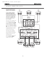
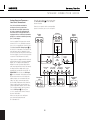
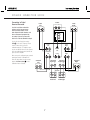
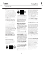
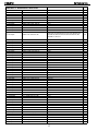
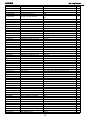
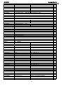
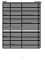
harman/kardon
HKSUB 12
Powered Subwoofer
SERVICE MANUAL
harman/kardon, Inc.
250 Crossways Park Dr.
Woodbury, New York 11797
Rev1 9/2004
HKSUB12
harman/kardon
CONTENTS
BASIC SPECIFICATIONS . . . . . . . . . . . . . . . . . . . . . . . . . .. . . . . ... . ... . . .. .. . .. . .. .. .. . . . . . 1
DETAILED SPECIFICATIONS . . . . . ………………... ……………. .. ………... . . .. . . . . .. . … . .2
CONTROLS & CONNECTIONS . . . . . . . . . . . . . .. . . . . . . . . … . . . . .. . . . . . . . . . .. . . .. . . . . 3
CONNECTION GUIDE………... . . . . . . . . . . . . .. . . . . . . . . …... . . . . . .. . . . . . . . . .. . . . . . . . . 5
CONFIGURING RECEIVER/PROCESSOR…………………..……………..……. . . . .. . .. . . . . . . 8
OPERATION……. . . . . .. . . . . . . . .. .. . . . .. .. . . . . …………………….……….. . . . .. . .. . . . . . . 9
BASIC TROUBLESHOOTING GUIDE………………………………………………………….. . . . .10
HKSUB 12 EXPLODED VIEW. . . . ………………... ……………. .. ………... . . .. . .. .. . . .. . … . 11
HKSUB 12 AMPLIFIER EXPLODED VIEW. . . . ………………... . .. ………... . . .. . .. .. . . .. . … . 12
HKSUB 12 BLOCK DIAGRAM . . . . . . . . . . . . . .. . . . . . . ……………… . . . . . . .. . .. .. . . . . . . 13
HKSUB 12 TEST PROCEDURE. .. . . . . . . . . . . . . . .. . . . . ……… ………….... . . . .. . .. .. . . . . . 14
HKSUB 12 PCB DRAWINGS. .. . . . . . . . . . . . . . .. . . . . ……… . …………. . . . . . . .. . .. .. . . . . . 15
HKSUB 12 ELECTRICAL PARTS LIST …………. .... . .. . . . . ………….…….. . . . . . .. . .. .. . . . . 17
HKSUB 12 MECHANICAL/PACKING PARTS LIST …………. .... . .. . . . . …... . . . . . .. . .. .. . . . . 20
HKSUB 12 IC – TRANSISTOR PINOUTS . … . . .. . . . . . . ………………….………... . .. .. . . . . . 21
HKSUB 12 SCHEMATIC DIAGRAMS . . . . . . . . .. .. .. .. . . . .. . ……………….……... . . . . . . . . . .22
HKSUB 12 PACKAGE………... . . . . . . . . . . . . .. . . . . . . . . …... . . . . . .. . . . . . . . . .. . . … . . . . .25
SPECIFICATIONS
Amplifier Power (RMS)
150 Watts
Driver
12" Polymer-coated-cone woofer
Inputs
Stereo Line Level, dedicated Subwoofer (LFE)
and Speaker Level with gold-plated 5-way binding posts
Outputs
Speaker Level with gold-plated 5-way binding posts
Low-Pass
Frequency Continuously variable from 50Hz – 150Hz
Frequency Response
25Hz – low-pass crossover setting
Dimensions
(H x W x D) 20-1/2" x 16" x 13-3/4"
(520mm x 401mm x 350mm)
Weight
40 lb/18kg
Occasional refinements may be made to existing products without notice but will always meet or exceed original specifications
unless otherwise stated.
1
HKSUB12
HK SUB12
harman/kardon
150W Powered Amplifier
LINE VOLTAGE
US 120vac/60Hz
Yes/No
Yes
Parameter
Amp Section
Type (Class AB, D, other)
Load Impedance (speaker)
Rated Output Power
THD@ Rated Power
THD @ 1 Watt
DC Offset
Specification
Damping factor
Hi/Lo Line
Unit
108-132
Vrms
Unit
D
4
150
0.08
0.15
5
D
Ohms
Watts
%
%
mV-DC
QA Test Limits Conditions
n/a
n/a
150
1
0.5
30
Nominal
1 input driven
22k filter
22k filter
@ Speaker Outputs
30
>100 DF
Input Sensitivity
Input Frequency
Line Input (L&R)
LFE (Sub) Input
Speaker/Hi Level Input
50
220
220
2.2
Signal to Noise
SNR-A-Weighted
SNR-unweighted
SNR @ 1W-unweighted
100 dBA
90 dBr
65 dBr
85
80
60
Residual Noise Floor
1.2 mVrms
Residual Noise Floor
0.8
Input Impedance
Line input L&R , LFE (Sub)
Speaker/Hi Level Input
10 K ohms
4.7 K ohms
Filters
Left & Right Low Pass fixed
LFE Low Pass fixed
Subsonic filter (HPF)
Notes
Normal Operation
Hz
mVrms
mVrms
Vrms
mVrms(max)
NA
±2dB
±2dB
±2dB
Notes
Measured at speaker terminals, Output
power 140 Watts THD 0.1 %
Nominal Freq.
To Rated Power
To Rated Power
To Rated Power
1 input driven
1 input driven
LFE input driven only
(-20 dB below Line In)...1 input driven
A-Weighting filter
22k filter
22k filter
3.0
rel. to rated power
rel. to rated power
rel. to 1W Output
Volume @max, using RMS reading
DMM/VOM (or A/P)
2.0
Volume @max, w/ A/P Swept Bandpass
Measurement (Line freq.+ harmonics)
n/a
n/a
Nominal
Nominal
130 Hz
220 Hz
22 Hz
----
±2dB
±2dB
±2dB
Limiter
YES
--
n/a
Features
LFE(Sub) Input
Volume pot Taper (lin/log)
ATO
YES
log
YES
--
functional
functional
functional
@ -3dB ref. 100Hz
@ -3dB ref. 100Hz
@ -3dB ref. 100Hz
BW Limited to 220 Hz
Signal Sensing (ATO)
ATO test Frequency
50 Hz
n/a
ATO Line Level
4.0 mV
2.0 - 8.0
ATO Speaker level input
40 mV
20 - 80
5 ms
functional
ATO Turn-on time
Auto Mute/ Turn-OFF Time
Power on Delay time
Transients/Pops
ATO Transient
Turn-on Transient
Turn-off Transient
15 minutes
10 - 25
functional
3 sec.
5 mV-peak
50 mV-peak
50 mV-peak
10
100
100
2mV@50Hz into Line Input w/ 1 ch.
driven
50mV@50Hz into Line Input w/ 1 ch.
driven
Amp connected and AC on, then input
signal applied
T before muting, after signal is removed
AC Power Applied
@ Speaker Outputs
@ Speaker Outputs
@ Speaker Outputs
AC Line cycled from OFF to ON
AC Line cycled from ON to OFF
12
250
@ nom. line voltage
@ nom. line voltage
Maximum allowable input power under
nominal Input voltage and frequency, HOT
or COLD operation.
150 Watts @ 4 Ohms nominal line voltage
Efficiency
Stand-by Input Power
Power Cons.@rated power
Protection
Short Circuit Protection
Thermal Protection
DC Offset Protection
Line Fuse Rating
US Version
10 Watts
230 Watts
YES
--
functional
Direct short at output
65 deg. C
YES
---
functional
functional
@1/8 max unclipped Power
DC present at Speaker Out leads
Temperature rise should not exceed 35K
rise
Relay or crowbar (for driver/fire protection)
Type-T or Slo Blo
External fuse with UL/SEMKO rated holder
3.15 Amps
2
HKP1209 SUB12 OM
10/23/02
9:28 PM
Page 8
HKSUB12
harman/kardon
AMPLIFIER PANEL CONTROLS AND CONNECTIONS
£ ¢∞ § ¶ •
¡ Speaker-Level Inputs
™ Speaker-Level Outputs
R
L
£ Line-Level Full-Range Inputs
LINE
LEVEL
IN
GREEN: ON
FILTER
RED: STAND-BY
AUTO
SUB
ON
™
OFF
¢ Line-Level Subwoofer (SUB) Input
ON
ª
‚
100Hz
L
∞ Phase Switch
§ Music-Sense On/Off Switch
R
¡
NORMAL
REVERSE
PHASE
IMPORTANT: CONNECT STRIPED WIRE TO RED (
) SPEAKE R TERMINAL.
50Hz
150Hz MIN
CROSSOVER
FREQUENCY
¶ LED Indicator
MAX
SUBWOOFER
LEVEL
• High-Cut (Low-Pass) Filter Switch
ª Crossover Frequency Control
‚ Subwoofer Level Control
⁄ Master Power Switch
¤ AC Power Cord
HKSUB 12
POWER
Made in China
⁄
AC 120V~60Hz
250 Watts
CAUTION
¤
RISK OF ELECTRIC SHOCK
DO NOT OPEN
¡ Speaker-Level Inputs: If your receiver
or amplifier does not have a line-level
subwoofer output, connect these binding
post terminals to the main left and right
speaker terminals of your receiver or
amplifier. Remember to maintain polarity
by connecting the (+) terminal on the
receiver/amplifier to the (+) terminal on the
HKSUB 12 subwoofer, and the (–) terminal on
the receiver/ amplifier to the (–) terminal on the
HKSUB 12 subwoofer.
™ Speaker-Level Outputs: If you are
using the Speaker-Level Inputs ¡ on
the HKSUB 12, connect these binding post
terminals to your front left and right speakers,
2
remembering to maintain polarity by connecting the (+) terminal on the HKSUB 12
subwoofer to the (+) terminal on the speaker, and the (–) terminal on the HKSUB 12
subwoofer to the (–) terminal on the speaker. If you are not using the Speaker-Level
Inputs ¡, connect your front left and
right speakers directly to your receiver
or amplifier. See pages 9 through 12 for
further information on speaker connections.
£ Line-Level Full-Range Inputs: Connect
the full-range, unfiltered line-level subwoofer
output or preamp output(s) of your receiver or
amplifier to these inputs. If your receiver does
not have a separate subwoofer output, use a
3
AMPLIFIER PANEL CONTROLS AND CONNECTIONS
Y-adapter (not supplied) to bridge the receiver’s
preamp output to the main amp input for that
channel, and connect the long end of the
adapter to the corresponding line-level input
on the HKSUB 12. If your receiver has only a
single subwoofer output, you may connect it
to either the left or right line-level input on the
HKSUB 12, and no Y-adapter is needed.
¢ Line-Level Subwoofer (SUB) Input:
Connect the filtered subwoofer output of a
receiver to this input. This input bypasses
the HKSUB 12’s internal crossover circuitry,
HKSUB12
harman/kardon
AMPLIFIER PANEL CONTROLS AND CONNECTIONS
and should only be used with a filtered signal. If your receiver does not have a filtered
subwoofer output, you should use the LineLevel Full-Range Inputs £ instead.
∞ Phase Switch: This switch determines
whether the HKSUB 12 subwoofer’s pistonlike action moves in and out in phase with
the main speakers. If the speakers are out
of phase, the sound waves produced by
the subwoofer will be cancelled out, reducing bass response. This phenomenon
depends in part on the relative placement
of the speakers in the room. In most cases,
the Phase Switch ∞ should be left in the
NORMAL position. However, it does no
harm to experiment with the Phase
Switch ∞, and you may leave it in the
position that maximizes bass response.
§ Music-Sense On/Off Switch: When
this switch is placed in the AUTO position,
and when the Master Power Switch ⁄ is
turned on, the HKSUB 12 will automatically
turn on or place itself in the Standby mode,
depending on whether it is receiving an audio
signal. When this switch is placed in the ON
position, the HKSUB 12 will remain on,
whether or not it is receiving an audio signal.
¶ LED Indicator: This LED indicates
whether the HKSUB 12 is in the ON
or STANDBY state when used with
the Music-Sense On/Off Switch § in
the AUTO position. The LED is lit green
to indicate that the HKSUB 12 is receiving
an audio signal and is turned on, and the
LED is lit red to indicate that no signal is
being received and the HKSUB 12 is in
Standby mode.
When the Music-Sense On/Off Switch
§ is in the ON position, the LED will be
lit green, whether or not an audio signal
is present.
When the Master Power Switch ⁄ is
turned off, the LED goes dark, no matter
which position the Music-Sense On/Off
Switch § is in.
• High-Cut (Low-Pass) Filter Switch:
Placing this switch in the ON position activates circuitry that filters out all audio input
signals above the setting of the Crossover
Frequency Control ª. This allows the
HKSUB 12 to focus its power on reproducing the low-frequency portion of the signal,
avoiding inefficiency and distortion. Engage
this filter when using the Speaker-Level
Inputs ¡, or when using the Line-Level
Full-Range Inputs £, unless your receiver or processor processes its line-level output using a low-pass filter. The filter has no
effect when the SUB Input ¢ is used.
¤ AC Power Cord: Plug this cord
into an active, unswitched electrical outlet
for proper operation of the HKSUB 12.
The cord should not be plugged into the
accessory outlets found on some audio
components.
ª Crossover Frequency Control: Adjust
this control to set the highest frequency the
HKSUB 12 will reproduce. You should
begin by setting it slightly above the
lowest frequency that your main speakers
are capable of reproducing. You may
safely adjust the crossover frequency
later as you listen to different program
materials. This control will have no effect if
you are using the Line-Level Subwoofer
(SUB) Input ¢, or if you have set the
High-Cut (Low-Pass) Filter Switch •
to the OFF position. See page 14 for
more information on adjusting the
crossover setting.
‚ Subwoofer-Level Control: Volume
may be adjusted using the SubwooferLevel Control. Turn the control clockwise
to increase the HKSUB 12’s volume, or
counterclockwise to decrease it.
⁄ Master Power Switch: Press this
rocker switch at the “•” mark to power-on
the HKSUB 12 subwoofer. The HKSUB 12
will then be either in the Standby mode or
completely on, depending on the position
of the Music-Sense On/Off Switch §.
4
AMPLIFIER PANEL CONTROLS AND CONNECTIONS
3
HKP1209 SUB12 OM
10/23/02
9:28 PM
Page 12
HKSUB12
harman/kardon
SPEAKER CONNECTION GUIDE
Analog Receiver/Processor –
Speaker-Level Connections
Use this installation method for
analog receivers or processors
that do not have digital processing
or bass-management programming,
and where the receiver/processor
does not have a subwoofer output,
or a volume-controlled preamp
(line-) level output:
Front
Left
–
Front
Right
Center
–
+
+
–
HKSUB 12
Subwoofer
L
Connect your receiver or amplifier’s front
left and right speaker terminals to the
left and right Speaker-Level Input ¡
terminals on the HKSUB 12 subwoofer
that are marked “High Level In.” Connect
the left and right Speaker-Level Output
™ terminals on the HKSUB 12 subwoofer
that are marked “High Level Out” to the
corresponding terminals on the back of
your front left and right speakers.
R
Receiver
or Amplifier
Connect your receiver or amplifier’s
center, surround, and surround back
speaker terminals to the corresponding
terminals on the back of your center
and surround speakers.
Front Left
Surround Left
When all connections have been made,
plug the AC Power Cord ¤ on the
subwoofer into an AC outlet.
Front Right
Center
Surround
Back Left
Surround
Back Right
–
+
–
Surround
Back Left
5
SPEAKER CONNECTION GUIDE
Surround Right
Surround
Right
Surround
Left
4
+
Surround
Back Right
+
HKSUB12
harman/kardon
SPEAKER CONNECTION GUIDE
Analog Receiver/Processor –
Line-Level Connections
Use this installation method for
analog receivers or processors
that do not have digital processing
or bass-management programming,
and where the receiver/processor is
equipped with an unfiltered subwoofer
output, or a volume-controlled preamp
(line-) level output:
When all connections have been made, plug
the AC Power Cord ¤ on the subwoofer
into an AC outlet.
Connect each speaker to the corresponding
speaker terminals on your receiver or amplifier.
Center
–
+
Front
Left
–
+
HKSUB 12
Subwoofer
Line-Level
Use the supplied RCA-type patch cord to
connect the line-level subwoofer output on
your receiver or amplifier to either the left or
right Line-Level Full-Range Input £ on
the HKSUB 12 subwoofer. Use both the left
and right inputs on the subwoofer if your
receiver or processor has both left and right
line-level outputs. (You will need to purchase
a second 15-foot interconnect cable.)
L
R
Front
Left
If your receiver is equipped with line-level outputs but does not have a separate subwoofer
output, use a Y-adapter (not supplied) to
bridge the receiver’s preamp output to the
main amp input for that channel, and connect
the long end of the adapter to the corresponding line-level input on the HKSUB 12.
IMPORTANT: Do not use the SUB Input
¢ on the subwoofer with analog receivers
or processors that have a full-range subwoofer output, such as models that have
Dolby Pro Logic* surround processing,
but not Dolby Digital processing. However,
if your analog receiver or processor has
a filtered subwoofer output, such as some
THX®-certified models, you may connect
it to the SUB Input ¢. Consult your
receiver’s or processor’s owner’s manual
for more information.
Front
Right
–
+
Surround
Left
Subwoofer
Out
Center
Surround
Back Left
Surround
Back Right
Receiver or Amplifier
Surround
Left
–
+
Surround
Back Left
Surround
Back Right
Front
Right
Surround
Right
Surround
Right
–
+
Make sure that you have configured
your surround sound processor
for “Subwoofer On.”
6
SPEAKER CONNECTION GUIDE
5
HKSUB12
harman/kardon
SPEAKER CONNECTION GUIDE
Connection to Digital
Receiver/Processor
Use this installation method for
analog receivers or processors
that have Dolby Digital, DTS or
other digital surround decoders and
bass-management programming,
or analog receivers or processors
that have a filtered subwoofer output:
Center
–
+
Front
Left
–
+
Front
Right
–
+
HKSUB 12 Subwoofer
SUB
LINE
LEVEL
IN
R
L
Use the line-level input jack marked
SUB ¢ for the Low-Frequency Effects
channel. Connect this jack to the
subwoofer output or LFE output on your
receiver or amplifier. Connect each speaker
to the corresponding speaker terminals on
your receiver or amplifier.
Front
Left
Front
Right
SUB/LFE
Out
Surround
Left
Center
Surround
Right
Make sure you’ve configured your surround
sound processor for “Subwoofer On.”
When all connections have been made,
plug the AC Power Cord ¤ on the
subwoofer into an AC outlet.
Surround
Left
–
+
Surround
Back
– Left
+
Surround
Back Right
–
+
Receiver
or
Amplifier
–
+
Surround
Back Left
7
6
SPEAKER CONNECTION GUIDE
–
+
Surround
Back Right
Surround
Right
–
+
HKSUB12
harman/kardon
CONFIGURING YOUR RECEIVER OR PROCESSOR
Configuring Your Receiver or
Processor
Modern surround sound receivers and
processors are sophisticated machines
that enable you to tailor the receiver’s
performance to match your loudspeakers
by programming the bass-management
function of the receiver. Bass management
ensures that the lowest and most powerful
frequency signals will be sent only to those
loudspeakers capable of reproducing them
without distortion. This is a simple matter of
selecting the correct speaker “size” on the
receiver to match the frequency range of
your speakers.
In the case of the HKSUB 12 subwoofer,
it is important to make sure that the
Subwoofer channel is enabled by setting it to
ON, SUB, LFE or L/R + LFE,
depending upon the capabilities of your
receiver. If you have full-range speakers for
your front left and right channels, you may
wish to configure your receiver to send only
the LFE signal to the HKSUB 12. For maximum bass performance, you may prefer to
send both the L/R and LFE low-frequency
signals to the HKSUB 12. Consult the
owner’s manual for your receiver or processor
for additional information.
8
CONFIGURING YOUR RECEIVER OR PROCESSOR
7
HKSUB12
harman/kardon
OPERATION
Power
Press the Master Power Switch ⁄
(marked Power) at the “•” (On) marking.
The HKSUB 12 subwoofer will automatically
turn on or go into Standby mode, depending
on whether or not a signal is being sent to it
by your receiver or surround processor, and
provided that the Music-Sense On/Off
Switch § is moved to the left so that it is
in the AUTO position.
When your receiver or amplifier is off, or is
not sending program material to the subwoofer, the subwoofer will be in Standby
mode and the LED Indicator ¶ on the
amp panel will turn red. When the subwoofer
senses an audio signal, it will automatically
turn on and the LED Indicator ¶ will turn
green. If the subwoofer does not sense a
signal after approximately fifteen minutes,
it will automatically go into Standby mode.
When the Music-Sense On/Off Switch §
is switched to the ON position, the subwoofer will remain on, whether or not program material is playing.
When you are away from home for
an extended period of time, switch the
Master Power Switch ⁄ to the OFF
position to prevent accidental activation of
the HKSUB 12.
Volume
Volume may be adjusted using the
Subwoofer Level Control ‚, as
shown. Turn the control knob clockwise
to increase the volume of the subwoofer,
and counterclockwise to decrease the
subwoofer’s volume.
Subwoofer
Level
MIN
Subwoofer
Level
MIN
MAX
The Subwoofer Level Control ‚ adjusts
the volume of the subwoofer relative to the
rest of the system. Proper level adjustment
depends on several variables such as room
size, subwoofer placement, type of main
speakers and listener position. Adjust the
subwoofer level so that the volume of the
bass information is pleasing to you.
Additional Bass Adjustments
In addition to the volume adjustments
described above, the HKSUB 12 subwoofer
includes a Crossover Frequency Control
ª, a Filter Switch • and a Phase
Switch ∞ that can be used to adjust the
bass response to suit your listening environment or taste.
The Crossover Frequency Control ª
determines the highest frequency at which
the subwoofer reproduces sounds when the
Speaker-Level Inputs ¡ or Line-Level
Full-Range Inputs £ are used. Consult
the owner’s manual for your main speakers
to determine the lowest frequency they are
capable of reproducing, and set this control
slightly above that frequency. For example, if
the specified frequency response for your
main speakers is 80Hz – 20kHz, then set
the Crossover Frequency Control ª
slightly to the left of the 100Hz marking
on the HKSUB 12’s amplifier panel.
The Crossover Frequency Control ª has
no effect when the SUB Input ¢ is in use,
or when the High-Cut (Low-Pass) Filter
Switch • is in the OFF position.
The High-Cut (Low-Pass) Filter Switch
• limits the frequencies of the audio signal
inputted to the subwoofer to the low
MAX
9
OPERATION
8
frequencies that the subwoofer reproduces
best. This allows the subwoofer to perform
more efficiently and with superior bass
reproduction, minimizing distortion that might
occur if the subwoofer attempted to reproduce higher frequencies. This switch should
be left in the ON position, except:
1. When the SUB Input ¢ is being used,
in which case it has no effect, or
2. When the Speaker-Level Inputs ¡ or
the Line-Level Full-Range Inputs £ are
being used with a crossover or filter aboard
the receiver or processor.
In these two circumstances, place the switch
in the OFF position.
If your receiver or processor allows you to
select the crossover frequency for the main
speakers, choose the setting just above the
lowest frequency the main speakers are
capable of reproducing. This will send the
low-frequency portion of the signal to your
HKSUB 12, which is best able to reproduce
these frequencies with greatest efficiency
and minimal distortion. In this case, you may
use the SUB Input ¢ connection, or if
that is not compatible with your receiver or
processor, place the High-Cut (Low-Pass)
Filter Switch • in the OFF position in
order to avoid filtering the signal twice, which
may lead to signal loss and distortion.
In most situations, the Phase Switch ∞
should be left in the NORMAL position.
If you suspect that the subwoofer is playing
out of phase with the other speakers, which
would tend to diminish bass response, try
placing this switch in the REVERSE
position. There is no harm in experimenting,
and you may return the switch to the
NORMAL position at any time.
If you rearrange your room and reposition
the speakers, it would be a good idea to
check whether they are in phase by
flipping this switch.
HKSUB12
harman/kardon
TROUBLESHOOTING
SYMPTOM
SOLUTION
If you used the
• Check that receiver/amplifier is on and a source is playing.
Speaker-Level Inputs ¡ • Check that the HKSUB 12 is plugged into an active electrical outlet and is switched on using the Master
and there is no sound
Power Switch ⁄.
from any of the speakers: • Check all wires and connections between receiver/amplifier and speakers. Make sure all wires are connected.
Make sure none of the speaker wires are frayed, cut, punctured or touching other wires or terminals,
which may cause a short.
• Review proper operation of your receiver/amplifier.
If there is low (or no)
bass output:
• Make sure that all speakers have been correctly connected in phase, with the (+) terminal on the speaker
connected to the (+) terminal on the receiver/amplifier, and the (–) terminal on the speaker to the (–) terminal
on the receiver/amplifier.
• Check that the HKSUB 12 is plugged into an active electrical outlet and is switched on using the Master
Power Switch ⁄.
• Slowly turn the Subwoofer Level Control ‚ clockwise until you begin to hear the desired amount of bass.
• If you are using either the Line-Level Full-Range Inputs £ or the Line-Level Subwoofer (SUB)
Input ¢, make sure you have properly configured your receiver or processor to enable its subwoofer output.
• If you are using the Line-Level Full-Range Inputs £, try adjusting the crossover setting using the
Crossover Frequency Control ª.
• If you are using either the Speaker-Level Inputs ¡ or the Line-Level Full-Range Inputs £
with a full-range output from your receiver or processor, switch the High-Cut (Low-Pass) Filter Switch •
to the ON position.
• Switch the Phase Switch ∞ from the NORMAL to the REVERSE position, or vice versa.
• Review proper operation of your receiver or processor and amplifier.
10
TROUBLESHOOTING
9
HKSUB12
HKSUB 12 MECHANICAL PARTS LIST
Part Number
Description
1
sz5999
logo
1
2
x1205000
Grille
1
3
338-RUB-00123
Grille cups
6
4
352-FM05034D482
Foot/Front Baffle Screws
4
5
XC125009
1
6
30PF14FM-DW04
Front baffle
Woofer w/gasket
DCR = 3.3 ohms
7
352-CM04020D202
Woofer Screws
8
8
WI5334-1
rubber feet
4
9
WI5321-B
harman/kardon
Qty
12
1
plastic feet
4
10 Not for Sale
Cabinet w/ port tube
1
11 Not for Sale
Amplifier
1
12 352-AM0402D210
Amplifier screws
10
11
10
5
9
6
4
8
TO SERVICE THE HKSUB 12 SUBWOOFER
3
1)
2)
3)
4)
5)
6)
Remove the grille.
Extract (6) rubber grille retainers; this can be accomplished by carefully pulling them out of the cavities with long-nosed pliers or
similar tool.
Remove the (6) Phillips screws that are now exposed.
Remove the front baffle.
Remove the (8) screws that secure the woofer (the screws may have a small adhesive pad atop each screw – they will have to be
moved or removed); remove the woofer and unplug the wires from the terminals.
To service the amplifier, remove the (10) Phillips screws at the rear of the enclosure, and pull the amplifier out of the back.
11
HKSUB12
harman/kardon
HKSUB12 AMPLIFIER EXPLODED VIEW
12
HKSUB12
harman/kardon
HKSUB 12 BLOCK DIAGRAM
13
HKSUB12
harman/kardon
Test Set Up and Procedure
Equipment needed:
• Function/signal generator/sweep generator
• Integrated Amplifier
• Multimeter
• Speaker cables
Initial Control Settings:
• Power Switch OFF; Filter OFF
• Crossover Frequency 150Hz (Full CW)
• Level MIN (Full CCW)
• Phase, Standby switches do not matter
General Unit Function (UUT = Unit Under Test)
1) From the signal generator, connect one line level (RCA) cable to the Subwoofer Line Level Input jacks L/R
on the UUT. Use a Y-cable from a mono source if necessary to connect to both inputs. Do not connect to
the single, purple SUB input.
2) Turn on generator; adjust to 90mV, 50 Hz.
3) Plug in UUT; turn the power switch ON. LED should switch from Red to Green. Turn LEVEL control full
clockwise (MAX)
4) LED should Green; immediate and vigorous bass response should be heard and felt from port tube
opening.
5) Turn off generator, turn LEVEL control full counterclockwise (MIN), and disconnect RCA cable.
6) Connect one pair of speaker cables to Speaker Level input terminal (IN) on UUT. Cables should be
connected to an integrated amplifier fed by the signal generator.
7) Turn on generator and adjust so that speaker level input at the amplifier is 1.5V, 50 Hz. Turn LEVEL control
full clockwise.
8) Green LED should light; immediate and vigorous bass response should be heard and felt from the port
tube opening.
Sweep Function
1) Follow steps 6-8 above, using a sweep generator as a signal source.
2) Sweep generator from 20Hz to 300Hz. Listen to the cabinet and drivers for any rattles, clicks, buzzes or
any other noises. If any unusual noises are heard, remove woofers and test.
Driver Function
1) Remove woofer from cabinet (instructions on exploded view drawing); detach + and - wire clips.
2) Check DC resistance of woofer; it should be 3.3 ohms ±10%
3) Connect a pair of speaker cables to driver terminals. Cables should be connected to an integrated amplifier
fed by a signal generator. Turn on generator and adjust so that speaker level output is 5.0V.
4) Sweep generator from 20Hz to 1kHz. Listen to driver for any rubbing, buzzing, or other unusual noises.
14
HKSUB12
harman/kardon
15
HKSUB12
harman/kardon
16
HKSUB12
harman/kardon
HKSUB 12 Electrical Parts List
PART NO.
DESCRIPTION
REFERENCE DESIGNATOR
QTY
110-12472j52
110-14103j26
110-14222j26
110-14432j26
110-14472j26
110-16102j26
Resistor4.7K 1/2W ±5% CF
Resistor 10K 1/4W ±5% CF
Resistor 2.2K 1/4W ±5% CF
Resistor 4.3K 1/4W ±5% CF
Resistor 4.7K 1/4W ±5% CF
Resistor 1K 1/6W ±5% CF
R201,202
R503,504,510
R511
R506
R505
R153,213,214,215,254
2
3
1
1
1
5
110-16103j26
Resistor 10K 1/6W ±5% CF
R128,130,149,150,209,212,216,217,218,220,221,222,
225,228,229,230,232,234,235,240,248,260,270,305,
306,308,311,314,319
29
110-16104j26
110-16105j26
110-16122j26
110-16124j26
110-16151j26
110-16153j26
110-16154j26
110-16182j26
110-16183j26
110-16203j26
110-16205j26
110-16221j26
110-16222j26
110-16223j26
110-16303j26
110-16333j26
110-16393j26
110-16472j26
110-16473j26
110-16474j26
110-16512j26
110-16562j26
110-16621j26
110-16682j26
110-16751j26
110-16755j26
110-16913j26
116-161002f26
116-161102f26
116-162200f26
116-162202f26
110-20332jk3
113-50s68j00
115h203b201
115h503a102
116-201001jk3x
116-304700jk2x
1091ttc802j0
Resistor 100K 1/6W ±5% CF
Resistor 1M 1/6W ±5% CF
Resistor 1.2K 1/6W ±5% CF
Resistor 120K 1/6W ±5% CF
Resistor 150Ω 1/6W ±5% CF
Resistor 15K 1/6W ±5% CF
Resistor 150K 1/6W ±5% CF
Resistor 1.8K 1/6W ±5% CF
Resistor 18K 1/6W ±5% CF
Resistor 20K 1/6W ±5% CF
Resistor 2M 1/6W ± CF
Resistor 220Ω 1/6W ±5% CF
Resistor 2.2K 1/6W ±5% CF
Resistor 22K 1/6W ±5% CF
Resistor 30K 1/6W ±5% CF
Resistor 33K 1/6W ±5% CF
Resistor 39K 1/6W ±5% CF
Resistor 4.7K 1/6W ±5% CF
Resistor 47K 1/6W ±5% CF
Resistor 470K 1/6W ±5% CF
Resistor 5.1K 1/6W ±5% CF
Resistor 5.6K 1/6W ±5% CF
Resistor 620Ω 1/6W ±5% CF
Resistor 6.8K 1/6W ±5% CF
Resistor 750Ω 1/6W ±5% CF
Resistor 7.5M 1/6W ±5% CF
Resistor 91K 1/6W ±5% CF
P.T.C. 10K 1/6W ±1% MF
P.T.C. 11.0K 1/6W ±1% MF
P.T.C. 220Ω 1/6W ±1% MF
P.T.C. 22.0K 1/6W ±1% MF
Resistor 3.3K 2W ±5%
Cement Res. 0.068Ω 5W ±5%
Variable Res. 20KB/2
Variable Res. 50KA
Metal Res. 1.00K 2W ±5%
Metal Res. 470Ω 3W ±5%
Resistor TTC-802(JS) NTC
R122,126,231,263,266,307
R259
R265
R233
R253
R107
R252
R145
R262
R237,238,309
R257
R144
R102
R247,255,256,316
R223,224
R310
R151
R200,207,258
R106,129,219,249,250,251,264
R127,312
R210,211
R152
R160
R226,227
R315
R313
R203,204,205,206
R301,303
R302
R317
R318
R134
R147
VR202
VR201
R148
R501,502
TH1
6
1
1
1
1
1
1
1
1
3
3
1
1
4
2
1
1
3
7
2
2
1
1
2
1
1
4
2
1
1
1
1
1
1
1
1
2
1
Metallze Cap. 0.15U 63V ±5% MSC
Metallze Cap. 0.22uF 63V ±5% MSC
C221,222
C218
2
1
Resistors
Capacitors
129-a154j633
129-a224j633
17
HKSUB12
harman/kardon
PART NO.
DESCRIPTION
REFERENCE DESIGNATOR
QTY
1302b101k503
130-2b221k503
130-2b470k503
Disc Cap. 100P 50V ±10%
Disc Cap. 220P 50V ±10%
Disc Cap. 47P 50V ±10%
3
12
1
130-2f104z503
Disc Cap. 0.1U 50V +80/-20%
132-103j503
132-103ja03
132-104ja03
132-183j503
132-223ja03
132-273ja03
132-473j503
132-563j503
132-823j503
135-3105m50
135-3106m50
135-3107m10
135-3107m16
135-3107m35
135-3225m50
135-3226m16
135-3226m50
135-3227m16
135-3476m16
132-103kb00
1385478m63
Mylar Cap. 0.01U 50V ±5%
Mylar Cap. 0.01uf 100V ±5%
Mylar Cap. 0.1UF 100V ±5%
Mylar Cap. 0.018uF 50V ±5%
Mylar Cap. 0.022uF 100V ±5%
Mylar Cap. 0.027UF 100V ±5%
Mylar Cap. 0.047U 50V ±5%
Mylar Cap. 0.056U 50V ±5%
Mylar Cap. 0.082U 50V ±5%
Electrolytic Cap. 1U 50V ±20%
Electrolytic Cap. 10uF 50V ±20%
Electrolytic Cap. 100U 10V ±20%
Electrolytic Cap. 100uF 16V ±20%
Electrolytic Cap. 100U 35V ±20%
Electrolytic Cap. 2.2U 50V ±20%
Electrolytic Cap. 22U 16V ±20%
Electrolytic Cap. 22U 50V ±20%
Electrolytic Cap. 220U 16V ±20%
Electrolytic Cap. 47U 16V ±20%
Mylar Cap. 0.01uF 200V ±10%
Electrolytic Cap.4700u 63v 20%
C302,303,306
C200,204,205,207,208,210,211,212,214,220,230,237
C229
C107,117,122,144,232,242,245,246,252,254,256,320,
322
C305,317
C103,104
C123,503,504
C223
C215
C143
C224
C216
C217
C228
C201,202,206,213,219,231,241,243,251,253,319,321
C114,115
C234
C507,508
C509
C304
C225,505,506
C118,233
C318
C500
C501,502
Transistor 2SC1815GR
Transistor 2SC2235Y
Transistor 2SA1015GR
Transistor 2N5551
Transistor 2N5401 AI-PNP 350V
Diode 1N4148
Zener Diode 3.3V 1/2W
Zener Diode 6.2V 1/2W
Zener Diode 16V 1/2W
I.C. OPA 4558D
I.C TL074CN ST
Transistor TIP31C SGS
Transistor TIP32C SGS
LED 204HGW 3
Diode 6A 800V KBU606G
Diode 1n4004
Q108,109,113,201,206,207,208,301,302
Q111
Q101,107,112
Q114,115
Q503
D102-105,143,201-208,214,215,216,301,302
D213
D101
D502
U203
U201,202,301
Q501
Q502
D209
D501
D110,504
9
1
3
2
1
18
1
1
1
1
3
1
1
1
1
2
Inductor 10W AI YT-C3104-005
Relay RWH-SH-124D (1600 ohm)
JACK RCA-326
SPK JK BP 8PIN
SWITCH SLIDE 6PIN MS7210V
TRANSFER POWER 120V/60Hz
AC Line Cord SVT FT-2
Fuse 3.15A 250V 30mm UL/CSA
Fuse Holder HTB-32I 30mm UL/CSA
PUSH SW BR12C11S
FB1,2
RL1
JK201
JK202
SW201,202,203
T501
2
1
1
1
3
1
1
1
1
1
13
2
2
3
1
1
1
1
1
1
1
12
2
1
2
1
1
3
2
1
1
2
Semiconductors
192027c1815gr
192027c2235y
192028a1015gr
1921672n5551
1921682n5401
197131n4148
199-15000335
199-15000625
199-15001605
19006m4558d
19016tl074cn
192161tip31c
192162tip32c
19510204hgw
19700kbu606g
197101n4004
Miscellaneous
1201000003
171urwh124d
1740rca326p
17420810360g
180tms7210v
150r4055900a
152u602015
154k31505t0
15563032i
180pbr12c11s
F501
for F501
SW501
18
HKSUB12
harman/kardon
PART NO.
DESCRIPTION
REFERENCE DESIGNATOR
16250129001
1751b08v01
1751d02v01
1751d03v01
16210082007
176wjce1
193201815t2
600b8401200
602p4300800
602p8300800
603r8807000
606p8301000
607c8301208
607p4300800
607p8300800
650sub240
653hsqlc1004
700kb800
700rc800a
707ac800
723a125
723a125-1
723b125
723b125-1
723d125
723i125
723j125
860a125
W201
CABLE ASS'Y 120mm AWG28 WHT
W202
8 PIN PITCH=2.0mm
M100
2PIN PITCH=3.96mm
M500
3PIN PITCH=3.96mm IST-VH
SW TO FUSE HOLDER
WIRE RED AWG18 80mm#1015 8mm
CLOSE END TERMINAL CE-1
CERAMIC ISOLATOR FOR Q10,1
SCREW TO R/C ψ4*12
SCREW PCB TO BRKT-4
M3*8
SCREW R/P TO BRKT-2,TO 650pf8-bk- 2 M3*8
SCREW TO XFORMER
M8*70
SCREW SPK-2,RCA-1 ψ3*10
SCREW H/S TO ID150-1
ψ3*12
SCREW PCB TO H/S-2
ψ3*8
SCREW R/P TO H/S-2
ψ3*8
PCB STAND L TYPE t=1.6mm S.P.C.C
HEAT SINK
KNOB 46077-W P.V.C.
REAR CABINET 268*213*102 A.B.S UL
BUSHING 4K-4 NO-BB
GASKET 213*15*2.0mm
GASKET213*15*1.0t
GASKET 238*15*2.0mm
GASKET238*15*1.0t
TO PRE PCB-1 GASKET 170*5*1t
TO LINK WIRE-1 GASKET150*15*1t UL
TO SPK WIRE
GASKET 225*15*1t UL
TO SPEAKER
QTY
1
1
1
1
2
4
4
4
3
2
2
2
2
2
2
2
2
2
Power Amp Module PW150D (1010DS150-1)
Resistors
118-12061001j
118-12061002j
118-120610r0j
118-12061201j
118-12062002j
118-12062201j
118-12062701j
118-12063000j
118-12063301j
118-12063902j
118-12064700j
118-12064701j
118-12064702j
118-12064704j
118-120647r0j
R2,11,29,30
R7,9,25
R22,23
R31-46
R26
R6,13,16
R10
R24
R14,15,27,28
R3
R8
R1,5,12
R17
R4
R20,21
RES, 1.00K 1206 5%
RES, 10.0K 1206 5%
RES, 10.0 ohms 1206 5%
RES, 1.20K 1206 5%
RES, 20.0K 1206 5%
RES, 2.20K 1206 5%
RES, 2.70K 1206 5%
RES, 300.0 ohms 1206 5%
RES, 3.30K 1206 5%
RES, 39.0K 1206 5%
RES, 470 ohms 1206 5%
RES, 4.70K 1206 5%
RES, 47.0K 1206 5%
RES, 4.70M 1206 5%
RES, 47.0 ohms 1206 5%
4
3
2
16
1
3
1
1
4
1
1
3
1
1
2
C4
C5
C6
C2,3,7,8,9,10,11,15
C13
C1
CAP,CA
CAP,CA
CAP,CA
CAP,CA
CAP,CA
CAP,NP
1
1
1
8
1
1
Capacitors
141-c0101k50
141-c0220k50
141-c0561k50
141-c6104m50
141-c7223k50
141-d7104ka0
19
100pF 50V 10% 1206 NP0
22pF 50V 10% 1206 SMT NPO
560pF 50V 10% 1206 NPO
0.1uF 50V 20% 1206 Z5U
0.022uF 50V 10% 1206 X7R
0.1uF 100V 10% 1210 X7
HKSUB12
harman/kardon
PART NO.
DESCRIPTION
REFERENCE DESIGNATOR
QTY
128e106ma01
141-d7104kb0
C16,17
CAP,E NP 10uF 100V 20%
CAP,NP 0.1uF 200V 10% 1210 X7
2
1
IC1
Q1,4,5
Q2,8
Q7,9
Q3,6
D1,2,3,4,5,6
Z1,2
Z5,6
Z3,4
Q10
Q11
SMD I.C. TL072CDT SGS Dual Op-Amp
TRANS, NPN 50V 0.15A 2SC2412K
TRANS, NPN 120V 0.05A 2SC3906K
TRANS, PNP 50V 0.15A 2SA1037K
TRANS, PNP 120V 0.05A 2SA1514K
Diode RLS4148
ZENER 5.6V 5% PHILIPS BZX84-C5 V6
ZENER 12V 5% PHILIPS BZX84-C12
ZENER 15V 5% PHILIPS BZX84-C15
FET IRF9640 IR P-CH TO220
FET IRF640 IR N-CH TO-220
1
3
2
2
2
6
2
2
2
1
1
L1
L2
PCB TO H/S-2,PCB TO PCB/H-4
TO HSQLC1004/ID150-1
Wafer 40PIN PITCH=2.54mm HR2*40
Ferrite core LS-A6206-ST EFD-30
Inductor 35uH
SCREW 3*8
SCREW M3*12
1
1
6
1
Semiconductors
19016tl072dts
19209124126qs
19209139066rs
19209210376qs
19209215146rs
19703rls4148s
199-15000563s
199-15001203s
199-15001503s
192232irf9640
192233irf640
Miscellaneous
1759f40hr2
12214121m4191
12214350j4180
06-t3085020
06-t31207
HKSUB 12 Mechanical/Packing Parts List
Part Number
Description
Qty
Not for Sale
30PF14FM-DW04
sz5999
x1205000
338-RUB-00123
XC125009
352-CM04020D202
352-FM05034D482
352-AM0402D210
WI5321-B
WI5334-1
Amplifier
Woofer w/gasket DCR = 3.3 ohms
logo
Grille
Grille cups
Front baffle
Woofer Screws
Foot/Front Baffle Screws
Amplifier screws
plastic feet
rubber feet
1
1
1
1
6
1
8
4
10
4
4
wb6390
ai5271
405-000-00227
wp5375
sal5044
Outer carton
Owner's manual
warranty card
Packing foam
cable
1
1
1
2
1
20
HKSUB12
harman/kardon
Integrated Circuit Diagrams
OPAMP, QUAD 14P DIL TL074
U201, 202, 301
4558 / TLO72 DUAL OP AMP,
U203, IC1
MOSFET, TO220
IRF640, 9640
Q11, 10
TIP31C NPN,
TIP32C PNP,
Q501,502
1. G
2. D
3. S
TRANS, PNP, 2N5401
TO-92,
Q503
1
2
3
TRANS, NPN, 2N5551
Q114,115
B
C
E
TRANS, PNP,
2SA1015GR
TRANS, NPN, 2SC1815GR
2SC2235,
Q108,109,111,113,201,206-208,301,302
Q101,107,112
21
HKSUB12
harman/kardon
22
HKSUB12
harman/kardon
23
HKSUB12
harman/kardon
24
HKSUB 12
®
Packaging
WARRANTY
CARD
405-000-00227
OWNER'S
MANUAL
ai5271
PACKING
FOAM
wp5375
PACKING
FOAM
wp5375
OUTER
CARTON
wb6390
CABLE
sal5044
25