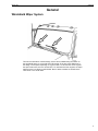
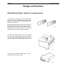
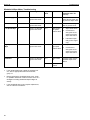
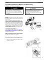
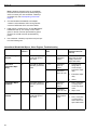
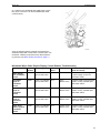
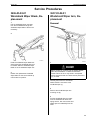
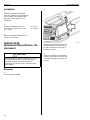
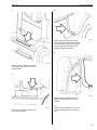
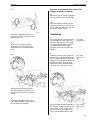
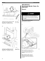
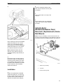
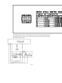
1
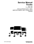
Service Manual
Trucks
Group
363–500
Windshield Wiper System
VN, VHD
PV776-TSP143133
Foreword
The descriptions and service procedures contained in this manual are based on designs and methods studies carried out up to August 2000.
The products are under continuous development. Vehicles and components produced
after the above date may therefore have different specifications and repair methods.
When this is believed to have a significant bearing on this manual, supplementary service bulletins will be issued to cover the changes.
The new edition of this manual will update the changes.
In service procedures where the title incorporates an operation number, this is a reference to an S.R.T. (Standard Repair Time).
Service procedures which do not include an operation number in the title are for general information and no reference is made to an S.R.T.
The following levels of observations, cautions and warnings are used in this Service
Documentation:
Note: Indicates a procedure, practice, or condition that must be followed in order to
have the vehicle or component function in the manner intended.
Caution: Indicates an unsafe practice where damage to the product could occur.
Warning: Indicates an unsafe practice where personal injury or severe damage to the
product could occur.
Danger: Indicates an unsafe practice where serious personal injury or death could occur.
Volvo Trucks North America, Inc.
Greensboro, NC USA
Order number: PV776-TSP143133
© 2000 Volvo Trucks North America, Inc., Greensboro, NC USA
All rights reserved. No part of this publication may be reproduced, stored in
retrieval system, or transmitted in any forms by any means, electronic, mechanical, photocopying, recording or otherwise, without the prior written
permission of Volvo Trucks North America, Inc..
Contents
General .................................................................................................... 3
Windshield Wiper System ..................................................................... 3
Tools ........................................................................................................ 5
Special Tools ......................................................................................... 5
Design and Function ............................................................................. 7
Windshield Wiper System Components .................................................. 7
The Windshield Washer System ......................................................... 8
Graphic Display Control Buttons ......................................................... 10
Troubleshooting ...................................................................................
Work Practices ....................................................................................
Using the VCADS Pro Tool .................................................................
Windshield Washer Pump, Troubleshooting ........................................
Windshield Wiper Stalk Switch, Troubleshooting ................................
Windshield Wiper Motor, Troubleshooting ...........................................
Intermittent Windshield Wipers, Troubleshooting ................................
Models with Volvo Engines ...............................................................
Intermittent Windshield Wipers, Troubleshooting ................................
Models with Non-Volvo Engines ........................................................
Windshield Wiper Stalk/ Graphic Display Control Buttons, Troubleshooting ..........................................................................................
13
13
13
14
16
19
21
21
24
24
Service Procedures .............................................................................
Windshield Wiper Blade, Replacement ...............................................
Windshield Wiper Arm, Replacement .................................................
Windshield Wiper Module, Replacement ...........................................
Windshield Wiper Switch, Replacement .............................................
Windshield Wiper Motor, Replacement ...............................................
Windshield Wiper Motor and Linkage Assembly, Replacement .........
Windshield Washer Pump, Replacement ............................................
Windshield Washer Fluid Fill Bottle, Replacement .............................
Windshield Washer Fluid Filter, Replacement ....................................
Windshield Washer Check Valve, Replacement .................................
Windshield Washer Fluid Reservoir, Replacement (Battery Box
Mount) ..................................................................................................
Windshield Washer Fluid Reservoir, Replacement (Frame Rail
Mount) ..................................................................................................
29
29
29
30
31
33
34
40
41
42
42
26
42
43
Feedback
Foldout A Windshield Wiper System
Foldout B Windshield Wiper System
Foldout C Windshield Wiper Stalk/ Graphic Display Control Buttons
Operation Numbers
1
2
Group 36
General
General
Windshield Wiper System
W3004393
This service information contains design, service and troubleshooting information on
the windshield wipers. It covers VN and VHD models. There are some differences in
the design of the wipers depending on engine model. For vehicles with Volvo engines,
the wiper electronics are in the Vehicle ECU. For vehicles with other engines, the wiper
electronics are in a Wiper Control Module. Both of these modules are located in the
TEC center in the center dash.
3
4
Group 36
Tools
Tools
Special Tools
The following special tools may be needed when troubleshooting the Windshield Wiper
System. When ordering these tools from Kent-Moore (800)-328–6657 or Volvo, quote
the specified number.
Note: For VCADS Pro tooling see most current VCADS Pro user manual.
W3004327
J-41133
5-pin breakout harness (Kent-Moore)
J-39200
Digital Multimeter
(Kent-Moore)
J-44567
Probe Adapter (Kent
Moore)
9998551
60-Pin breakout box
(Volvo)
J-43234
Adapter (Kent-Moore)
J-43340
Overlay for 60-pin
breakout box (KentMoore)
5
6
Group 36
Design and Function
Design and Function
Windshield Wiper System Components
A windshield wiper stalk switch controls the windshield
wiper system used on VN/VHD series vehicles. Control
buttons for the instrument cluster graphic display are integrated into this switch.
Intermittent windshield wipers are pre-set to make a single sweep every 10 seconds. The interval can be set to
between 1 and 10 seconds by moving the windshield
wiper stalk to the intermittent position, then to off, then to
intermittent again when another sweep is desired.
W3004341
The intermittent windshield wiper function is controlled in
one of two ways, depending on the engine. On vehicles
with Volvo engines, the Vehicle Electronic Control Unit
(VECU) and intermittent windshield wiper relay are used.
W2002673
On vehicles with Cummins or Detroit engines, a windshield wiper control module is used.
W3003803
7
Group 36
Design and Function
The Windshield Washer System
W3004333
Fig. 1: Frame Rail Mount
8
1
Windshield Washer Fluid Fill Bottle
2
Windshield Washer Pump
3
Windshield Washer Fluid Filter
4
Windshield Washer Check Valve
5
Windshield Washer Fluid Reservoir (Battery Box Mount)
Group 36
Design and Function
W3004334
Fig. 2: Battery Box Mount
1
Windshield Washer Fluid Fill Bottle
2
Windshield Washer Pump
3
Windshield Washer Fluid Filter
4
Windshield Washer Check Valve
5
Windshield Washer Fluid Reservoir (Frame Rail Mount)
9
Group 36
The windshield washer fluid is added to the system at the
fill bottle located on the left side cowl (1). Fill and vent
hoses run from the fill bottle to the fluid reservoir. The
“battery box mount” fluid reservoir (5) is most commonly
used. This is the mounting location on all VN series. The
location is the same on the VHD series when the battery
location is the same as VN. On the VHD series with alternate battery locations, the “frame rail mount” fluid
reservoir (6) is located on the top of the left frame rail.
Design and Function
T3008838
Low Washer Fluid Level Icon
The windshield washer pump (2) is mounted to the fluid
reservoir with the tip submerged in windshield washer
fluid. Whenever windshield “wash” is requested, the
pump delivers windshield washer fluid via hoses first to
an in-line filter (3) and then through a one way check
valve (4) to the spray nozzles in the windshield wiper
arm assembly.
The “battery box mount” fluid reservoir has a capacity in
excess of 3 gallons, while the “frame rail mount” fluid
reservoir capacity is considerably less. If the fluid level
becomes low, an indicator will appear on the instrument
cluster graphic display and the yellow INFO telltale light
will illuminate. There is a 10–second activation delay to
allow for windshield washer fluid slosh.
Graphic Display Control Buttons
Control buttons for the instrument cluster graphic display
are integrated into the windshield wiper stalk . The following commands are available:
1
“Esc” (Escape) is used to return to the previous
menu and cancel a setting/operation.
Note: Some models may have “Set” instead of
“Esc.”
2
“↵ ” or “SELECT” confirms a highlighted selection of
a menu or character.
Note: Some models may have “Mode” option instead of “↵.”
3
“Up arrow” moves the cursor up and is used when
setting numerical values.
4
“Down arrow” moves the cursor down and is used
when setting numerical values.
T3008810
10
Group 36
Design and Function
This service information focuses on the function and
troubleshooting of the control buttons only. If the instrument cluster graphic display does not respond to the
control buttons after it is determined that the control buttons are working properly, see service information
“Instrumentation VN, VHD”.
11
12
Group 36
Troubleshooting
Troubleshooting
Work Practices
Back-probing connectors
The tests in this service information suggest taking measurements with digital multimeter J-39200 or equivalent
tool by back-probing the connector pins. The following
precautions should be observed when back-probing the
connectors:
•
Use the pin-out charts in the “VN/VHD Series Electrical Schematics” or this bulletin to determine the
exact location of measuring points. Note that all
drawings, unless noted, show the pins from the wire
insertion side of the connector.
•
Use the digital multimeter test probes to contact the
metal portion of the connector pins. Do not puncture
the wire insulation when probing. To avoid false
readings and/or damage to the wiring connectors
component do not allow the test probes to contact
each other.
•
Do not directly front-probe connector pins or cavities. Front-probing connector cavities with these
large probes may spread and damage the cavity/pin
connectors, resulting in intermittent faults.
W3003661
Using the VCADS Pro Tool
The VCADS Pro is a Windows 95® based tool that can
be used to perform various intermittent windshield wiper
tests. The following is a brief description of tests that are
available:
•
Intermittent Windshield Wiper, Test
The indicators on the VCADS Pro tool will illuminate
green when various windshield wiper functions are
selected by the windshield wiper stalk switch or
when various functions are active.
•
Instrument Cluster, Test
This test confirms that the graphic display control
buttons on the windshield wiper stalk are delivering
a signal. The indicator on the VCADS Pro tool will illuminate green when the buttons “Esc”, “Select”,
“Up Arrow” and “Down Arrow” are pressed.
For detailed information about VCADS Pro tool see the
most current VCADS Pro user manual or the “Help”
menu in the VCADS Pro tool.
Note: VCADS Pro is designed to access the electronic
architecture of vehicles equipped with Volvo engines.
Therefore, some tests are not available on vehicles
equipped with Cummins, Caterpillar or Detroit engines.
W0001632
13
Group 36
Troubleshooting
Windshield Washer Pump, Troubleshooting
CAUTION
Before working on a vehicle, set the parking brakes,
place the transmission in neutral and block the
wheels. Failure to do so may result in unexpected
vehicle movement and can cause serious personal injury or death.
Possible damage to electrical components. Turn the
vehicle ignition switch OFF before disconnecting or
connecting electrical components. Failure to
de-energize circuits may result in electronic equipment damage.
General
Power to operate the windshield washer pump is sent
via a wire from the windshield wiper stalk switch. The
windshield washer pump also contains a switch that
activates the windshield washer fluid level icon on the instrument cluster graphic display.
Troubleshooting
If the windshield washer pump indicator illuminates properly in the “Intermittent Windshield Wiper, Test” (see
page 13), the windshield wiper stalk switch is delivering
a signal that is recognized by the vehicle’s electronic
system.
Note: VCADS Pro test is not available on vehicles
equipped with Cummins, Caterpillar, or Detroit engines.
See “Using the VCADS Pro Tool” page 13
W0001632
Due to its mounting location, the windshield washer
pump must be removed to access the wiring harness
connector.
To remove the windshield washer pump:
1
Place a drain pan under the windshield washer fluid
reservoir.
2
Use a screwdriver to pry the windshield washer
pump assembly up and out of the windshield
washer fluid reservoir.
Note: Windshield washer fluid will drain out of the
reservoir when the windshield washer pump assembly is removed.
3
Disconnect the wiring harness connector.
W3003797
1. Screwdriver blade
14
Group 36
Troubleshooting
Note: The windshield washer pump connector uses
weather resistant type connectors that should not be
back-probed. In order to avoid damage to the terminals
do not insert the test probes into the terminal connectors.
Perform the following tests by carefully contacting the terminal pins with multimeter J-39200 (or equivalent tool) :
Windshield Washer Pump, Troubleshooting
Function
Key Position
Measuring Point
Expected Value
Note
Possible Cause (if
expected value
not correct)
Power Supply
from Wiper
Stalk Switch
On
C to alternate
ground with meter
12V
Washer
position active
Fuse, connectors,
or wiring fault in
power supply circuit
from wiper stalk
switch
Ground
Off
A to alternate
ground with meter
<1
Connectors or
wiring fault in
ground circuit
Washer fluid
level signal to
instrument
cluster
On
B / jumper wire
connection to
alternate ground
Washer fluid level
icon on graphic
display active
Connectors or
wiring fault in circuit
to instrument cluster or instrument
cluster fault.
•
If the measurements are outside the expected values, refer to appropriate electrical schematics,
group 37.
•
Before replacing the windshield washer pump check
for possible mechanical causes for failure such as
obstructed windshield washer fluid hoses, filters,
check valves or nozzles.
•
If all measurements are correct, probable windshield
washer pump failure.
15
Group 36
Troubleshooting
Windshield Wiper Stalk Switch, Troubleshooting
CAUTION
Before working on a vehicle, set the parking brakes,
place the transmission in neutral and block the
wheels. Failure to do so may result in unexpected
vehicle movement and can cause serious personal injury or death.
Possible damage to electrical components. Turn the
vehicle ignition switch OFF before disconnecting or
connecting electrical components. Failure to
de-energize circuits may result in electronic equipment damage.
General
The windshield wiper stalk switch delivers direct output
signals for wash, low, and high speed windshield wipers.
It also delivers an intermittent wipe request to the VECU
(Volvo engine) or windshield wiper control module (Cummins, Caterpillar or Detroit engines). When the
windshield wipers are switched off or stop in the intermittent position, a latching circuit in the windshield wiper
motor keeps the windshield wipers in motion until they
reach the “park” position on the windshield.
Troubleshooting using the VCADS Pro Tool
If the indicators illuminate properly in the “Intermittent
Windshield Wiper, Test” (see page 13), the windshield
wiper stalk switch is delivering a signal that is recognized
by the vehicle’s electronic system.
Note: This VCADS Pro test is not available on vehicles
equipped with Cummins, Caterpillar or Detroit engines.
See “Using the VCADS Pro Tool” page 13
W0001632
Troubleshooting without using the VCADS Pro Tool
1. Gain access to the windshield wiper stalk switch connectors by removing the steering column cover.
W8002165
16
Group 36
Troubleshooting
2. Locate the 2 windshield wiper stalk switch connectors
(6–pin connector is for windshield wiper operation).
W3003799
The tests that follow should be performed by backprobing the windshield wiper switch connector pins with
multimeter J-39200 (or equivalent tool). Before performing the tests, see “Back-probing Connectors” page 13.
Windshield Wiper Stalk Switch, Troubleshooting
Function
Key Position
Measuring Point
Expected Value
Note
Possible Cause (if
expected value
not correct)
Power Supply
On
From C to alternate
ground with meter
12 V
Wash
On
From B to alternate
ground with meter
12 V
Wash position
active
If "Power Supply"
correct, probable
wiper stalk switch
failure.
Low Speed Wipe
On
From D to alternate
ground with meter
12 V
Low speed
position active
If "Power Supply"
correct, probable
wiper stalk switch
failure.
High Speed
Wipe
On
From A to alternate
ground with meter
12 V
High speed
position active
If "Power Supply"
correct, probable
wiper stalk switch
failure.
Fuse, Connectors
or wiring fault in
power supply circuit
to wiper stalk
switch.
17
Group 36
Park/Hold
Intermittent
Wipe
Troubleshooting
On
On
From E to alternate
ground with meter
From F to alternate
ground with meter
•
If the measurements are outside the expected values, refer to appropriate electrical schematics,
group 37.
•
If the windshield wiper stalk switch requires replacement, see the “Service Procedures” section.
18
12 V
Wiper sweeping
1
0V
Wiper at park
position
Fuse,
connectors, or
wiring through
wiper motor.
2
Wiper motor.
12 V
Intermittent
position active
If "Power Supply"
correct, probable
wiper stalk switch
failure.
Group 36
Troubleshooting
Windshield Wiper Motor, Troubleshooting
CAUTION
Before working on a vehicle, set the parking brakes,
place the transmission in neutral and block the
wheels. Failure to do so may result in unexpected
vehicle movement and can cause serious personal injury or death.
Possible damage to electrical components. Turn the
vehicle ignition switch OFF before disconnecting or
connecting electrical components. Failure to
de-energize circuits may result in electronic equipment damage.
General
The windshield wiper motor receives operating signals
for low and high speed operation directly from the windshield wiper stalk switch. Intermittent windshield wiper
signals are received from the VECU, in vehicles
equipped with Volvo engines, or from the windshield
wiper control module, in vehicles equipped with Cummins, Caterpillar or Detroit engines.
Vehicles equipped with Volvo engines also use an intermittent windshield wiper relay to deliver signals. See
“Schematics, Windshield Wiper System” Foldout B.
When the windshield wipers are switched off or stop in
the intermittent position, a latching circuit in the windshield wiper motor keeps the windshield wipers in motion
until they reach the “park” position on the windshield.
Troubleshooting
The windshield wiper motor is located on the left side
bulkhead. The connector can be accessed with breakout
harness J-41133.
Note: The windshield wiper motor connector uses
weather resistant type connectors that should not be
back-probed. Back-probing these connectors will destroy the weather resistant seal. If the breakout harness
tooling is not available, the following test should be performed by carefully contacting the terminal pins with
multimeter J-39200 (or equivalent tool) after the connector is disconnected. In order to avoid damage to the
terminals do not insert the test probes into the terminal
connectors.
1
Install breakout harness J-41133 in series between
the windshield wiper motor connector and harness
connector.
2
Use multimeter J-39200 (or equivalent tool) to perform the following test.
W3003800
19
Group 36
Troubleshooting
Windshield Wiper Motor, Troubleshooting
Function
Key Position
Measuring Point
Expected
Value
Power Supply
On
From E to alternate
ground with meter
12 V
Fuse, Connectors or
wiring fault in power supply circuit to wiper motor.
Ground
Off
From C to alternate
ground with meter
<1
Connectors or wiring
fault in ground circuit.
Low Speed Wipe
On
From A to alternate
ground with meter
12 V
High Speed
Wipe
On
Park/Hold
On
Wiper Switch
low speed
position active
Wiper Stalk Switch.
2
Connectors or
wiring fault in low
speed circuit from
wiper stalk switch.
3
Intermittent wiper
relay (Volvo engine
only).
Wiper switch
high speed
position active
1
Wiper Stalk Switch.
2
Connectors or
wiring fault in low
speed circuit from
wiper stalk switch.
If power supply correct,
probable wiper motor
failure.
12 V
From D to alternate
ground with meter
12 V
Wiper switch
off
0V
Wiper at park
position
If the measurements are outside the expected values, refer to appropriate electrical schematics,
group 37.
•
Before replacing the windshield wiper motor, check
for possible mechanical causes for failure such as a
damaged or binding windshield wiper linkage assembly.
•
If the windshield wiper motor requires replacement,
see the “Service Procedures”.
Possible Cause (if
expected value not
correct)
1
From B to alternate
ground with meter
•
20
Note
Group 36
Troubleshooting
Intermittent Windshield Wipers, Troubleshooting
Models with Volvo Engines
CAUTION
Before working on a vehicle, set the parking brakes,
place the transmission in neutral and block the
wheels. Failure to do so may result in unexpected
vehicle movement and can cause serious personal injury or death.
Possible damage to electrical components. Turn the
vehicle ignition switch OFF before disconnecting or
connecting electrical components. Failure to
de-energize circuits may result in electronic equipment damage.
General
The Vehicle Electronic Control Unit (VECU) controls the
intermittent windshield wipers on vehicles equipped with
Volvo engines.
When the intermittent windshield wiper request is received from the windshield wiper stalk switch, the VECU
supplies a ground to the Intermittent Windshield Wiper
Relay. A latching circuit from the windshield wiper motor
goes through the VECU, and only allows the windshield
wipers to “park” in the proper position on the windshield.
If windshield “wash” is requested, the VECU will initiate
a minimum wipe time. See “Windshield Wiper System
with Volvo Engine”, Foldout A.
Troubleshooting with VCADS Pro
If the indicators illuminate properly in the “Intermittent
Windshield Wiper, Test” (see page 13), the VECU is receiving and delivering signals that are recognized by the
vehicle’s electronic system.
W0001632
Note: This VCADS Pro test is not available on vehicles
equipped with Cummins, Caterpillar, or Detroit engines.
See “Using the VCADS Pro Tool” page 13.
Troubleshooting without using the VCADS Pro Tool
1
Remove the front dash panel to be able to access
the VECU connectors.
W3003798
21
Group 36
Troubleshooting
Note: If breakout harness tooling is not available,
the tests should be performed by back-probing the
VECU connector pins with multimeter J-39200 (or
equivalent tool). See “Back-probing Connectors”
page 13
2
Connect Breakout Box 9998551 with adapter
J-43234 in series between VECU wiring harness
connector PA/PB and VECU connector PA/PB.
3
Install overlay J-43340 with the “30 PIN BREAKOUT
HARNESS” side up. The overlay is color coded
green for the PA connector pins/measuring points
and blue for the PB connector pins/measuring
points.
4
Use multimeter J-39200 (or equivalent tool) and perform the following test:
Intermittent Windshield Wipers, Volvo Engines, Troubleshooting
Function
Key
Postition
Measuring Point
Expected
Value
Note
Possible Cause (if
expected value not
correct)
Intermittent Wiper
Request
On
From PA 10 (green)
to alternate ground
with meter
12 V
Wiper switch in
intermittent
position
Fuse, connectors or
wiring fault in power
supply circuit from
wiper stalk switch.
Ground for
Intermittent Wipe
Relay
On
From PB 16 (blue) to
alternate ground with
meter
0-2V
Intermittent
wipers in
motion
1
Connectors or
wiring fault in
circuit through
intermittent wiper
relay.
2
Intermittent wiper
relay.
3
VECU.
1
Fuse, connectors
or wiring fault in
circuit from wiper
motor.
2
Wiper motor.
1
Wiper stalk switch.
2
Fuse, connectors
or wiring fault in
wash circuit from
wiper stalk switch.
Intermittent
wipers at hold.
Intermittent Wiper/
Hold/Park
Windshield Washer
Position
22
On
On
From PA 9 (green) to
alternate ground with
meter
From PA 11 (green)
to alternate ground
with meter
12 V
Intermittent
wipers in
motion
0V
Intermittent
wipers at hold
12V
Wiper switch
wash position
active
Group 36
•
If the measurements are outside the expected vales,
refer to appropriate electrical schematics, group 37.
•
If a problem with the VECU is suspected, refer to
“Vehicle Electronic Control Unit, MID144” service
information, Volvo Service Publication PV776–300–
610.
Troubleshooting
23
Group 36
Troubleshooting
Intermittent Windshield Wipers, Troubleshooting
Models with Non-Volvo Engines
CAUTION
Before working on a vehicle, set the parking brakes,
place the transmission in neutral and block the
wheels. Failure to do so may result in unexpected
vehicle movement and can cause serious personal injury or death.
Possible damage to electrical components. Turn the
vehicle ignition switch OFF before disconnecting or
connecting electrical components. Failure to
de-energize circuits may result in electronic equipment damage.
General
The Windshield Wiper Control Module controls the intermittent windshield wipers on vehicles equipped with
Cummins, Caterpillar or Detroit engines.
When the intermittent windshield wiper request is received from the windshield wiper stalk switch, the
windshield wiper control module supplies power to the
windshield wiper motor back through the windshield
wiper stalk switch. A latching circuit from the windshield
wiper motor, which only allows the windshield wipers to
“park” in the proper position on the windshield, goes
through the windshield wiper control module. If windshield “Wash” is requested, the windshield wiper control
module will initiate a minimum wipe time. See
“Windshield Wiper System with Cummins, Caterpillar
and Detroit Engine Schematic” Foldout A.
Troubleshooting
1
Remove the front dash panel and ash tray assembly
to access the windshield wiper control module.
W3003806
24
Group 36
Troubleshooting
2. Use multimeter J-39200 (or equivalent tool) and perform the test below by back-probing the windshield wiper
control module connector pins. Before performing the
tests, see “Back-probing Connectors” page 13.
Intermittent Windshield Wipers, Cummins, Caterpillar and Detroit Engines, Troubleshooting
Function
Key
Position
Measuring Point
Expected
Value
Power Supply for
Wiper Control
Module
On
From Pin-9 to
alternate ground
with meter
12 V
Fuse, connectors or wiring
fault in power supply circuit to
wiper control circuit.
Ground
Off
From Pin-1 to
alternate ground
with meter
<1
1. Connectors or wiring fault in
ground circuit.
Power Supply for
Intermittent
Wipers (input)
On
From Pin-15 to
alternate ground
with meter
12 V
1. Fuse, connectors or wiring
fault in power supply circuit to
wiper control module.
2. Wiper control module.
Power Supply for
Intermittent
Wipers (output)
On
From Pin-13 to
alternate ground
with meter
12 V
Intermittent
wipers in
motion
1. Fuse, connectors or wiring
fault in power supply circuit to
wiper control module.
2. Wiper control module.
Intermittent
Wiper Request
On
From Pin-6 to
alternate ground
with meter
12 V
Wiper switch
in intermittent
position
Fuse, connectors or wiring
fault in power supply circuit
from wiper stalk switch.
Intermittent
Wiper Hold/Park
On
From Pin-16 to
alternate ground
with meter
12 V
Intermittent
wipers in
motion
1. Fuse, connectors or wiring
fault in circuit from wiper motor.
2. Wiper motor.
0V
Intermittent
wipers at
Hold/Park
12 V
Wiper switch
wash position
active
Windshield
Washer Position
On
From Pin-8 to
alternate ground
with meter
•
If the measurements are outside the expected values, refer to appropriate electrical schematics,
group 37.
•
If the windshield wiper control module requires replacement, see the “Service Procedures” section.
Note
Possible Cause (if expected
value not correct)
1. Wiper stalk switch.
2. Fuse, connectors or wiring
fault in wash circuit from wiper
stalk switch.
25
Group 36
Troubleshooting
Windshield Wiper Stalk/ Graphic Display Control Buttons, Troubleshooting
CAUTION
Before working on a vehicle, set the parking brakes,
place the transmission in neutral and block the
wheels. Failure to do so can result in unexpected
vehicle movement and can cause serious personal injury or death.
Possible damage to electric components. Turn the vehicle ignition switch OFF before disconnecting or
connecting electrical components. Failure to
de-energize circuits may result in electronic equipment damage.
General
The windshield wiper stalk control buttons are used to
manually communicate with and manipulate the instrument cluster graphic display menus.
The instrument cluster delivers 12 volts to the windshield
wiper stalk control buttons’ “common” terminal. When
buttons “Escape”, “Select”, “Up Arrow” or “Down Arrow”
are pressed, 12 volt signals are sent back to the instrument cluster via individual wires.
Troubleshooting Using the VCADS Pro Tool
If the windshield wiper stalk control buttons function
properly in the “Instrument Cluster, Test” (see page 13)
and graphic display functions can be accessed, the windshield wiper stalk control buttons are working properly.
If the windshield wiper stalk control buttons do not function properly in the “Instrument Cluster, Test” or graphic
display functions can not be accessed, perform the test
below.
W0001632
Troubleshooting without using the VCADS Pro Tool
1. Remove the 3 torx bolt that holds the steering column
cover to access the windshield wiper stalk switch.
W8002165
26
Group 36
Troubleshooting
2. Locate the two windshield wiper stalk switch connectors (8–pin connector is for the windshield wiper stalk
control buttons).
W3003799
3. Do the following tests by carefully back-probing the
windshield wiper stalk control button connector pins. Use
multimeter J-39200 (or equivalent tool). Before performing the tests, see “Back-probing Connectors” page 13.
Windshield Wiper Stalk/ Graphic Display Control Buttons, Troubleshooting
Function
Key
Position
Measuring Point
Expected
Value
Note
Possible Cause (if expected
value not correct)
Power Supply
from instrument
cluster
On/Off
From A to alternate
ground with meter
12 V
Esc Button
signal to
instrument
cluster
On/Off
From C to alternate
ground with meter
12 V
"Esc"
Button active
If "Power Supply from instrument
cluster" correct, probable wiper
stalk switch failure.
Select Button
signal to
instrument
cluster
On/Off
From E to alternate
ground with meter
12 V
"Select"
Button active
If "Power Supply from instrument
cluster" correct, probable wiper
stalk switch failure.
Up Arrow Button
signal to
instrument
cluster
On/Off
From G to alternate
ground with meter
12 V
"Up Arrow"
Button active
If "Power Supply from instrument
cluster" correct, probable wiper
stalk switch failure.
Down Arrow
Button signal to
instrument
cluster
On/Off
From H to alternate
ground with meter
12 V
"Down Arrow"
Button active
If "Power Supply from instrument
cluster" correct, probable wiper
stalk switch failure.
Fuse, connectors or wiring fault
in power supply circuit from
instrument cluster.
27
Group 36
•
If the measurements are outside the expected
values, refer to appropriate electrical schematics,
group 37.
•
If the windshield wiper stalk control buttons operate
correctly but the instrument cluster graphic display
does not function properly, refer to “Instrumentation
– VN/VHD”.
•
If the windshield wiper stalk assembly requires
replacement, see the service procedure section.
28
Troubleshooting
Group 36
Service Procedures
Service Procedures
3636-03-02-01
Windshield Wiper Blade, Replacement
3637-03-02-01
Windshield Wiper Arm, Replacement
1
Pull the windshield wiper arm away
from the windshield and angle the
windshield wiper blade to the arm as
necessary.
Removal
2
W3004323
Press the windshield wiper blade lock
down toward the windshield wiper arm
to release. Slide the windshield wiper
blade out of the windshield wiper arm.
3
Position the replacement windshield
wiper blade into the arm and slide up
until it locks into position.
W3004332
1
Before working on a vehicle, set the parking brakes,
place the transmission in neutral and block the
wheels. Failure to do so may result in unexpected
vehicle movement and can cause serious personal injury or death.
Carefully disconnect the windshield
washer fluid line connector at the
windshield wiper (1).
2
Remove the windshield wiper arm
mounting nut (2).
3
Pull the windshield wiper arm away
from the windshield to relieve the
spring tension, then remove the windshield wiper arm assembly from the
shaft.
29
Group 36
Service Procedures
Installation
2
1
Install the replacement windshield
wiper arm assembly onto the shaft. Be
sure to position the windshield wiper
blade in the “park” position on the
windshield.
2
Install the windshield wiper arm
mounting nut. Torque to 23 ± 3 Nm
(17 ± 2 ft-lb).
23 ± 3 Nm
(17 ± 2 ft-lb)
3
Snap the windshield washer fluid line
connector on the base.
3645-03-02-06
Windshield Wiper Module, Replacement
CAUTION
Possible damage to electric components. Turn the vehicle ignition switch OFF before disconnecting or
connecting electrical components. Failure to
de-energize circuits may result in electronic equipment damage.
Removal
1
Turn the ignition key OFF.
30
W3002701
Remove the two bolts just above the
ashtray that attach the front cover of
the TEC. Remove the front cover to
access the module.
3
Remove the ashtray from the ashtray
housing. Remove the two screws from
the ashtray housing, and remove the
housing.
Group 36
Service Procedures
3638-03-02-01
Windshield Wiper Switch, Replacement
4
CAUTION
Possible damage to electronic components. Turn the
vehicle ignition switch OFF before disconnecting or
connecting any electrical components. Failure to
de-energize circuits may result in electronic equipment damage.
Removal
1
Turn the ignition key OFF and disconnect the negative and positive battery
cables.
W3002524
1
Central Door Lock Module
2
Windshield Wiper Module
2
Disconnect the module connector,
remove the mounting screws and remove the module.
Installation
1
Install the new module in the location
where the old module was installed.
Bolt the module in place with 2 torx
bolts. Torque to 4.0 ± 0.5 Nm (35 ± 4
in-lb). Connect the module electrical
connector.
4.0 ± 0.5 Nm
(35 ± 4 in-lb)
2
Check the new module to verify that
the system is operating correctly.
3
Install the ashtray housing, using the
two mounting screws. Torque the
screws to 1.5 ± 0.25 Nm (13.28 ± 2.21
in-lb). Install the ashtray.
4
Install the front TEC cover. Torque the
bolts to 2.5 ± 0.5 Nm (22.13 ± 4.43 inlb).
W8002166
1.5 ± 0.25 Nm
(13.28 ± 2.21
in-lb)
Remove the two clips at the bottom of
the steering column cover.
2.5 ± 0.5 Nm
(22.13 ± 4.43
in-lb)
31
Group 36
Service Procedures
3
5
W3002652
If possible, adjust the steering column
up toward you. Remove the front
steering column cover by removing the
three torx bolts from the cover and
sliding the rubber grommets off of the
cover.
W3000652
4
Disconnect both electrical connectors.
Remove the torx bolts on each side of
the windshield wiper switch and remove the switch.
W8002165
If possible, adjust the steering column
forward and up. Remove the bolts
from the rear column cover and remove cover.
32
Group 36
Service Procedures
Installation
4
1
W8002166
Install the two clips on the bottom of
the steering column cover.
W3000652
Mount the windshield wiper switch to
the column with bolts on each side.
Torque to 5 ± 0.8 Nm (44 ± 7 in-lb).
Connect the electrical connectors.
2
If possible, pull steering column back
and up. Install front cover by installing
torx bolts. Torque to 5 ± 0.8 Nm (44 ±
7 in-lb).
3
If possible, pull steering column forward and up. Install rear cover of
steering column by installing torx bolts
and attaching rubber grommets at
stalk switches. Torque to 5 ± 0.8 Nm
(44 ± 7 in-lb).
5 ± 0.8 Nm
(44 ± 7 in-lb)
3631-03-02-01
Windshield Wiper Motor, Replacement
Removal
5 ± 0.8 Nm
(44 ± 7 in-lb)
5 ± 0.8 Nm
(44 ± 7 in-lb)
1
Before working on a vehicle, set the parking brakes,
place the transmission in neutral and block the
wheels. Failure to do so may result in unexpected
vehicle movement and can cause serious personal injury or death.
Make certain the vehicle ignition is
OFF before beginning this procedure.
33
Group 36
Service Procedures
2
2
W3000669
Disconnect the electrical connector
from the windshield wiper motor.
3
Remove the nut from the linkage arm,
and push the arm from the shaft.
10–13 Nm
(89–115 in-lb)
3
Test the windshield wiper system to
ensure proper operation.
4
Push the linkage arm from the area
where the windshield wiper motor is
mounted to the housing for access to
the bolts. Remove the three bolts to
remove motor.
3631-03-02-05
Windshield Wiper Motor and
Linkage Assembly, Replacement
Installation
1
Mount the motor to the housing with
three bolts. START all bolts before
tightening. Torque to 40–49 Nm (29–
36 ft-lb).
W3000669
Align the arm from the linkage to the
motor. Replace the nut on the shaft
and connect the electrical connector.
Torque to 10–13 Nm (89–115 in-lb).
Removal
40–49 Nm
(29–36 ft-lb)
1
Before working on a vehicle, set the parking brakes,
place the transmission in neutral and block the
wheels. Failure to do so may result in unexpected
vehicle movement and can cause serious personal injury or death.
Make certain the vehicle ignition is
OFF before beginning this procedure.
34
Group 36
Service Procedures
4
2
W3000661
Remove five torx bolts from the top
side of the right quarter fender section
in the lower door frame and two bolts
from the step bracket. Remove the
quarter fender fairing section.
5
W3000667
Remove four torx bolts from the step
on the right side of the cab, and remove the step.
3
W3000663
Remove three screws from the right
side drip molding and remove the
molding.
W3000662
Remove the upper tank fairing by removing four torx bolts.
6
Remove three torx bolts from the bottom of the right side mirror mounting
arm.
35
Group 36
Service Procedures
7
10
W3000670
Remove the right side cowl panel by
removing bolts inside the door jamb
and around the cowl panel.
8
Remove three screws from the drip
molding on the left side of the cab and
remove the drip molding.
W3004328
Remove the two nuts shown to remove
the windshield washer fluid fill bottle.
11
9
W3000665
Remove three torx bolts from bottom
of the left side mirror mounting arm.
W3000671
Remove the left side cowl panel by removing the remaining bolts around the
cowl section and inside the door jamb.
12
Remove the windshield washer hose.
36
Group 36
Service Procedures
Removal of windshield wiper motor from
linkage assembly (if needed)
13
17
Remove the nut from the motor linkage
arm and push the arm from the shaft.
18
Push the linkage arm away from the
area where the motor is bolted to the
housing. Remove three bolts from the
motor, then remove motor.
W3000997
Installation
Remove the windshield wiper arm nut
from both arms and remove the windshield wiper arms.
1
If the motor was not removed from the
linkage assembly, skip to step four. If
the motor was removed, mount motor
on linkage housing with three mounting bolts. START all bolts before
tightening. Torque to 40–49 Nm (29–
36 ft-lb).
14
Remove the cowl panel under the
windshield by removing the linkage
shaft caps and 11 torx bolts from the
panel.
2
Install the shaft nut to the linkage arm.
Make sure the shaft and transmission
arm are aligned so that the timing and
placement of the windshield wipers will
be properly aligned when the windshield wipers are in the OFF position.
Torque to 10–13 Nm (90–115 in-lb.)
15
40–49 Nm
(29–36 ft-lb)
10–13 Nm
(88.5–115 inlb)
3
W3000669
Disconnect the electrical connector
from the windshield wiper motor and
disconnect the hose to the windshield
washer.
16
Remove the windshield wiper motor
and linkage assembly by removing the
five torx bolts from assembly.
W3000669
Align the windshield wiper assembly to
the cowl, and install it with the five torx
bolts. Torque to 23 ± 2.5 Nm (199 ±
22 in-lb). Connect the electrical connector and windshield washer hose.
23 ± 2.5 Nm
(199 ± 22 inlb)
37
Group 36
Service Procedures
4
Test the windshield wiper system
before installing the body panels to ensure proper operation of the system.
7
5
W3000670
W3000673
Install the cowl panel with 11 torx bolts.
Torque to 24 ± 4 Nm (212 ± 35 in-lb).
24 ± 4 Nm
(212 ± 35 inlb)
Install the right side cowl panel using
bolts on the outside and inside of the
door jamb. START all bolts and align
the cowl before tightening. Torque to
24 ± 4 Nm (212 ± 35 in-lb)
24 ± 4 Nm
(212 ± 35 inlb)
6
8
W3000997
Install the windshield wiper arms and
connect windshield washer hoses.
Torque the arm nut to 23 ± 3 Nm (203
± 26 in-lb).
23 ± 3 Nm
(203 ± 26 inlb)
W3000663
Install the right side drip molding with
three screws. Torque the top two
screws to 1.2 ± 0.2 Nm (11 ± 2 in-lb),
and the bottom to 3 Nm ± 0.5 (26 ± 5
in-lb).
9
Install three bolts in the lower right
side mirror arm. Torque to 24 ± 4 Nm
(18 ± 3 ft-lb).
38
1.2 ± 0.2 Nm
(11 ± 2 in-lb)
3 ± 0.5 Nm
(26 ± 5 in-lb)
24 ± 4 Nm
(18 ± 3 ft-lb)
Group 36
Service Procedures
10
12
W3000671
Install the left side cowl panel using
bolts on the outside and inside of the
door jamb. START all bolts and align
the cowl before tightening. Torque to
24 ± 4 Nm (18 ± 3 ft-lb).
24 ± 4 Nm
(18 ± 3 ft-lb)
W3000664
Install the left side drip molding with
three screws. Torque the top two
screws to 1.2 ± 0.2 Nm (11 ± 2 in-lb),
and the bottom to 3 ± 0.5 Nm (26 ± 5
in-lb).
11
13
Install three bolts in the lower left side
mirror arm. Torque to 24 ±4 Nm (18 ±
3 ft-lb).
1.2 ± 0.2 Nm
(11± 2 in-lb)
3 ± 0.5 Nm
(26 ± 5 in-lb)
24.4 ± 4 Nm
(18 ± 3 ft-lb)
14
W3004328
Install the windshield washer fluid fill
bottle. START all bolts, then tighten
nuts. Torque to 24 ± 4 Nm (18 ± 3 ftlb).
24 ± 4 Nm
(18 ± 3 ft-lb)
W3000661
Install the right side quarter fender
section. START bolts, but do not
tighten until after aligning. Torque to
24 ± 4 Nm (18 ± 3 ft-lb).
24 ± 4 Nm
(18 ± 3 ft-lb)
39
Group 36
Service Procedures
3635-03-02-01
Windshield Washer Pump, Replacement
15
Removal
1
Before working on a vehicle, set the parking brakes,
place the transmission in neutral and block the
wheels. Failure to do so may result in unexpected
vehicle movement and can cause serious personal injury or death.
W3000662
Install the tank fairing. START all bolts,
then tighten after aligning fairing.
Torque to 24 ± 4 Nm (18 ± 3 ft-lb).
24 ± 4 Nm
(18 ± 3 ft-lb)
Place a drain pan under the windshield washer fluid reservoir.
2
16
W3000667
Install the step. START all four bolts,
then tighten after aligning the step.
Torque to 12 ± 1 Nm (106 ± 9 in-lb).
12 ± 1 Nm
(106 ± 9 in-lb)
W3003797
Use a screwdriver to pry the windshield washer pump assembly up and
out of the windshield washer fluid
reservoir.
Note: Windshield washer fluid will
drain out of the reservoir when the
windshield washer pump assembly is
removed.
40
Group 36
Service Procedures
3
Disconnect the wiring harness connector.
3634-03-02-11
Windshield Washer Fluid Fill
Bottle, Replacement
4
Cut the cable ties securing the hoses
to the pump and remove hoses.
Removal
1
Installation
1
Install the hoses onto the replacement
windshield washer pump and secure
with cable ties.
2
Connect the wiring harness connector.
3
Press the windshield washer pump
down into the reservoir until it is properly seated.
4
Fill the reservoir with new windshield
washer fluid. Test for proper operation
and leaks.
W3004328
Cut any cable ties that may secure
vent hoses to the windshield washer
fluid fill bottle. Remove the two mounting nuts.
2
Remove the fill bottle from its mounting location. If necessary, pour out any
windshield washer fluid and dispose of
properly.
3
Disconnect the reservoir fill hose at
the bottom of the windshield washer
fluid fill bottle.
Installation
1
Connect the reservoir fill hose to the
replacement windshield washer fluid
fill bottle.
2
Position the fill bottle in its mounting
location and secure with mounting
nuts. Secure any vent hoses that may
have been removed with cable ties.
41
Group 36
Service Procedures
3634-03-02-12
Windshield Washer Fluid Filter,
Replacement
Removal
1
Cut cable ties as needed to free the
windshield washer fluid filter
2
Remove the inlet and outlet hoses
from the filter.
Installation
1
Install the inlet and outlet hoses onto
the replacement filter.
W3004329
2
Secure with cable ties as needed.
3634-03-02-13
Windshield Washer Check
Valve, Replacement
Removal
1
Cut cable ties as needed to free the
windshield washer fluid check valve.
2
Remove the inlet and outlet hoses
from the check valve.
Installation
1
Install the inlet and outlet hoses onto
the replacement check valve.
2
Secure with cable ties as needed.
3634-03-02-09
Windshield Washer Fluid
Reservoir, Replacement (Battery Box Mount)
Note: It may be necessary to remove various cab components such as cab fairings or inner fenders to gain full
access and remove the windshield washer fluid reservoir.
42
1
Top Hoses
2
Windshield Washer Pump
3
Lower Mounts
4
Upper Mounts
Removal
1
Before working on a vehicle, set the parking brakes,
place the transmission in neutral and block the
wheels. Failure to do so may result in unexpected
vehicle movement and can cause serious personal injury or death.
Disconnect the hoses on the top of the
reservoir (1).
Group 36
Service Procedures
2
2
Press the windshield washer pump
down into the reservoir until it is properly seated.
3
Connect the hoses on the top of the
reservoir.
4
Fill the reservoir with new windshield
washer fluid. Test for proper operation
and leaks.
3634-03-02-10
Windshield Washer Fluid
Reservoir, Replacement (Frame
Rail Mount)
Note: It may be necessary to remove various cab components such as cab fairings or inner fenders to gain full
access and remove the windshield washer fluid reservoir.
W3003797
Place a drain pan under the windshield
washer fluid reservoir. Use a screwdriver to pry the windshield washer
pump (2) up and out of the windshield
washer fluid reservoir. Do not remove
the hoses and electrical connector.
Note: Windshield washer fluid will
drain out of the reservoir when the
windshield washer pump assembly is
removed.
3
Remove the lower mounting bolts (3).
Remove the upper mounting bolts (4)
including the upper battery box retainers and battery cable supports. Move
the battery cable assembly to the side
to allow removal of the windshield
washer fluid reservoir.
W3004330
1
Washer Pump Assembly
2
Top Hoses
3
Reservoir Mounting Bolts
Installation
1
Position the replacement windshield
washer fluid reservoir in its mounting
location. Install and secure the mounting bolts with the upper battery box
retainers and battery cable supports.
43
Group 36
Service Procedures
3
Connect the hoses on the top of the
reservoir.
Removal
1
4
Fill the reservoir with new windshield
washer fluid. Test for proper operation
and leaks.
W3003797
1
Screwdriver blade
Place a drain pan under the windshield washer fluid reservoir. Use a
screwdriver to pry the windshield
washer pump assembly up (1) and out
of the windshield washer fluid reservoir. Do not remove the hoses and
electrical connector.
Note: Windshield washer fluid will
drain out of the reservoir when the
windshield washer pump assembly is
removed.
2
Disconnect the hoses on the top of the
reservoir (2).
3
Remove the reservoir mounting bolts
(3) and remove the windshield washer
fluid reservoir from the vehicle.
Installation
1
Position the replacement windshield
washer fluid reservoir in its mounting
location. Install and secure the mounting bolts.
2
Press the windshield washer pump
down into the reservoir until it is properly seated.
44
Feedback
One of our objectives is that workshop personnel should have access to correct and
appropriate service manuals where it concerns fault tracing, repairs and maintenance
of Volvo trucks.
In order to maintain the high standards of our literature, your opinions and experience
when using this manual would be greatly appreciated.
If you have any comments or suggestions, make a copy of this page, write down your
comments and send them to us, either via telefax or mailing directly to the address
listed below.
To
From
Volvo Trucks North America, Inc.
..........................................................................
Dept. 516 Service Publications
..........................................................................
7825 National Service Road
..........................................................................
P.O. Box 26115
..........................................................................
Greensboro, NC 27402-6115
..........................................................................
USA
..........................................................................
Fax (336) 393-3170
..........................................................................
Comments/proposals
................................................................................................................................................................................
................................................................................................................................................................................
................................................................................................................................................................................
................................................................................................................................................................................
................................................................................................................................................................................
................................................................................................................................................................................
................................................................................................................................................................................
................................................................................................................................................................................
................................................................................................................................................................................
................................................................................................................................................................................
................................................................................................................................................................................
................................................................................................................................................................................
................................................................................................................................................................................
Concerns Service Manual: ...............................................................................................................................
W3003804
Cummins, Caterpillar and Detroit Diesel Engines
W3003805
Foldout A
Windshield Wiper System
Volvo Engines
W3003796
The simplified schematic and pin out charts should only be used to clarify the design features and troubleshooting procedures for this manual. For detailed, vehicle specific, schematics see “VN/VHD Series
Electrical Schematics, Group 37”
Foldout B
Windshield Wiper System
The simplified schematic and pin out charts should only be used to clarify the design features and troubleshooting procedures for this manual. For detailed, vehicle specific, schematics see “VN/VHD Series
Electrical Schematics, Group 37”
W3003794
Foldout C
Windshield Wiper Stalk/ Graphic Display Control Buttons
Operation Numbers
3631-03-02-01
3631-03-02-05
3634-03-02-09
3634-03-02-10
3634-03-02-11
3634-03-02-12
3634-03-02-13
3635-03-02-01
3636-03-02-01
3637-03-02-01
3638-03-02-01
3645-03-02-06
Windshield
Windshield
Windshield
Windshield
Windshield
Windshield
Windshield
Windshield
Windshield
Windshield
Windshield
Windshield
Wiper Motor, Replacement . . . . . . . . . . . . . . .
Wiper Motor and Linkage Assembly, Replacement . . . .
Washer Fluid Reservoir, Replacement (Battery Box Mount)
Washer Fluid Reservoir, Replacement (Frame Rail Mount)
Washer Fluid Fill Bottle, Replacement . . . . . . . . . .
Washer Fluid Filter, Replacement . . . . . . . . . . . .
Washer Check Valve, Replacement . . . . . . . . . . .
Washer Pump, Replacement . . . . . . . . . . . . . .
Wiper Blade, Replacement . . . . . . . . . . . . . . .
Wiper Arm, Replacement . . . . . . . . . . . . . . . .
Wiper Switch, Replacement . . . . . . . . . . . . . .
Wiper Module, Replacement . . . . . . . . . . . . . .
.
.
.
.
.
.
.
.
.
.
.
.
.
.
.
.
.
.
.
.
.
.
.
.
.
.
.
.
.
.
.
.
.
.
.
.
.
.
.
.
.
.
.
.
.
.
.
.
.
.
.
.
.
.
.
.
.
.
.
.
.
.
.
.
.
.
.
.
.
.
.
.
.
.
.
.
.
.
.
.
.
.
.
.
33
34
42
43
41
42
42
40
29
29
31
30
Volvo Trucks North America, Inc.
P.O. Box 26115, Greensboro, NC 27402-6115
Volvo Trucks Canada, Ltd.
6490 Vipond Drive, Mississauga, Ontario L5T 1W8
http://www.volvotrucks.volvo.com
PV776-TSP143133 () 8.2000 © Volvo Trucks North America, Inc., 2000