1
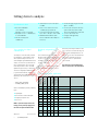
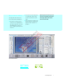
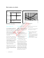
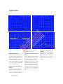
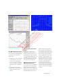
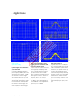
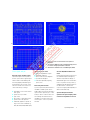
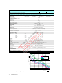
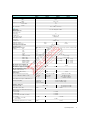
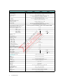
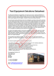
Test Equipment Solutions Datasheet
Test Equipment Solutions Ltd specialise in the second user sale, rental and distribution of
quality test & measurement (T&M) equipment. We stock all major equipment types such as
spectrum analyzers, signal generators, oscilloscopes, power meters, logic analysers etc from
all the major suppliers such as Agilent, Tektronix, Anritsu and Rohde & Schwarz.
We are focused at the professional end of the marketplace, primarily working with customers
for whom high performance, quality and service are key, whilst realising the cost savings that
second user equipment offers. As such, we fully test & refurbish equipment in our in-house,
traceable Lab. Items are supplied with manuals, accessories and typically a full no-quibble 2
year warranty. Our staff have extensive backgrounds in T&M, totalling over 150 years of
combined experience, which enables us to deliver industry-leading service and support. We
endeavour to be customer focused in every way right down to the detail, such as offering free
delivery on sales, covering the cost of warranty returns BOTH ways (plus supplying a loan
unit, if available) and supplying a free business tool with every order.
As well as the headline benefit of cost saving, second user offers shorter lead times, higher
reliability and multivendor solutions. Rental, of course, is ideal for shorter term needs and
offers fast delivery, flexibility, try-before-you-buy, zero capital expenditure, lower risk and off
balance sheet accounting. Both second user and rental improve the key business measure of
Return On Capital Employed.
We are based near Heathrow Airport in the UK from where we supply test equipment
worldwide. Our facility incorporates Sales, Support, Admin, Logistics and our own in-house
Lab.
All products supplied by Test Equipment Solutions include:
- No-quibble parts & labour warranty (we provide transport for UK mainland addresses).
- Free loan equipment during warranty repair, if available.
- Full electrical, mechanical and safety refurbishment in our in-house Lab.
- Certificate of Conformance (calibration available on request).
- Manuals and accessories required for normal operation.
- Free insured delivery to your UK mainland address (sales).
- Support from our team of seasoned Test & Measurement engineers.
- ISO9001 quality assurance.
Test equipment Solutions Ltd
Unit 8 Elder Way
Waterside Drive
Langley
Berkshire
SL3 6EP
T: +44 (0)1753 596000
F: +44 (0)1753 596001
Email: [email protected]
Web: www.TestEquipmentHQ.com
Spectrum Analyzers FSEx
20 Hz to 40 GHz
◆ Spectrum analysis with ultra-wide
dynamic range
Noise figure = 18 dB/TOI = 20 dBm
typ. (FSEB)
◆ Universal analysis of digital and
analog modulated signals (option)
such as
BPSK, QPSK, π/4-DQPSK, 8PSK,
QAM, MSK, GMSK, 2FSK, AM, FM,
PM
◆ High-speed synthesizer
5 ms for full span (FSEA, FSEB)
◆ Refresh rate, quasi-analog
25 sweeps/s
◆ Large LC TFT display
24 cm/9.5", active
◆ Future-proof modular design
Customized solutions through wide
variety of options
Characteristics
The FSE spectrum analyzers from Rohde&
Schwarz have been optimized both for
general-purpose measurements and
meeting the stringent requirements of
testing advanced digital communication
systems. High measurement speed,
future-proof modular design and excellent characteristics put the analyzers
right at the top of today's market – at an
attractive price.
◆ Combines the following functions:
spectrum analysis and analysis of digitally modulated signals (option)
◆ Spectrum analysis with maximum
dynamic range
◆ Adaptation of all models to your specific requirements by means of a wide
range of options
Frequency
Intermodulation, harmonics
Spurious
Phase noise
Time
Burst
Power ramping
Gated measurements
Modulation
Vector, frequency and phase errors
Eye and constellation diagrams
Modulation depth and deviation
Ausklappseite 1 (vorne)
Overview
WCDMA
CDMAone
PHP
GSM 900
DAB
NADC TFTS DECT
ISM WLAN
GSM 1800/1900
BLUETOOTH
SATELLITE RADAR
MICROWAVE
LINKS
FSEA 30
FSEB 30
FSEM 30
FSEK 30
20 Hz
9 kHz
1 GHz
2 GHz
3.5 GHz
7 GHz
26.5
40 GHz
((eingeklappter Zustand))
((Beschnittkante))
The spectrum analyzers
from Rohde&Schwarz
((Beschnittkante))
Modular design for a safe investment
The FSE "option building blocks"
Option/function/software
Designation
((ausgeklappter Zustand))
Ausklappseite 2 (vorne)
Frequency range up to 3.5 GHz
–
FSEA30
FSEB30 FSEM30 FSEK30
●
–
–
–
7 GHz Frequency Extension
FSE-B2
❍
●
–
–
Vector Signal Analyzer
FSE-B7
❍
❍
❍
❍
Tracking Generator 3.5 GHz
FSE-B8
❍
–
–
–
Tracking Generator 3.5 GHz with I/Q Modulator FSE-B9
❍
–
–
–
Tracking Generator 7 GHz
FSE-B10
–
❍
❍
❍
Tracking Generator 7 GHz with I/Q Modulator FSE-B11
–
❍
❍
❍
Switchable Attenuator for Tracking Generator FSE-B121)
❍
❍
❍
❍
1 dB Attenuator
FSE-B13
❍
❍
❍
❍
Controller
FSE-B15
❍
❍
❍
❍
Ethernet Interface
FSE-B16
❍
❍
❍
❍
2nd IEC/IEEE-Bus Interface
FSE-B17
❍
❍
❍
❍
❍
❍
❍
❍
1)2)
3)
Removable Hard Disk
FSE-B18
2nd Hard Disk for FSE-B18
FSE-B19
❍
❍
❍
❍
External Mixing
FSE-B21
–
–
❍
❍
Increased Level Accuracy up to 2 GHz
FSE-B22 3)
❍
❍
❍
❍
Broadband Output 741.4 MHz
FSE-B23
3)
❍
❍
❍
❍
44 GHz Frequency Extension for FSEK
FSE-B24 3)
–
–
–
❍
Noise Measurement Software
FS-K3
❍
❍
❍
❍
Phase Noise Measurement Software
FS-K4
❍
❍
❍
❍
GSM Application Firmware
FSE-K10/-K11
❍
❍
❍
❍
EDGE Application Firmware
FSE-K20/-K21
❍
❍
❍
❍
● Incorporated in basic model
1)
2)
3)
FSE-B12 and FSE-B13 cannot be fitted together.
In combination with FSE-B22 factory-fitted only.
Factory-fitted only.
❍ Can be retrofitted (option)
Getting down to analysis
◆ Resolution bandwidths
1 Hz to 10 MHz,
adjustable in steps of 1/2/3/5/10
◆ Displayed noise floor –150 dBm (typ.)
in 10 Hz bandwidth
◆ 3rd-order intercept point
+20 dBm typ.
◆ 1 dB compression point of RF input
+10 dBm
◆ Phase noise at 10 kHz from carrier:
–123 dBc (Hz) (typ.) (FSEA 30)
◆ Total level measurement uncertainty
up to 1 GHz <1 dB, up to 7 GHz 1.5 dB
◆ AM/FM audio demodulator (with
built-in loudspeaker and headphones
connector)
◆ Internal RF trigger (trigger threshold
approx. –20 dBm)
◆ 5 ms full-span sweep time with fully
synchronized sweep (FSEA, FSEB),
150 ms with FSEM, 230 ms with FSEK
◆ 1 µs zero-span sweep time
◆ Pretrigger and trigger delay
◆ Gated sweep
Vector analysis for digital
communication
Modularity safeguards investments
The analyzers of the FSE family combine
the capabilities of high-end RF or microwave spectrum analysis with those of
universal digital-signal demodulation and
analysis. This becomes possible with the
vector signal analyzer option. The spectrum analyzer function offers the wide
dynamic range necessary for many measurements on digitally modulated signals
(e.g. burst measurements), and the vector
signal analyzer option adds demodulation
capability to bit stream level for signals
such as
Series FSE analyzers are of modular
design throughout. From the wide variety
of options, you can choose exactly those
needed for your particular application
(see also fold-in page).
than what you actually need. At the same
time, you can feel sure that FSE will grow
with your tasks and requirements as virtually all options can be retrofitted. Even
extending the frequency range from
3.5 GHz to 7 GHz is no problem with
option FSE-B2.
●
❍
❍
●
❍
◆
◆
◆
◆
Eye diagram
Vector and constellation diagram
Frequency and phase error
Vector error
With a spectrum analyzer of the FSE
family, you are perfectly equipped for
the future of digital communication.
● Required
2
❍ Recommended
Spectrum Analyzers FSEx
General-purpose
RF measurements
AM and FM
sound broadcasting
TV and CATV
❍
All this is backed up by a variety of display
types:
Your decision for Spectrum Analyzer
FSE is a decision for a safe investment.
FSE options and their applications
Analog mobile
radio systems
– BPSK, QPSK, π/4-DQPSK
– 16QAM, (G)MSK, (G)FSK
You thus get an instrument tailor-made to
your requirements and pay for no more
Digital mobile
radio systems
Specifications in brief
❍
❍
FSE-B2
7 GHz Frequency Extension
FSE-B7
Vector Signal Analyzer
FSE-B8/-B9/-B10/-B11 Tracking Generator
FSE-B13
1 dB Attenuator
❍
FSE-B15
Controller
❍
FSE-B21
External Mixing
❍
FSE-B23
Broadband Output 741.4 MHz
❍
FS-K3
Noise Measurement Software
❍
FS-K4
Phase Noise Measurement
Software
❍
FSE-K10/-K11
GSM Application Firmware
❍
FSE-K20/-K21
EDGE Application Firmware
❍
❍
❍
❍
❍
❍
High speed increases efficiency
The high speed of FSE increases efficiency in development and production:
◆ FSE features a minimum full-span
sweep time of 5 ms (FSEA/B) with a
fully synchronized sweep. This means
that added speed is not at the expense of frequency accuracy but even
enhances it
◆ The shortest zero-span sweep time is
1 µs (100 ns/div) – ideal for highresolution measurements on pulse
edges
◆ Up to 25 sweeps per second is an optimal prerequisite for rapid and easy
alignments and for applications in
production
With its high measurement speed and
great ease of operation, FSE will solve
even highly complex measurement
tasks in next to no time.
Spectrum Analyzer FSEM30
Certified Quality System
ISO 9001
DQS REG. NO 1954
Spectrum Analyzers FSEx
3
The features in detail ...
FSEA 30
resolution bandwidth
1 MHz
109 dB
dynamic range
−99 dBm
displayed noise floor
of FSE at 1 MHz
resolution bandwidth
typ. −159 dBm
displayed noise floor
of FSEA 30 at 1 Hz
−174 dBm (Hz)
noise floor at
room temperature
1 MHz resolution
bandwidth (1 Hz)
60 dB
FSEA
noise figure
typ. 15 dB
–40
–50
I
169 dB
–60
TO
FSEA 30
resolution bandwidth
1 Hz
Displayed noise floor and intermodulation-free
range relative to mixer level [dB]
+10 dBm
1 dB compression
point
Dis
play
ed
–70
Dis
–80
–90
play
Dis
play
ed
–100
ed
se f
loor
loor
mo
(BW
(BW
(BW
Har
=1
=1
kHz
)
0H
=1
z)
Hz)
–120
–60
–50
–40
–30
–20
–10
0
Mixer level [dBm]
Dynamic range, noise, 3rd-order intercept point
FSE is outstanding for its extremely low
noise floor without any impairment to the
dynamic range at large signal levels. This
can be seen, for example, from the 1 dB
compression point of +10 dBm, which
yields the best dynamic range available
even at a resolution bandwidth of 1 MHz,
allowing GSM and DECT power ramps to
be determined.
FSEM/K 30 open up the microwave range
through to 26.5 GHz/40 GHz and retain
the excellent characteristics of the basic
models:
Spectrum Analyzers FSEx
se f
noi
From AF to microwave
4
loor
noi
Tops in dynamic range
Taking as a figure of merit of an analyzer
the difference between its 3rd-order
intercept point and its noise figure, FSEA
has a value of around 0 dB. Put this figure
to the test.
se f
–110
–70
Dynamic range, noise and 1 dB compression point of Spectrum Analyzer
FSEA30 at different resolution bandwidth
An extremely wide intermodulation-free
dynamic range of 115 dB is obtained due
to the low noise figure and the high 3rdorder intercept point. This not only yields
reliable intermodulation measurements
on highly linear amplifiers, but also
ensures a sufficient dynamic range for
adjacent-channel power measurements
on digitally modulated signals.
noi
ion
ess
ppr
su
nics
◆ Continuous full-span sweep
◆ Fundamental mixing (low noise floor)
as well as wide dynamic range up to
26.5 GHz
◆ Fully synchronized sweep with high
frequency accuracy even for
Full span (26.5 GHz/40 GHz)
◆ RF input adapters for N or PC 3.5 mm,
or K connector (FSEM or FSEK)
Option FSE-B21 allows the frequency
range of FSEM and FSEK to be extended
by means of external mixers. Mixers
FS-Z60 (40 GHz to 60 GHz), FS-Z75 (50 GHz
to 75 GHz), FS-Z90 (60 GHz to 90 GHz) and
FS-Z110 (75 GHz to 110 GHz) are available
as extras. Continuous automatic signal
identification, which is used to suppress
unwanted image frequency bands and
mixture products, ensures fast and easy
measurements. Due to the built-in
diplexer, two-port as well as three-port
mixers can be used.
The external mixer measurement function
features great ease of operation:
◆ Definition of frequency range and
harmonics by selecting a waveguide band
◆ Definition of all important parameters
for each waveguide band separately
◆ Frequency-dependent consideration
of mixer conversion loss
◆ Storage of parameters on hard disk
Unattained measuring
convenience
FSE makes measuring easy for you
through a large number of convenient
test functions:
◆ 4 markers, 4 delta markers
◆ Marker functions for direct measurement of
– phase noise and noise power
density
– NEXT MIN/PEAK, NEXT MIN/PEAK
RIGHT, NEXT MIN/PEAK LEFT
– bandwidths and shape factor
◆ Measurement of channel power, adjacent channel power and occupied
bandwidth
◆ Frequency counter with selectable
resolution
◆ LOW NOISE, NORMAL and LOW
DISTORTION modes for low-intermodulation and low-noise operation
◆ Hardcopy at a keystroke
◆ Simultaneous measurement of four
active traces
◆ Level, frequency and user-definable
limit lines as evaluation help with
pass/fail information
◆ Split screen with independent measurement windows
Frequency accuracy –
to the point
Tuning on FSE is absolutely synchronous
to the reference frequency for each span
including full span. This means that every
point on the frequency axis is determined
with the accuracy of the internal reference frequency and the pixel resolution.
Thus, when reducing the span for
detailed signal analysis, the tiresome
readjustment of the center frequency is
no longer needed.
FSE in its basic configuration includes an
AM/FM audio demodulator. Unknown
signals can easily be identified via headphones or the built-in loudspeaker. Modulation measurements are possible using
the optional Vector Signal Analyzer FSEB7.
Limit lines facilitate checking whether
results are within predefined tolerances.
Virtually any number of limit lines can be
defined with high accuracy by means of
50 points to meet even the most exacting
requirements.
Scalar network analysis
The optional tracking generators (see
data sheet for FSE-B8/9/10/11
PD 0757.3434) are an ideal tool for determining frequency response, attenuation
or VSWR and feature the following characteristics:
◆ Wide dynamic range for attenuation
measurements (up to 120 dB)
◆ Frequency range from 9 kHz to
3.5/7 GHz
◆ Frequency offset up to ± 200 MHz for
measurements on frequency-converting modules
The tracking generators with built-in I/Q
modulator are ideal for generating digitally
modulated signals. An external two-channel Arbitrary Waveform Generator (e.g.
AMIQ from Rohde&Schwarz) serves as
modulation source.
By adding the optional Vector Signal Analyzer FSE-B7, FSE can be expanded to a
test assembly enabling direct measurement of the influence of amplifiers or filters on phase error for instance.
Operation – as you like it
Despite their comprehensive functionalities the analyzers feature great ease of
operation. Basic functions and frequently
used help tools such as markers can be
called at a keystroke. The full operating
convenience based on a wide variety of
evaluation routines and marker functions
can be accessed via the menus.
All essential parameters and results can
be seen at a glance. All test data, scale
factors and setting parameters are logically arranged and therefore easy to find.
Setups, traces and graticules displayed in
colour make for error-free analysis of
complex results.
All models are equipped with a large
24 cm (9.5") TFT colour display with VGA
resolution (640 x 480 pixels).
The USER key allows the FSE operation to
be tailored to your specific requirements.
With this key, you can compile the functions mainly needed for your measurement tasks, which does away with frequent menu changes and speeds up measurements on the whole.
Test results –
perfectly documented
FSE affords uncomplicated logging of
results. It supports a wide variety of printers such as:
◆ Printer with HP-PCL4 and HP-PCL5
◆ HP Deskjet/HP Laserjet
◆ Postscript
Print files cannot only be output via an
interface but can also be stored on diskette or the internal hard disk. With PCX,
WMF and HP-GL (without option
Spectrum Analyzers FSEx
5
... The features in detail
Designation
Noise
Measurement
Software
Phase Noise
Measurement
Software
Application
Firmware1)
Application
Firmware2)
1)
2)
Type
Use
Functions
FS-K3
Noise figure
measurements
- Measurement of noise figure and temperature to Y-factor method
- Measurements on frequency-converting devices
- Frequency range same as basic unit, starting from 100 kHz
- Editor for ENR tables
- Runs on the internal controller (option) or on an external PC (WindowsNT/Windows98)
FS-K4
Phase noise figure
measurements
- Easy-to-use phase noise measurements
- Measurement of residual FM and PM
- Logarithmic plot over 8 decades
- Runs on the internal controller (option) or on an external PC (WindowsNT/Windows98)
FSE-K10, Mobile
FSE-K11, BTS
- Power ramp and power template
Mobile radio transmit- Spectrum due to modulation/switching
ter measurements to
- Spurious emissions
GSM standards 11.10
- Mean carrier power
and 11.20
- Phase/frequency error (with option FSE-B7)
FSE-K20, Mobile
FSE-K21, BTS
EDGE capability
added to Application
Firmware FSE-K10 and
FSE-K11
See data sheet FSE-K10/-K11.
See data sheet FSE-K20/-K21.
FSE-B15) as well as BMP and WMF (with
option FSE-B15) print formats being available, there is no problem in further
processing print files in standard text
processing systems. Using Controller
FSE-B15, it is particularly easy to generate test reports and integrate the results.
Texts can then be processed under Windows on FSE itself.
FSE as a controller
The optional Controller FSE-B15 provides
a further VGA card, a memory extension
to 64 Mbyte, a serial mouse and a keyboard. With this option, WindowsNT
applications, e.g. statistics programs or
spreadsheet analysis, can be installed on
FSE. FSE can even be linked to a network
using the optional Ethernet Interface
FSE-B16.
6
- Modulation accuracy measurement including
EVM measurement using weighting filter to ETSI
95:th-percentile measurement
measurement of origin offset suppression
- Limit lines for EDGE to ETSI05.05
Spectrum Analyzers FSEx
Complete setups, traces, limit lines and
macros can be stored on the internal hard
disk or on a diskette using the built-in
1.44 Mbyte drive.
Low overall costs
FSE in automatic test systems
◆
◆
◆
◆
◆
FSE is ideal for use in automatic test systems, affording not only fast processing
of results but also an IEC/IEEE-bus command set conforming to SCPI.
Moreover, with optional Controller
FSE-B15 and a second IEC/IEEE-bus card
(option FSE-B17), FSE can be used as a
controller for test systems, thus eliminating the need for further units and saving
space in the system cabinet.
In designing FSE, special emphasis was
placed on keeping after-sales costs to a
minimum:
Temperature-controlled fans
Calibration interval up to 2 years
Built-in calibration routines
Numerous selftest routines
Modular design
Calibration routines
Built-in calibration routines ensure that
FSE remains within defined tolerances
and thus maintains its accuracy of measurement. The routines are not performed
automatically by the instrument but can
be started by the user, thus avoiding
ongoing measurements to be interrupted.
The results of calibration routines are output by FSE in the form of comprehensive
correction tables. Comparing these tables
over an extended period of time, the user
can detect changes early and take corrective steps in time. This enhances confidence in the unit’s reliability and measurement accuracy.
A particular asset in system applications
is the internally selectable, high-precision
level calibration source, which reduces
the number of cables required.
Selftest –
the built-in diagnostic system
Modular design –
easy retrofitting of options
The instrument selftest rapidly locates
any faults down to module level. Defective modules can be replaced nearly without adjustments or extra test equipment
being required. This in conjunction with
the quick spare parts service from
Rohde&Schwarz reduces any repair or
downtime costs that might arise. The low
operating costs go easy on your budget.
The modular concept of the most important options such as Vector Signal Analyzer and 7 GHz Frequency Extension, as
well as the alignment-free incorporation
of the remaining options make it possible
to retrofit the instrument with a minimum
of downtime or installation costs being
involved.
Quality management at
Rohde&Schwarz
Lasting customer satisfaction is our primary objective. The quality management
system of Rohde&Schwarz meets the
requirements of ISO9001 and encompasses largely all fields of activity of the
company.
Rear view of FSE
Spectrum Analyzers FSEx
7
Applications ...
1
3
2
4
General-purpose RF measurements
harmonic can be displayed simultaneously with high resolution.
Two-tone measurements (1)
FSE facilitates intermodulation measurements with its wide intermodulation-free
dynamic range, which reduces measurement errors. This feature is enhanced by
the LOW DISTORTION mode, which
ensures optimum RF attenuation. Evaluation of results is rapid and easy by means
of markers and delta markers.
Low noise floor even in the microwave
range (3)
Thanks to fundamental mixing FSEM features the same constantly low noise floor
as an RF analyzer up to 26.5 GHz. As a
consequence, FSEM offers not only a
wide dynamic range, but also a considerably increased speed for measuring small
signals in the microwave range: Larger
resolution bandwidths and high sensitivity reduce sweep time while maintaining
the S/N ratio. This is of great advantage
when measuring spurious and harmonics
alike.
Harmonics measurements with split
screen (2)
The split-screen function has been provided for the convenient analysis of
results. In harmonics measurements, for
example, the fundamental and the first
8
Spectrum Analyzers FSEx
FSE phase noise as a function of carrier
spacing (4)
With a phase noise of –123 dBc (Hz) at
10 kHz from the carrier, the synthesizer
incorporated in FSEA 30 is ideal for measuring the phase noise of oscillators or
the adjacent-channel power of radio
equipment.
5
7
6
Noise figure measurements
Noise Measurement Software FS-K3 (5)
FS-K3 turns your FSE into a noise measurement system offering the advantages
of an analyzer (see also data sheet
PD 0757.2380):
◆ Wide variety of resolution bandwidths
for every application, even for measurements on narrowband DUTs
◆ If results are doubtful, the analyzer allows the test setup to be checked for
radiated interference or nonharmonics
◆ Lower frequency limit of 100 kHz
◆ Measurements on frequency-converting DUTs supported by external
generator
Phase Noise Measurement Software
FS-K4 (6)
With FS-K4 (see also data sheet
PD 0757.4201), FSE can be used as a
phase noise analyzer. The phase noise of
an input signal can easily be measured
over several decades and displayed on a
logarithmic frequency axis. The residual
FM or PM can be determined conveniently within freely selectable limits.
RMS detector: power measurement
without correction factors (7)
In the example, the power of a CDMA signal in the transmission channel and the
adjacent channels is measured. The two
traces show the influence of the DUT on
the adjacent-channel power. Measuring
power and adjacent-channel power of
digitally modulated signals requires a
spectrum analyzer to be equipped with
special detectors and test routines. FSE is
the first spectrum analyzer that features a
real power detector with wide dynamic
range – the RMS detector. Like a thermocouple power meter, this detector guarantees stable and accurate test results
without any correction factors. Considerably higher test throughput is achieved
than with the usual sample detector.
Using the available default settings for
ACP measurements in line with common
standards (NADC, PDC, CDMA, WCDMA,
etc) precise test results are obtained easily and fast.
Spectrum Analyzers FSEx
9
... Applications
8
10
9
11
Mobile radio –
digital and analog
RF power trigger replaces external trigger (no illustration)
An internal broadband level detector
(center frequency ±50 MHz) with a fixed
switching threshold of approx. –20 dBm
at the first mixer is used as a trigger
source. With this detector it is possible,
for example, to perform "spectrum due to
switching" and "spectrum due to modulation" measurements to GSM specifications without an external trigger. The
detector replaces the external trigger
needed in the gated sweep mode.
10
Spectrum Analyzers FSEx
Gap sweep: simultaneous measurement of pulse rise and fall times with
high time resolution (8 and 9)
The fast sweep time of 100 ns/div as well
as the gap sweep and pretrigger functions of Spectrum Analyzer FSE make it
possible to measure the rise and fall
times of an RF pulse simultaneously and
with high time resolution. The center of
the pulse, which is of no interest, is
blanked. Even at a resolution bandwidth
of 1 MHz FSE offers a dynamic range of
over 80 dB thanks to the high 1 dB compression point of +10 dBm.
Gated sweep (10 and 11)
The gated sweep function is indispensable for analyzing TDMA signals used in
modern communication systems. With
this function, the spectrum of burst signals can be investigated without any
interference being caused by switching
the signals on and off. The selected gate
time determines over what interval a
pulse is to be analyzed. Selection of the
gate time is easy and convenient in the
time domain display (zero span) of the
pulse.
12
14
13
Vector signal analysis
Universal analysis of digital signals
Spectrum Analyzer FSE in conjunction
with the optional Vector Signal Analyzer
FSE-B7 is ideal for demodulating and
measuring digitally modulated signals
with frequencies up to 3.5 GHz, 7 GHz,
26.5 GHz or 40 GHz. This universal tool
offers a wide variety of settings:
◆ Demodulation of all common mobileradio signals
◆ Symbol rates up to 2 MHz
◆ Type of filter
◆ Roll-off factor or BT product of filter
◆ Synchronization bit sequences
◆ Predefined, application-specific settings for all common standards, e.g.
GSM, PCS1900, NADC, CDMA (IS95)
12
I/Q signal and phase error measurements over 50 symbols of a
GSM mobile
13
Measurement of GSM power ramps to standards with high-precision
time reference through synchronization to mid-amble
14
Measurement of modulation errors of π/4-DQPSK signals (NADC)
Versatile display of results
◆ Inphase and quadrature signals
◆ Magnitude and phase
◆ Vector and constellation diagrams
◆ Eye and trellis diagrams
◆ Sum fault: amplitude, frequency,
phase, vector
Power ramp measurements
To perform power ramp measurements to
standards on TDMA systems such as
GSM or DECT, reference must be made to
synchronization sequences (pre- or midamble) in order to establish a time reference. Making such measurements to
standard is not possible using conventional analyzers – but it is no problem
with FSE!
Accurate AM, FM and PM measurements
Featuring high-accuracy measurement of
the modulation depth and frequency
deviation coupled with the display of
demodulated signals in the time domain,
FSE not only enables testing of analog
and dual-mode radio equipment but also
the determination of the transient
response in frequency and amplitude (see
data sheet PD 0757.2167).
Spectrum Analyzer FSE and the
optional vector signal analyzer provide
universal test capabilities in one unit.
Spectrum Analyzers FSEx
11
Specifications
FSEA30
FSEB30
FSEM30
FSEK30
Specifications are guaranteed under the following conditions:
30 minutes warmup time at ambient temperature, specified environmental conditions met, calibration cycle adhered to, and total calibration performed.
Data without tolerances: typical values only. Data designated "nominal" apply to design parameters and are not tested.
Frequency
Frequency range
Frequency resolution
Internal reference frequency, nominal
Aging per day1)
Aging per year1)
Temperature drift (0°C to +50°C)
Total error limit (per year)
External reference frequency
Frequency display
Resolution
Error limit (sweep time >3 × auto sweep time)
Frequency counter
Resolution
Count accuracy (S/N >25 dB)
Display range for frequency axis
Resolution/error limit of display range
Spectral purity (dBc (Hz))
SSB phase noise, f ≤500 MHz
Carrier offset
100 Hz
1 kHz
10 kHz
100 kHz2)
1 MHz 2)
Sweep time
Span = 0 Hz
Span ≥10 Hz
Error limit
Picture refresh rate (span ≤7 GHz)
Sampling rate
Number of pixels
Time measurement
Resolution
Sweep trigger
Zero span
Resolution bandwidths
3 dB bandwidths (in 1/2/3/5 steps)
FFT filter (in 1/2/3/5 steps) (see also page 16)
20 Hz to 3.5 GHz
20 Hz to 7 GHz
20 Hz to 26.5 GHz
0.01 Hz
20 Hz to 40 GHz
1x10⁻⁹
2 x10⁻⁷
5 x10⁻⁸
2.5 x10⁻⁷
10 MHz or n × 1 MHz, n = 1 to 16
with marker
0.1 Hz to 10 kHz (as a function of span)
±(marker frequency × reference error + 0.5 % × span + 10 % × resolution bandwidth + 1/2 (last digit))
measures the marker frequency
0.1 Hz to 10 kHz (selectable)
±(frequency × reference error + 1/2 (last digit))
0 Hz, 10 Hz to full span
0.1 Hz/1%
for f >500 MHz see diagram below
<–87
<–107
<–120
<–119
<–138
<–81
<–100
<–114
<–113
<–132
1 µs to 2500 s in 5% steps
5 ms to 16 000 s in steps ≤10%
<1%
>20 updates/s with 1 trace, >15 updates/s with 2 traces
50 ns (20 MHz A/D converter)
500
with marker and cursor lines
50 ns
free run, single, line, video, gated, delayed, external
additionally pretrigger, posttrigger, trigger delay
1 Hz to 10 MHz
1 Hz to 1 kHz
–60
dBc (Hz)
–70
FSEA 500 MHz
FSEA 3.5 GHz
FSEB/M/K 500 MHz
FSEB/M/K 3.5 GHz
FSEM/K 26 GHz
FSEK 40 GHz
–80
SSB phase noise
–90
–100
–110
–120
–130
–140
–150
–155
100 Hz
SSB phase noise (typical values)
12
Spectrum Analyzers FSEx
1 kHz
10 kHz
100 kHz
1 MHz
Carrier offset
10 MHz
Specifications
FSEA30
FSEB30
≤3 MHz
5 MHz
10 MHz
Shape factor 60:3 dB <1 kHz
1 kHz to 2 MHz
>2 MHz
Video bandwidths
Bandwidth error
FSEM30
<10%
<15%
+25%, –10%
<6
<12
<7
1 Hz to 10 MHz, 1/2/3/5 steps
FSEK30
Level
Display range
Maximum input level
RF attenuation 0 dB
DC voltage
CW RF power
Pulse spectral density
RF attenuation ≥10 dB
DC voltage
CW RF power
Max. pulse voltage
Max. pulse energy (10 µs)
1 dB compression of input mixer
(0 dB RF attenuation)
Displayed average noise floor
Frequency
20 Hz
1 kHz
10 kHz
100 kHz
1 MHz
10 MHz to 3.5/6 GHz
6 GHz to 7 GHz
7 GHz to 18 GHz
18 GHz to 26.5 GHz
26.5 GHz to 30 GHz
30 GHz to 40 GHz
Max. dynamic range, bandwidth 1 Hz
Displayed noise floor to 1 dB compression
Max. harmonics suppression, f >50 MHz
Max. intermodulation-free range
50 MHz to 3.5 GHz (nominal)
150 MHz to 7/26.5 GHz (nominal)
Intermodulation
TOI, intermodulation-free dynamic range,
level 2 × −30 dBm, ∆f >5 × RBW or >10 kHz
Intermodulation-free range at –40 dBm mixer level
Intercept point k2 (dBm)
noise floor displayed to 30 dBm
0V
20 dBm (=0.1 W)
97 dBµV (MHz)
0V
30 dBm (=1W)
150 V
1mWs
+10 dBm nominal
in dBm (0 dB RF attenuation, RBW 10 Hz, VBW 1 Hz, 20 averages, trace average, span 0 Hz, termination 50 Ω)
<–80
<–74
<–110
<–104
<–125
<–119
<–135
<–129
<–145, –150 typ.
<–142, typ. –145
<–145, –150 typ.
<–142, –147 typ.
<–138, –140 typ.
–
<–139
<–135, –138 typ.
–
–
<–138, –140 typ.
<–134, –139 typ.
–
–
<–135, –138 typ.
<–131, –136 typ.
–
–
–
<–120, –125 typ.
–
–
–
<–116, –122 typ.
165 dB
162 dB
160 dB
>90 dB
115 dB
–
–
115 dB
>84 dBc for f >50 MHz
(TOI >12 dBm,
18 dBm typ. )
>90 dBc for f >150 MHz
(TOI >15 dBm,
20 dBm typ. )
>25, >40 typ. for
f <50 MHz, >45,
>50 typ. for f >50 MHz
Immunity to interference
Image frequency (dB)
Intermediate frequency (dB)
Spurious response (f >1 MHz, without input signal,
0 dB attenuation)
Span <30 MHz
Span ≥30 MHz
fin = 25.06 MHz, 25.175 MHz, 5.7172 GHz
fin = 60 MHz
fin = 14.1894 GHz, 15.6722 GHz
Span >10 MHz
Other interfering signals (mixer level <–10 dBm)
50 V
0.5 mWs
–
112 dB
>94 dBc for f >100 MHz
>80 dBc for f >7 GHz,
(TOI >17 dBm, 22 dBm typ.;
>10 dBm for f >7 GHz)
105 dB
>25 for f <150 MHz, >35 typ.,
>40 for f >150 MHz, >45 typ.
>80, >90 typ.
>80, >90 typ. for f <22 GHz
>75, >80 typ. for f >22 GHz
>75 dB
>100 dB
<–110 dBm
<–100 dBm
<–100 dBm
<–110 dBm
<–100 dBm
−90 dBm
<–80 dB3)
<–75 dB 3)
Spectrum Analyzers FSEx
13
Specifications
FSEA30
Level display
Measurement display
Logarithmic level range
Linear level range
Traces
Trace detector
Trace functions
Setting range of reference level
Logarithmic level display
Linear level range
Units of level axis
Level measurement uncertainty (–40 dBm, RF attenuation 20 dB, reference level –15 dB, RBW 5 kHz)
Absolute error limit at 120 MHz
Frequency response (10 dB RF attenuation)
<1 GHz
1 GHz to 3.5/7 GHz
7 GHz to 18 GHz
18 GHz to 26.5 GHz
26.5 GHz to 40 GHz
Attenuator error limit
IF gain error
Display nonlinearity
Logarithmic level display
(RBW ≥1 kHz, analog)
0 dB to –50 dB
–50 dB to –70 dB
–70 dB to –80 dB
–70 dB to –95 dB
Linear level display
Bandwidth switching error
1 Hz to 30 kHz/100 to 500 kHz
1 MHz to 10 MHz
Total measurement uncertainty (0 dB to 50 dB below
reference level, span/RBW <100, rss 95% reliability)
<1 GHz
1 GHz to 3.5/7 GHz
7 GHz to 18 GHz
18 GHz to 26.5 GHz
26.5 GHz to 40 GHz
Pulse amplitude error (single pulses)
Bandwidth <1 MHz/≥1 MHz
FSEB30
FSEM30
FSEK30
500 × 400 pixels (with one diagram displayed); max. 2 diagrams with independent settings
10 dB to 200 dB, in steps of 10 dB
10% of reference level per division (10 divisions) or logarithmic scaling
max. 4 per diagram (max. 2 if 2 diagrams are displayed)
quasi-analog display of all results
max peak, min peak, auto peak (normal), sample, rms, average
clear/write, max hold, min hold, average
–130 dBm to 30 dBm, in steps of 0.1 dB
7.0 nV to 7.07 V in steps of 1%
dBm, dBµV, dBmV, dBµA, dBpW (logarithmic and linear level display);
mV, µV, mA, µA, pW, nW (linear level display)
The values are guaranteed for bandwidths from 10 Hz to 30 kHz and 100 kHz to 10 MHz.
<0.3 dB
<0.5 dB
<1 dB
–
–
–
–
<0.3 dB
<0.2 dB (0.1 dB typ.)
<2 dB4)
<2.5 dB4)
<3 dB4)
<0.3 dB
<0.5 dB
–
<1 dB
5% of reference level
<0.2 dB
<0.3 dB
<1 dB
<1.5 dB
–
–
–
–
<2.5 dB4)
<3 dB4)
<3.5 dB4)
<0.5 dB, nominal/<2 dB, nominal
Trigger functions
Trigger
Delayed sweep
Trigger source
Delay time
Error of delay time
Delayed sweep time
Gated sweep
Trigger source
Gate delay
Gate length
Error of gate length
Gap sweep (span = 0 Hz)
Trigger source
Pretrigger
Trigger to gap time
Gap length
14
Spectrum Analyzers FSEx
free run, line, video, RF, external
free run, line, video, RF, external
100 ns to 10 s, resolution 1 µs min. or 1% of delay time
±(1 µs + (0.1% x delay time))
2 µs to 1000 s
external, RF level
1 µs to 100 s
1 µs to 100 s, resolution min. 1 µs or 1% of gate length
±(1 µs + (0.05% × gate length))
free run, line, video, RF, external
1 µs to 100 s, 50 ns resolution, dependent on sweep time
1 µs to 100 s, 50 ns resolution, dependent on sweep time
1 µs to 100 s, 50 ns resolution
Specifications
FSEA30
FSEB30
FSEM30
FSEK30
Audio demodulation
AF demodulation types
Audio output
Marker stop time
AM and FM
loudspeaker and headphones output
100 ms to 60 s
Inputs and outputs (front panel)
RF input
VSWR (RF attenuation ≥10 dB)
f <3.5 GHz
f <7 GHz
–
f <26.5 GHz
f <37 GHz
f <40 GHz
Attenuator
Probe power
Power supply and coding connector for antennas etc
(antenna code)
Supply voltages
AF output
Open-circuit voltage
N female, 50 Ω
adapter system, 50 Ω, N adapter system, 50 Ω,
male and female, 3.5 mm N male and female, K
male and female
male and female, 2.4 mm
female
<1.5
–
–
–
<2.0
<3
–
–
0 dB to 70 dB, selectable in 10 dB steps
+15 V DC, –12.6 V DC and ground, max. 150 mA
12-contact Tuchel
<2.5
<2.5
2.5 typ.
±10 V, max. 100 mA, ground
Zout = 10 Ω , jack plug
adjustable up to 1.5 V
Inputs and outputs (rear panel)
IF 21.4 MHz
Level
Video output
Voltage (resolution bandwidth ≥1 kHz)
Reference frequency
Output, usable as input
Output frequency
Level
Input
Required level
Sweep output
Power supply connector for noise source
External trigger/gate input
Voltage
IEC/IEEE-bus control
Connector
Interface functions
Serial interface
Mouse interface
Plotter5)
Printer interface
Keyboard connector
User interface
Connector for external monitor (VGA)
Zout = 50 Ω , BNC female, bandwidth >1 kHz or resolution bandwidth
0 dBm at reference level, mixer level > –60 dBm
Zout = 50 Ω , BNC female
0 V to 1 V, full scale (open-circuit voltage); logarithmic scaling
BNC female
10 MHz
10 dBm nominal
1 MHz to 16 MHz, integer MHz
>0 dBm into 50 Ω
BNC female, 0 V to 10 V in sweep range
BNC female, 0 V and 28 V, selectable
BNC female, >10 kΩ
–5 V to +5 V, adjustable
interface to IEC625-2 (IEEE 488.2), command set: SCPI 1994.0
24-contact Amphenol female
SH1, AH1, T6, L4, SR1, RL1, PP1, DC1, DT1, C11
RS-232-C (COM 1 and COM 2), 9-contact female connectors
PS/2 mouse compatible
via IEC/IEEE bus or RS-232-C; plotter language: HP-GL
parallel (Centronics compatible) or serial (RS-232-C)
5-contact DIN female for MF-2 keyboard
25-contact Cannon female
15-contact female
General data
Display
Resolution
Pixel failure rate
Mass memory
Operating temperature range
Nominal temperature range
Limit temperature range
Storage temperature range
Humidity
Mechanical resistance
Vibration, sinusoidal
Vibration, random
24 cm LC TFT colour display (9.5")
640 × 480 pixels (VGA resolution)
<2 x 10⁻⁵
1.44 Mbyte 3 ½" diskette drive, hard disk
+5°C to +40°C
0°C to +50°C
–40°C to +70°C
+40°C at 95 % relative humidity (IEC68-2-3)
5 Hz to 150 Hz, max. 2 g at 55 Hz; 55 Hz to 150 Hz, 0.5 g const.
to IEC68-2-6, IEC68-2-3, IEC1010-1, MIL-T-28800D, class 5
10 Hz to 300 Hz, acceleration 1.2 g (rms)
Spectrum Analyzers FSEx
15
Specifications
FSEA30
Shock
Recommended calibration interval
RFI suppression
Power supply
AC supply
Power consumption
Safety
Test mark
Dimensions in mm (W x H x D)
Weight in kg
1)
2)
3)
4)
5)
FSEB30
FSEM30
FSEK30
40 g shock spectrum, to MIL-STD-810 D and MIL-T-28800 D, classes 3 and 5
1 year (2 years for operation with external reference)
to EMC directive of EU (89/336/EEC) and German EMC legislation
200 V to 240 V: 50 Hz to 60 Hz, 100 V to 120 V: 50 Hz to 400 Hz, class of protection I to VDE 411
180 VA
195 VA
230 VA
230 VA
to EN61010-1, UL3111-1, CSA C22.2 No. 1010-1, IEC1010-1
VDE, GS, UL, cUL
435 x 236 x 460 (5 HU)
435 x 236 x 570
435 x 236 x 570
22.7
23.2
25.2
25.8
After 30 days of operation.
Valid for span >100 kHz.
For models with option FSE-B23: <–50 dBm.
For frequencies >7 GHz: error after calling peaking function. For sweep times <10 ms/GHz: additional error 1.5 dB.
The plot function is not available if option FSE-B15 is installed.
Specifications
External Mixing FSE-B21
FFT filter
High frequency resolution due to very small shape factor of 2.5
Extremely short measurement time, up to 150 times faster than with conventional
filters
Resolution bandwidths (RBW)
3 dB bandwidth
in 1/2/3/5 steps
Bandwidth error
Shape factor 60:3 dB
1 Hz to 1 kHz
2%, nominal
2.5, nominal
LO output/IF input (front panel)
LO signal
Amplitude
IF signal
Full-scale level
IF input (front panel)
IF signal
Full-scale level
Level measurement error at IF inputs
(IF level –30 dBm,
reference level –20 dBm, RBW 30 kHz)
SMA female, 50 Ω
7.5 GHz to 15.2 GHz
+15.5 dBm ±3 dB
741.4 MHz
–20 dBm
SMA female, 50 Ω
741.4 MHz
–20 dBm
<1 dB
Increased Level Accuracy FSE-B22
Display range for frequency axis
Min. span
Max. span
25 x RBW
100000 x RBW, max. 2 MHz
Sweep time for 10 kHz Span
100 000
Specifications are valid for:
Temperature range
Frequency range
Resolution bandwidths
Signal level
Stop frequency
Sweep time
FFT filter
10 000
1000
Analog filter
100
Sweep time in s
≤0.5 dB with 10 dB RF attenuation
≤0.6 dB with 20/30/40 dB RF attenuation
Total level error
10
1
0,1
-/+20°C to +30°C
10 MHz to 2 GHz
5 kHz to 30 kHz/300 kHz/1 MHz
10 dB to 50 dB below reference level
≤2 GHz
≥3 x auto sweep time
0,01
1
3
10
30
100
300
RBW in Hz
Level measurement error
Additional total level error,
referred to RBW 5 kHz
<1 dB
Max. display range
100 dB
Immunity to interference
Spurious response
≤100 dBm
FSE-B23 reduces the suppression of other interference signals to –50 dBm and
must not be combined with FSE-K10/-K11.
Gain from RF input to
IF output (dB)
3 dB BW (MHz)
1 dB Attenuator FSE-B13
Frequency range
Setting range of RF attenuation
Step width
Additional attenuator uncertainty
Broadband Output 741.4 MHz FSE-B23
max. 7 GHz (stop frequency ≤7 GHz)
0 dB to 70 dB
1 dB
<0.1 dB
1)
2)
3)
FSEA
FSEB
FSEM
FSEK
6
6
4
4
60
150
1501)
40 to 802)
1501)
40 to 1203)
f <7 GHz.
7 GHz to 26.5 GHz.
7 GHz to 40 GHz.
Spectrum Analyzers FSEx
16
Connector
Impedance
BNC
50 Ω
For maximum bandwidth set instrument to 10 MHz RBW. The output level is a
function of the mixer level, which equals the input signal level minus the set RF
attenuation.
The typical loss between mixer level and IF output is 2 dB for FSEM/K, and 0 dB
for FSEA/B.
44 GHz Frequency Extension for FSEK FSE-B24
Frequency range
20 Hz to 44 GHz
Level
Displayed average noise level (DANL)
(0 dB RF attenuation, RBW = 10 Hz, VBW = 1 Hz, 20 averages, trace average,
span 0 Hz, 50 Ω termination)
40 GHz to 42 GHz
<–112, –128 dBm typ.
42 GHz to 43 GHz
<–108, –113 dBm typ.
43 GHz to 44 GHz
<–105, –110 dBm typ.
Intermodulation
3rd-order intercept point (TOI) ∆ f >5 x resolution bandwidth or >10 kHz
>40 GHz
+15 dBm typ.
2nd harmonic intercept point (SHI)
>25 dBm for f <150 MHz
>40 dBm for f >150 MHz
Level measurement error
Frequency response (10 dB RF attenuation)
40 GHz to 44 GHz
<4.0 dB1)2)
Total measurement error
(0 dB to 50 dB below reference level)
40 GHz to 44 GHz
<4.5 dB1)2)
Inputs and outputs (front panel)
RF input
VSWR (RF attenuation >0 dB)
f >40 GHz
1)
2)
Ordering information
adapter system, 50 Ω, N male und
female, K male und female, 2.4 mm
female
<3.0:1 typ.
Error after running the preselector peaking function. For sweep <10 ms/GHz: additional error
1.5 dB.
Temperature range 20°C to 35°C.
Order designation
Type
Order No.
Removable Hard Disk
FSE-B184)
1088.6993.02
Order designation
Type
Order No.
Spectrum Analyzer 20 Hz to 3.5 GHz
FSEA30
1065.6000.35
2nd Hard Disk for FSE-B18
(firmware included)
FSE-B19
1088.7248.02
Spectrum Analyzer 20 Hz to 7 GHz
FSEB30
1066.3010.35
External Mixing
FSE-B21
1084.7243.02
Spectrum Analyzer 20 Hz to 26.5 GHz
FSEM30
1079.8500.35
Increased Level Accuracy up to 2 GHz
FSE-B224)
Spectrum Analyzer 20 Hz to 40 GHz
FSEK30
1088.3494.35
Accessories supplied
Power cable, operating manual, spare fuses;
FSEM: test-port adapter 3.5 mm female (1021.0512.00) and N female
(1021.0535.00)
FSEK: test-port adapter K female (1036.4790.00) and N female (1036.4777.00)
Options (see also fold-in page)
FSE-B23 )
1088.7348.02
44 GHz Frequency Extension for FSEK
FSE-B244)
1106.3680.02
FS-K31)
1057.3028.02
Software
Noise Measurement Software, Windows
Phase Noise Measurement Software, Windows FS-K4 )
FSE-B2
1073.5044.02
Vector Signal Analyzer
FSE-B71)
1066.4317.03
1
FSE-B8 )
1066.4469.02
3.5 GHz with I/Q modulator FSE-B91)
1066.4617.02
1
1106.3480.02
Broadband Output 741.4 MHz
1
7 GHz Frequency Extension for FSEA
Tracking Generator 3.5 GHz
4
GSM Application Firmware
Mobile station
Base station
EDGE Application Firmware Mobile station
Base station
1108.0088.02
FSE-K101)
1
1057.3092.02
FSE-K11 )
1057.3392.02
FSE-K201)
1106.4086.02
1
FSE-K21 )
1106.4186.02
FSE-Z1
1066.3862.02
5 MHz to 7000 MHz (type N)
FSE-Z3
4010.3895.00
10 kHz to 18 GHz (type N)
FSE-Z4
1084.7443.02
7 GHz
FSE-B10 )
1066.4769.02
Recommended extras
7 GHz with I/Q modulator
FSE-B111)
1066.4917.02
Service Kit
Switchable Attenuator for Tracking Generator
2)
FSE-B12
1066.5065.02
DC Block
1 dB Attenuator
FSE-B132)3) 1119.6499.02
Controller for FSE (mouse and keyboard
included)
FSE-B154)
1073.5696.06
Microwave Measurement Cable and Adapter
Set for FSEM
FSE-Z15
1046.2002.02
Ethernet Interface 15-contact AUI connector
FSE-B165)
1073.5973.02
Harmonic Mixer
FS-Z601)
1089.0799.02
FSE-B165)
1073.5973.03
50 GHz to 75 GHz
FS-Z75 )
1089.0847.02
RJ-45 connector (twisted pair) FSE-B16 )
1073.5973.04
60 GHZ to 90 GHz
FS-Z901)
1089.0899.02
FSE-B175)
1066.4017.02
1
1089.0976.00
Thin-wire BNC connector
5
2nd IEC/IEEE-Bus Interface for FSE
40 GHz to 60 GHz
75 GHZ to 110 GHz
1
FS-Z110 )
Spectrum Analyzers FSEx
17
Order No.
Order designation
Service Manual
–
1065.6016.24
High-Power Attenuators
Headphones
–
0708.9010.00
German
PSA-Z2
1007.3001.31
US
PSA-Z2
1007.3001.02
FSE-Z2
1084.7043.02
1m
PCK
0292.2013.10
2m
PCK
0292.2013.20
19" Rack Adapter, with front handles
ZZA-95
0396.4911.00
Transit Case
ZZK-954
1013.9395.00
Transit Case (FSEM30 and FSEK30 only)
ZZK-955
1013.9408.00
Matching Pads, 75 Ω L section
RAM
0358.5414.02
RAZ
0358.5714.02
Keyboard
PS/2 Mouse
IEC/IEEE-Bus Cable
Series resistor, 25 Ω
SWR Bridge
5 MHz to 3000 MHz
ZRB2
0373.9017.52
40 kHz to 4 GHz
ZRC
1039.9492.52
Order No.
RBU 100
RBU 50
1073.8820.xx
1073.8895.xx
xx: 03/06/10/
20/30
ESV-Z3
0397.7014.52
–
1021.0541.00
–
1021.0529.00
–
1036.4783.00
K male
–
1036.4802.00
2.4 mm female
FSE-Z5
1088.1627.02
–
1065.9480.00
100 W
50 W
Steps: 3/6/10/20/30 dB
For FSEM only:
Test-Port Adapter
N male
3.5 mm male
For FSEK only:
Test-Port Adapter
N male
Probe Power Connectors 3-contact
1)
2)
3)
4)
5)
Extra data sheets available.
FSE-B12 and FSE-B13 cannot be fitted together.
In combination with FSE-B22 factory-fitted only.
Cannot be retrofitted, factory-fitted only.
FSE-B16 and FSE-B17 require option FSE-B15.
PD 0757.1519.28 ⋅ Spectrum Analyzers FSEx ⋅ Trade names are trademarks of the owners ⋅ Subject to change ⋅ Data without tolerances: typical values
Accessories for current, voltage and fieldstrength measurement
see accessories for Test
Receiver and Spectrum
Analyzers, data sheet
PD 0756.4320
Type
0501 (Bi ko)
Type
Printed in Germany
Order designation
ROHDE&SCHWARZ GmbH & Co. KG ⋅ Mühldorfstraße 15 ⋅ 81671 München ⋅ Germany ⋅ P.O.B. 8014 69 ⋅ 81614 München ⋅ Germany ⋅ Telephone +49894129-0
www.rohde-schwarz.com ⋅ Customer Support: Tel. +491805124242, Fax +4989 4129-13777, E-mail: [email protected]