1
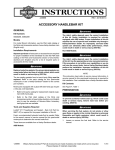
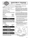
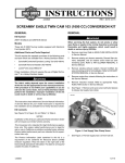
-J04210
REV. 2007-08-02
AUTOMATIC COMPRESSION RELEASE (ACR) OVERLAY WIRE
HARNESS KIT
Kit Number
If vehicle is equipped with Harley-Davidson Smart Security
System, see Owner's Manual for instructions to disarm the
system.
70623-06
1.
Position motorcycle on a suitable lift.
This harness is a component of Screamin' Eagle 110 cubic
inch (1800 cc) Engine Conversion kits. Please refer to those
kits for fitment information.
2.
Remove seat according to the instructions in the Service
Manual.
GENERAL
erman
G
.
e
.
y
n
3.
Rosto
ck
For model fitment information, please see the P&A Retail Catalog or the Parts and Accessories section of www.harleydavidson.com (English only).
Softail: Remove maxi-fuse. Refer to METRI-PACK 800 in
Service Manual.
Dyna: Remove electrical caddy cover and maxi-fuse. Refer
to FUSES in Service Manual.
Tools and Supplies Required
This kit requires Terminal Pick Tool (Snap On GA500A), pair
of formed terminal picks, or suitable tool.
•
It is recommended that the calibration update be done
before the installation of this kit to eliminate the possibility of ACR failure.
w
w
w.
When servicing the fuel system, do not smoke or allow
open flame or sparks in the vicinity. Gasoline is extremely
flammable and highly explosive, which could result in
death or serious injury. (00330a)
4.
Remove fuel tank according to the instructions in the
Service Manual.
Removing Terminal Wires from Fuse Blocks
sh
Installation of this kit requires a calibration update using
Digital Technician. Failure to download calibration update
before starting motorcycle will result in ACR failure.
(00567b)
Touring: Remove left side saddlebag, left side cover, and
maxi-fuse. Refer to SADDLEBAG REMOVAL in Service
Manual.
o p. d e
Models
NOTE
e
See Figure 1. It is necessary to depress both terminal retention
tangs at the same time to allow extraction.
h d o nli
The rider's safety depends upon the correct installation
of this kit. Use the appropriate service manual procedures.
If the procedure is not within your capabilities or you do
not have the correct tools, have a Harley-Davidson dealer
perform the installation. Improper installation of this kit
could result in death or serious injury. (00333a)
is03687
n
NOTE
This instruction sheet references Service Manual information.
A Service Manual for your model motorcycle is required for
this installation and is available from a Harley-Davidson dealer.
Kit Contents
See Figure 27 and Table 1.
REMOVAL
Prepare for Service
Figure 1. Depress Terminal Retention Tangs
NOTES
Complete these steps if this is a replacement to an existing
ACR Overlay Wire Harness Kit. Otherwise, proceed with the
INSTALLATION section for the appropriate model.
-J04210
1.
To ensure terminal retention tangs can be depressed,
identify the appropriate terminal wire and push into cavity
on back side of fuse block.
1 of 10
NOTES
Terminal Pick (Snap On GA500A) is normally used to remove
the terminal wires from fuse blocks. If there is difficulty removing
the wires with this tool, or if this tool is not available, a formed
tool or other suitable tool can be used to perform this task.
is03686
See Figure 2. A pair of Terminal Picks formed from a hacksaw
blade have the appropriate thickness and stiffness to remove
terminal wires from fuse blocks.
is03596
3
2
1
Figure 4. Pair of Formed Terminal Picks
erman
G
.
e
.
y
n
Rosto
ck
is03676
1.
2.
3.
4.
2-3/8 in. (55.56 mm)
1-1/4 in. (31.75 mm)
7/16 in. (11.11 mm)
1/16 in. (1.5875 mm)
o p. d e
4
2.
See Figure 3 to Figure 5. While maintaining pressure on
terminal wire from the back side, insert terminal pick tool
into the small slots adjacent to the fuse cavity on top side
of fuse block, simultaneously depressing tangs on both
sides of terminal.
3.
Pull terminal wire from bottom to extract terminal from fuse
block.
w
w
is03772
w.
sh
Figure 2. Formed Terminal Pick Dimensions
h d o nli
n
e
Figure 5. Terminal Slots in Fuse Block Cavity
Installing Terminal Wires into Fuse Blocks
NOTE
Terminal wire must be fully seated or fused circuit may become
intermittent or inoperative.
1.
Push terminal wire into desired cavity.
2.
Ensure retention tangs are seated by pulling on terminal
wire after inserting.
3.
If necessary, spread retention tangs outward with a thin
blade and reinsert terminal wire.
INSTALLATION (TOURING MODELS)
Remove Electrical Components
1.
Replacement Only: Separate ACR front and rear connectors from the ACR assemblies on the cylinder heads.
2.
Remove right side cover from frame.
Figure 3. Terminal Pick Tool (Snap On GA500A)
-J04210
2 of 10
3.
See Figure 6. Disconnect electronic control module (ECM)
connector from ECM module (2).
4.
See Figure 7. Using screwdriver, remove clear plastic
secondary lock from ECM connector.
5.
Disassemble ECM harness connector and remove plug
from cavity 15. Refer to PACKARD ELECTRICAL CONNECTORS, DISASSEMBLY in Service Manual.
is03583
4
1
5
5
is03592
3
2
2
3
ECM connector
ECM module
EFI fuse block
Main wiring harness
Rosto
ck
1.
2.
3.
4.
1.
2.
3.
4.
5.
Figure 8. EFI Fuse Block (Stock)
Figure 6. Electrical Bracket Assembly
1
2
w
w
11. See Figure 9. Release catches to remove wire trough
cover from frame backbone. To release catches, carefully
insert blade of flat tip screwdriver into slot only as far as
necessary to release catch.
is03597
sh
is03604
Fuse block, back side
Fuel pump fuse circuit
Spare fuse circuit
Cavity H (Y/GN), fuel pump fuse
Cavity M and O, spare fuse
o p. d e
1
rma
e
G
.
ny
e 4
.
n
w.
h d o nli
1. Secondary lock
2. Latch (2)
n
e
Figure 9. Release Catches From Cover
Figure 7. Remove Secondary Lock
6.
See Figure 6. Remove Electronic Fuel Injection (EFI) fuse
block (3) from electrical bracket assembly.
7.
See Figure 8. Remove fuel pump fuse (2) and spare fuse
(3) from EFI fuse block.
8.
Using terminal pick tool, remove fuel pump fuse (Y/GN)
terminal wire from cavity H (4).
9.
Remove and discard terminals wires from spare fuse
cavities M and O (5).
Install ACR Overlay Wire Harness
1.
See Figure 10. Install fuel pump fuse (Y/GN) terminal wire
previously removed from cavity H into spare fuse cavity
O (2).
2.
Install Y/GN terminal wires from ACR overlay wire harness
into cavities M and H (3).
3.
Install fuel pump fuse (4) and ACR fuse (5) (formally spare
fuse) into EFI fuse block.
10. Remove wire trough cover and cable straps to gain access
to main wiring harness. Refer to WIRE TROUGH in Service Manual.
-J04210
3 of 10
Route ACR Overlay Wire Harness
is03584
3
1
1.
Determine best routing for ACR overlay wire harness to
cylinder heads.
2.
See Figure 11. Determine which cable straps need to be
cut. Using a paint pen, draw a line on the conduit and/or
wire bundle to mark original location of stock cable straps.
3.
Cut and discard stock cable straps as necessary, starting
at top of engine, along right side of frame backbone, and
back to ECM and fuse block.
4.
Connect ACR overlay wire harness to the ACR assemblies
on the cylinder heads.
5.
See Figure 12. Reinstall cable straps provided in kit in
original locations and as otherwise necessary, ensure:
3
2
5
4
Fuse block, back side
Cavity O (Y/GN), fuel pump
Cavity H and M (Y/GN), ACR
Fuel pump fuse circuit
ACR fuse circuit
Slack is allowed at cylinder heads for relative motion.
b.
Extra wire lengths and harness are cinched up as
needed to keep from rubbing on fuel tank, oil tank,
battery box, frame, etc.
erman
G
.
e
.
y
n
6.
Install wire trough covers.
is03598
Rosto
ck
1.
2.
3.
4.
5.
a.
See Figure 6. Install EFI fuse block (3) on electrical bracket
assembly.
5.
Install V/GY pin terminal wire from ACR overlay harness
into cavity 15 of ECM harness connector.
6.
Assemble ECM harness connector and secure with cable
strap. Refer to PACKARD ELECTRICAL CONNECTORS,
ASSEMBLY in Service Manual.
7.
Reconnect electronic control module (ECM) connector (1)
to ECM module (2).
w
w
is03602
w.
Figure 11. Mark Location of Cable Straps
h d o nli
sh
4.
o p. d e
Figure 10. EFI Fuse Block (Modified)
n
e
Figure 12. Cable Straps and Wire Routing (Touring)
-J04210
4 of 10
INSTALLATION (SOFTAIL MODELS)
is03748
Remove Electrical Components
1.
Replacement Only: Separate ACR front and rear connectors from the ACR assemblies on the cylinder heads.
2.
See Figure 13. Disconnect electronic control module
(ECM) connector (1) from ECM module (2).
3.
See Figure 7. Using screwdriver, remove clear plastic
secondary lock from ECM connector.
4.
Disassemble ECM harness connector and remove plug
from cavity 15. Refer to PACKARD ELECTRICAL CONNECTORS, DISASSEMBLY in Service Manual.
4
3
2
1.
2.
3.
4.
2
erman
G
.
e
.
y
n
7.
Remove fuel pump fuse (2) and spare fuse (3) from right
hand fuse block.
8.
See Figure 15. Using terminal pick tool, remove fuel pump
fuse (Y/GN) terminal wire from cavity O (4).
9.
Remove and discard terminal wires from spare fuse cavities G and H (5).
1. ECM connector
2. ECM module
3. Main wiring harness
is03626
Figure 13. Electronic Control Module (ECM) and
Connections
5
5.
See Figure 14. Remove fuse block cover.
5
6.
See Figure 15. Remove right hand fuse/relay block to
access terminal locations.
w
w
Figure 15. Fuse Blocks
o p. d e
3
is03624
Fuel pump fuse
Spare fuse
Fuse block, right
Fuse block, left
w.
4
1
sh
1
Rosto
ck
is03623
1
h d o nli
n2
e
3
1.
2.
3.
4.
5.
Figure 14. Fuse Block Cover
Fuse block, back side
Fuel pump fuse circuit
Spare fuse circuit
Cavity O (Y/GN), fuel pump fuse
Cavity G and H, spare fuse
Figure 16. Right Fuse Block (Stock)
Install ACR Overlay Wire Harness
-J04210
1.
See Figure 17. Install fuel pump fuse (Y/GN) terminal wire
previously removed from cavity O into spare fuse cavity
H (2).
2.
Install Y/GN terminal wires from ACR overlay wire harness
into cavities O and G (3).
5 of 10
3.
Install fuel pump fuse (4) and ACR fuse (5) (formally spare
fuse) into right hand fuse block.
is03653
2.
See Figure 11. Determine which cable straps need to be
cut. Using a paint pen, draw a line on the conduit and/or
wire bundle to mark original location of stock cable straps.
3.
Cut and discard stock cable straps as necessary, starting
at top of engine, along right side of frame backbone, and
back to ECM and fuse blocks.
4.
Connect ACR overlay wire harness to the ACR assemblies
on the cylinder heads.
5.
See Figure 18. Reinstall cable straps provided in kit in
original locations and as otherwise necessary, ensure:
1
3
2
3
a.
Slack is allowed at cylinder heads for relative motion.
b.
Extra wire lengths and harness are cinched up as
needed to keep from rubbing on fuel tank, oil tank,
battery box, frame, etc.
4
is03754
5
Fuse block, back side
Cavity H (Y/GN), fuel pump fuse
Cavity O and G (Y/GN), ACR fuse
Fuel pump fuse circuit
ACR fuse circuit
Rosto
ck
1.
2.
3.
4.
5.
erman
G
.
e
.
y
n
See Figure 15. Install right fuse block to original position.
5.
Install V/GY pin terminal wire from ACR overlay harness
into cavity 15 of ECM harness connector.
6.
Assemble ECM harness connector and secure with cable
strap. Refer to PACKARD ELECTRICAL CONNECTORS,
ASSEMBLY in Service Manual.
7.
Reconnect electronic control module (ECM) connector (1)
to ECM module (2).
1.
w
w
Route ACR Overlay Wire Harness
Determine best routing for ACR overlay wire harness to
cylinder heads.
-J04210
w.
sh
4.
o p. d e
Figure 17. Right Fuse Block (Modified)
h d o nli
n
e
Figure 18. Cable Straps and Wire Routing (Softail)
6 of 10
INSTALLATION (DYNA MODELS)
is03658
Remove Electrical Components
1.
Replacement Only: Separate ACR front and rear connectors from the ACR assemblies on the cylinder heads.
2.
See Figure 19. Firmly grasp both side of electrical caddy
cover and pull outward to remove.
is03656
Figure 21. Removing Fuse Blocks
8.
See Figure 23. Remove spare fuse (2) from right fuse
block.
9.
See Figure 22. Using terminal pick tool, remove fuel pump
fuse (O/GY) terminal wire from cavity G (3) in left hand
fuse block.
See Figure 20. Disconnect electronic control module
(ECM) connector (1) from ECM module.
4.
See Figure 7. Using screwdriver, remove clear plastic
secondary lock from ECM connector.
10. See Figure 23. Remove and discard terminal wires from
spare fuse cavities L and K (3) in right hand fuse block.
is03659
Disassemble ECM harness connector and remove plug
from cavity 15. Refer to PACKARD ELECTRICAL CONNECTORS, DISASSEMBLY in Service Manual.
is03657
1
w
w.
3
1.
2.
3.
4.
3
sh
2
w
1
o p. d e
3.
Rosto
ck
See Figure 22. Remove fuel pump fuse (2) from left fuse
block.
erman
G
.
e
.
y
n
Figure 19. Electrical Caddy Cover
5.
7.
hdon
n
li
e
ECM POWER
2
FUEL PUMP
ENGINE CTL
4
ECM connector
Main wiring harness
Left fuse block
Right fuse block
1. Left fuse block, back side
2. Fuel pump fuse circuit
3. Cavity G (O/GY), fuel pump fuse
Figure 22. Left Fuse Block (Stock)
Figure 20. Electrical Caddy
6.
See Figure 21. Remove left and right fuse blocks (Figure
20, Item 3, 4) from electrical caddy.
a.
Insert small screwdriver into slot located under each
fuse block.
b.
Using screwdriver, disengage left fuse block from
electrical caddy.
c.
Repeat above step for right fuse block.
-J04210
7 of 10
is03660
is03663
1
1
3
3
3
2
2
SPARE FUSE
SPARE FUSE
4
SPARE FUSE
SPARE FUSE
ACCESSORIES ACCESSORIES
SPARE FUSE
SPARE FUSE
SPARE FUSE
SPARE FUSE
ACCESSORIES
ACCESSORIES
erman
G
.
e
.
y
n
1. Right fuse block, back side
2. Spare fuse circuit
3. Cavity L and K, spare fuse
1.
2.
3.
4.
Figure 23. Right Fuse Block (Stock)
Right fuse block, back side
Cavity L (O/GY), fuel pump
Cavity K (Y/GN), ACR
Fuel pump fuse circuit
Rosto
ck
Figure 25. Right Fuse Block (Modified)
Install ACR Overlay Wire Harness
3.
Install Y/GN terminal wires from ACR overlay wire harness
into cavity G (Figure 24, Item 2) in left fuse block and cavity
K (Figure 24, Item 3) in right fuse block.
Install fuel pump fuse (Figure 24, Item 4) into right fuse
block and ACR fuse (Figure 23, Item 3) into left fuse block.
is03662
1
w
w
ECM POWER
4.
See Figure 20. Install left and right fuse block (3, 4) in
electrical caddy.
5.
Install V/GY pin terminal wire from ACR overlay harness
into cavity 15 of ECM harness connector.
6.
Assemble ECM harness connector and secure with cable
strap. Refer to PACKARD ELECTRICAL CONNECTORS,
ASSEMBLY in Service Manual.
7.
See Figure 20. Reconnect electronic control module (ECM)
connector (1) to ECM module.
8.
See Figure 19. Install electrical caddy cover.
Route ACR Overlay Wire Harness
1.
w2.
3
FUEL PUMP
ENGINE CTL
1. Left fuse block, back side
2. Cavity G (Y/GN), ACR
3. ACR fuse circuit
o p. d e
2.
See Figure 25. Install fuel pump fuse (O/GY) terminal wire
previously removed from cavity G in left fuse block into
spare fuse cavity L (2) in right fuse block.
sh
1.
e
Determine best routing for ACR overlay wire harness to
cylinder heads.
h d o nli
n
2.
See Figure 11. Determine which cable straps need to be
cut. Using a paint pen, draw a line on the conduit and/or
wire bundle to mark original location of stock cable straps.
3.
Cut and discard stock cable straps as necessary, starting
at top of engine, along right side of frame backbone, and
back to ECM and fuse blocks.
4.
Connect ACR overlay wire harness to the ACR assemblies
on the cylinder heads.
5.
See Figure 26. Reinstall cable straps provided in kit in
original locations and as otherwise necessary, ensure:
a.
Slack is allowed at cylinder heads for relative motion.
b.
Extra wire lengths and harness are cinched up as
needed to keep from rubbing on fuel tank, oil tank,
battery box, frame, etc.
Figure 24. Left Fuse Block (Modified)
-J04210
8 of 10
is03666
1.
Install fuel tank according to the instructions in the Service
Manual.
2.
Touring: Install maxi-fuse, left side cover, and left saddlebag. Refer to SYSTEM FUSES and SADDLEBAG
INSTALLATION in Service Manual.
Softail: Install maxi-fuse. Refer to METRI-PACK 800 in
Service Manual.
Dyna: Install maxi-fuse and electrical caddy. Refer to
FUSES in Service Manual.
After installing seat, pull upward on seat to be sure it is
locked in position. While riding, a loose seat can shift
causing loss of control, which could result in death or
serious injury. (00070b)
erman
G
.
e
.
y
n
Figure 26. Cable Straps and Wire Routing (Dyna)
Installation of this kit requires a calibration update using
Digital Technician. Failure to download calibration update
before starting motorcycle will result in ACR failure.
(00567b)
•
If the calibration update has not been performed, it
needs to be done NOW. Starting the motorcycle
without the calibration update WILL cause ACR failure.
4.
Start and run engine. Repeat several times to ensure
proper operation.
FINAL ASSEMBLY
NOTE
w
w
sh
Complete Steps 1 through 4 if this is a replacement to an
existing ACR Overlay Wire Harness Kit. Otherwise, return to
original Instruction Sheet.
-J04210
Install seat according to the instructions in the Service
Manual.
o p. d e
Rosto
ck
3.
w.
h d o nli
n
e
9 of 10
SERVICE PARTS
is03622
B
A
C
1
D
B
E
Rosto
ck
3
o p. d e
erman
G
.
e
.
y
n
2
w
w
11
w.
0
h d o nli
sh
110
n
e
Figure 27. Service Parts: Automatic Compression Release (ACR) Overlay Wire Harness Kit
Table 1. Service Parts: Automatic Compression Release (ACR) Overlay Wire Harness Kit
Item
Description (Quantity)
Part Number
1
ACR overlay wire harness
Not Sold Separately
2
Automatic compression release
(ACR)
Reference Only
Item
Description (Quantity)
A
ACR front
3
Cylinder head
Reference Only
B
ACR rear
4
Strap, cable (6) (Not Shown)
10006
C
ECM cavity 15
5
Strap, cable (3) (Not Shown)
10039
D
EFI fuse block, spare fuse
6
Strap, cable (6) (Not Shown)
10065
E
EFI fuse block, fuel pump fuse
-J04210
Part Number
Electrical Connections:
10 of 10