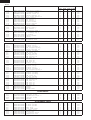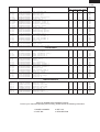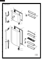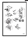
1
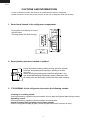
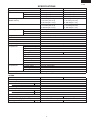
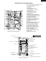
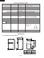
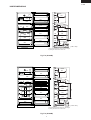
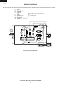
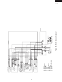
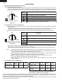
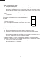
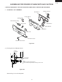
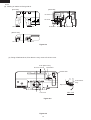
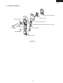
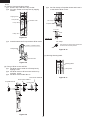
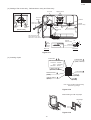
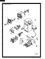
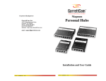
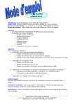
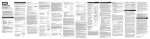
SJ-59M
SJ-69M
SERVICE MANUAL
S9334SE68DPU1
REFRIGERATOR-FREEZER
MODELS
SJ-59M-SL1/WH1
SJ-69M-SL1/WH1
In the interests of user-safety (Required by safety regulations in some
countries) the set should be restored to its original condition and only
parts identical to those specified should be used.
DESTINATION ......................... 1
Refrigerant; HFC-134a
Refer to "HFC-134a COOLING UNIT" Service Manual for handling this refrigerant.
TABLE OF CONTENTS
page
CAUTIONS AND INFORMATIONS .................................................................................................................. 2
SPECIFICATIONS ............................................................................................................................................ 3
DESIGNATION OF VARIOUS PARTS ............................................................................................................. 5
LIST OF ELECTRICAL PARTS ........................................................................................................................ 6
DIMENSIONS ................................................................................................................................................... 6
WIRING DIAGRAM ........................................................................................................................................... 8
FUNCTIONS ................................................................................................................................................... 10
ASSEMBLING PROCEDURES OF MAIN PARTS AND CAUTIONS ............................................................. 13
COOLING UNIT .............................................................................................................................................. 21
REPLACEMENT PARTS LIST ....................................................................................................................... 23
SHARP CORPORATION
1
SJ-59M
SJ-69M
CAUTIONS AND INFORMATIONS
In case of following troubles, the cause is not related with the failure of refrigerator.
Please mention the correct way to the customer for the use of refrigerator when the repairing.
1. Some foods freezed in the refrigerator compartment.
Do not place food directly in front of
cold air outlet.
This may lead to the food freezing.
cold air flow
IN
OUT
2. Some plastic parts were cracked or splitted.
Some household cleaning chemicals may affect the internal
food liner and plastic parts resulting in splitting or cracks
occurring.
When cleaning all plastic parts inside this refrigerator, only
use diluted dishwashing liquid(soapy water). Make sure that
all plastic parts are thoroughly rinsed with water after cleaning.
3. IT IS NORMAL for the refrigerator to produce the following sounds.
Cracking or crunching sound;
Sound produced by expansion and contraction of inner walls and internal parts during cooling.
Squeaking sound;
Sound produced by expansion and contraction of internal parts.
Sound of flowing fluid (gurgling sound, fizzing sound);
Sound of refrigerant flowing in pipes (sound may become louder from time to time).
2
SJ-59M
SJ-69M
SPECIFICATIONS
Items
Type
Outer dimensions
Height
Width
Depth
Rated storage volume
(Rated volume)
Gross volume
Defrosting
System
Start
Finish
Temperature control
No-frost freezer
Interior lamp
Caster
Evaporating pan
Refrigerator
R glass shelf ass'y
Compartment
V glass shelf ass'y
Vegetable case
V parting plate
R door pocket
Egg tray
Bottle pocket
Utility case pocket
Fresh case
Tube stand
Freezer
Freezer shelf ass'y
Compartment
Ice cube maker
Ice storage box
F door pocket
Deodorizing unit
SJ-59M
2-Door
1620mm(63.8")
760mm(29.9")
740mm(29.1")
492 liter (17.4 cu.ft)
F: 151 liter (5.3 cu.ft)
R: 341 liter(12.1 cu.ft)
526 liter (18.6 cu.ft)
F: 177 liter (6.3 cu.ft)
R: 349 liter(12.3 cu.ft)
Heater system
Automatic
Automatic
Automatic (Adjustable)
Yes
2
4
1
2
1
1
1
1
2
2
1
1
2
1
Twin ice cube maker
1
2
2 (Honeycomb type)
RATING
Items
SJ-59M
Rated voltage
Rated frequency
Rated current
(A)
Rated input of heating systems
(W)
Rated voltage
Rated frequency
Rated current
(A)
Rated input of heating systems
(W)
Climate class
Refrigerant (Charging quantity)[Non-flammable] HFC-134a(120g)
Insulation blowing gas [Flammable]
Net Weight
(kg)
83
3
SJ-69M
2-Door
1820mm(71.6")
760mm(29.9")
740mm(29.1")
577 liter (20.4 cu.ft)
F: 151 liter (5.3 cu.ft)
R: 426 liter(15.1 cu.ft)
606 liter (21.4 cu.ft)
F: 177 liter (6.3 cu.ft)
R: 429 liter(15.1 cu.ft)
3
2
SJ-69M
110V~
50Hz
2.9
140
110-120V~
60Hz
2.9-3.0
140-165
ST
HFC-134a(130g)
Cyclo pentane (HC)
90
SJ-59M
SJ-69M
PLUG TYPE
Plug cord
Plug type
3 pin
A-2(UL type)
Destination mark
1
COLOR
Items
Outside color
Inside color
-SL1
Silver
White
-WH1
White
4
SJ-59M
SJ-69M
DESIGNATION OF VARIOUS PARTS
The names in parenthesis" [ ]" are the denominations
used in the REPLACEMENT PARTS LIST.
1
2
19
20
3
4
5
21
1. Freezer light [Lamp]
2. Freezer fan
3. Freezer shelf [F shelf ass’y]
4. Ice cube maker
5. Ice cube box [Ice storage box]
6. Deodorizing unit
7. Freezer temp. control knob
8. Fresh case [Chilled case]
9. Refrigerator fan
10. Refrigerator temp. control knob
11. Refrigerator shelf [R glass shelf ass’y]
22
6
7
(59 type; 2 shelves, 69 type; 3 shelves)
23
6
8
9
10
11
12. Refrigerator light [Lamp]
13. Shelf [V glass shelf ass’y]
14. Vegetable crispe r[Vegetable case]
15. Separator plate [V parting plate]
16. Evaporating pan & cover
17. Casters
18. Adjustable feet [Adjustable leg ass’y]
19. Fan & light switch for freezer
20. Fan & light switch for refrigerator
21. Freezer pocket [F door pocket]
22. Water supply cup [Water cup]
23. Magnetic door seal [Door packing]
24. Utility case [Utility case pocket]
25. Egg holder [Egg tray]
26. Free pocket[R door pocket]
24
25
26
27
12
13
14
15
16
23
28
17
18
(59 type; 1 pocket, 69 type; 2 pockets)
27. Bottle pocket
28. Bottle guard [Tube stand]
Figure D-1. External Description
Upper hinge cover
Mark: Cold air flow
Freezer fan
Hot pipe
Fan motor
Freezer
compartment
Defrost thermostat
Evaporator
Freezer temp. control knob
Defrost heater
Hot pipe
Refrigerator
compartment
Timer,R-fan thermo ass’y
Refrigerator fan
Damper thermostat
Refrigerator temp. control knob
Drain pipe
Vegetable case
Evaporating pan cover
Compressor
Starting relay, Overload relay(Protector)
Evaporating pan
Sub condenser
Adjustable leg ass’y
Caster
This figure shows SJ-59M
Figure D-2. Constructions
5
SJ-59M
SJ-69M
LIST OF ELECTRICAL PARTS
ITEMS
Thermostat
TYPE NAME
MM1-8123
Defrost thermostat
Thermo. fuse
F-fan motor
R-fan motor
S101
SF70E
3R00171
3R00122B
(R-fan fuse)
Defrost heater
Door switch
Damper thermostat
Defrost timer
123
MM6-4286
DSD-5
MM1-6176
TMDFX04FB2
Lamp socket (F/R)
F-lamp
R-lamp
R-fan thermo. R-fan thermo.
ass'y
R-fan thermo.heater
Compressor
—
—
—
S101
RSS2
FGI85HAK
RATING
125V 6A
250V 3A
250V 8A
250V 10A
110-120V 60Hz
100V 50/60Hz
110V 60Hz
250V 2A
110-120V 88.2Ω
250V 0.25A
—
110-127V
50/60Hz
SPECIFICATIONS
(At normal notch)
ON/OFF : -19/-24˚C
Open/Close : 10/1˚C
Working temp. : 70˚C
Working with ø100 fan
Working with ø80 fan
Cut OFF 130˚C
150W at 115V
4 terminals push-button type
Open/Close : 2/-3˚C
Integration type
Cycle time : 12h / 10h (50/60Hz)
Delay time : 4.8m / 4.0m (50/60Hz)
E-12(Hard plastic body type)
E-12
E-12
Open/ Close : 7/15˚C
1.1W at 230V
Cooling capacity : 209kcal/h(60Hz)
Common
Main coil : 1.78 Ω
Aux. coil : 6.8 Ω
(at 25˚C)
250V 1A
130V 10W
130V 15W
250V 8A
350V, 2W, 10kΩ
115V/60Hz
Aux. coil
Starting relay
PTH7M4R7MC1
Overload relay(Protector) 4TM771RFBZZ
4.7 Ω +
– 20% (at 25˚C) 180V
Open/ Close : 130˚C / 61˚C
—
—
DIMENSIONS
OUTER DIMENSIONS AND CLEARANCE
more than
60
more than
760
1
more than
60
more than
760
60
A
1420
1480
9.5
553
90
740
520
72.5
60.5
12
B
135
1340
( Unit : mm)
A
B
SJ-59M
SJ-69M
1620
979
1820
1179
1 Include the panel/badge. Not include the handle.
Fig. E-1
6
Main coil
SJ-59M
SJ-69M
587
90
174
INNER DIMENSIONS
294
450
90
587
264
603
630
615
615
607
133
310
310
121
615
607
133
600
335
242
615
285
466
110
180
355
135
177
125
110
615
227
( Unit : mm)
The dimensions between shelves can be changed
by setting the shelves on the other rails.
90
603
450
587
90
615
110
615
110
294
264
587
174
Fig. E-2 (SJ-59M)
607
133
171
615
615
607
133
600
285
310
310
666
135
110
615
615
135
615
180
355
310
335
242
177
125
630
227
( Unit : mm)
The dimensions between shelves can be changed
by setting the shelves on the other rails.
Fig. E-3 (SJ-69M)
7
SJ-59M
SJ-69M
WIRING DIAGRAM
Be sure to replace the electrical parts with specified ones for maintaining the safety and performance of the set.
G
BR
OR
Y
R
P
B
BK
SB
G-Y
W
: GRAY
: BROWN (Live)
: ORANGE
: YELLOW
: RED
: PINK
: BLUE (Neutral)
: BLACK
: SKY-BLUE
: GREEN-YELLOW (Earth)
: WHITE
CONNECTED IN TERMINAL BOX
CONNECTOR
DEF. TIMER
(Br)
R- R-FM
LAMP HEATER R
3PIN
PLUG/
CORD
(G—Y)
L
FM
F-LAMP
THERMOSTAT
(G)
TM
F
FM
L
THERMO.
FUSE
R-FAN
THERMO
DEFROST HEATER
PROTECTOR
DOOR SWITCH
DEFROST THERMO
STARTING RELAY
(B)
C
M
A
COMPRESSOR
Figure W-1. Wiring Diagram
Figure W-2. Wiring Diagram (SJ-59M,69M)
8
FM
TM
9
G
BR
OR
Y
R
P
B
BK
SB
G-Y
W
L
FM
3
2
4
1
LAMP SOCKET
: GRAY
: BROWN (Live)
: ORANGE
: YELLOW
: RED
: PINK
: BLUE (Neutral)
: BLACK
: SKY-BLUE
: GREEN-YELLOW (Earth)
: WHITE
R-LAMP (15W)
R-FAN MOTOR
R LAMP BOX ASS’Y
R FAN THERMO.
(R-FAN
THERMO. HEATER)
DEFROST TIMER
3
2
4
1
3
1
4
2
LEAD EV-COVER ASS’Y
LAMP SOCKET
3 (PUSH CLOSE)
1 (NEUTRAL)
4 (PUSH OPEN)
2 (PUSH OPEN)
R CONTROL COV. ASS’Y
DOOR SWITCH
DEF. HEATER ASS’Y
FUSE ASS’Y
DEF. THERMO. ASS’Y
F-THERMOSTAT
FAN MOTOR
E. V. COVER ASS’Y
LAMP(10W) L
F LAMP BOX ASS’Y
1
2
3
4
1
2
3
4
1
2
3
4
1
2
3
4
1 (W-1)
2 Y-2
1
2
GY-3
(OR-4)
SB-3
BR-5
SB-2
BR-3
OR-3
OR-2
(R-1)
(BK-1)
GY-2
(Y-1)
(Y-2)
OR-2
BL-2
SB-1
(W-2)
1
2
3
4
5
6
7
8
9
GY-1
OR-1
R-1
BR-2
Y-1
BL-1
BK-1
W-1
BR-1
1
W-2
2
1
2
3
4
5
6
7
8
9
1
2
BROWN 2
BROWN 1
EARTH
BLUE 2
BLUE 1
PROTECTOR
SKY-BLUE
M
A
C
COMPRESSOR
TERMINAL BLOCK
STARTING RELAY
GRAY 1
Figure W-2. Electric Accessories Layout
SOURCE CORD
ORANGE
CABINET ASS’Y
TERMINAL BOX
SJ-59M
SJ-69M
SJ-59M
SJ-69M
FUNCTIONS
1. ADJUSTABLE TEMPERATURE CONTROL
(1) Temperature control of freezer
Thermostat (senses freezer temperature) operates on ON/OFF switchover to control the compressor and
cool air circulating fan (F-fan motor) , and allows the freezer temperature to keep at a suitable temperature.
However adjust the freezer temp. control knob as follows depending upon the storing condition of foods.
3
MED
4 5
2
7
MAX
Coldest
1
MIN
PURPOSE
KNOB
SETTING
6
MAX(Coldest)
For making ice rapidly or fast freezing.
When restocking with fresh food.
For normal freezing.
MED
For storing frozen food for a short period (up to one month).
FREEZER TEMP. CONTROL
When frozen food or ice cream is not stored.
MIN
Figure F-1.
(2) Temperature control of refrigerator
Damper-thermostat senses temperature of the refrigerator and changes the opening angle of the damper
automatically.
However, as the Damper-thermostat has no function to switch on or off the compressor and F-fan motor,
the freezer temperature control causes temperature in the refrigerator to vary to some extent.
However, adjust the refrigerator temp. control knob as follows depending upon the cooling condition.
MED
4
5
3
MAX
(Coldest)
6
2
For keeping freshness of food longer.
When the refrigerator does not provide sufficient cooling.
Max
7 Coldest
MIN 1
PURPOSE
KNOB
SETTING
For normal operation.
MED
When the refrigerator provides excessive cooling.
REFRIGERATOR TEMP. CONTROL
Figure F-2.
MIN
When the temperature of the refrigerator is higher, R-fan thermo. senses the temperature and the
refrigerator is cooled efficiently by running of R-fan motor.
R-fan thermo. heater energizes when the door is opened intend to promote to running of R-fan motor.
NOTE:
The refrigerator temperature is affected also by the freezer temperature. If the freezer temp. control
knob is set at the position "MAX", the temperature tends to be lower than the following values, and
if set at near the position "MIN", temperature tends to be higher.
If the refrigerator is operated for a long time with the freezer temperature control sets the "MAX"
position, foods stored in the refrigerator compartment may also freeze.
When refrigerator temperature control sets to the "MAX", some foods stored may freeze.
In this case adjust control set back to the "MED" position.
When refrigerator temperature control sets to the "MAX", some foods stored in fresh case may also
become frozen.
(3) Reference value of temperature
SETTING OF
FREEZER TEMP.
CONTROL KNOB
MAX
(Coldest)
MED
MIN
Freezer
temperature
Approx.
-21 C
Approx.
-18 C
Approx.
-15 C
SETTING OF
REFRIGERATOR TEMP.
CONTROL KNOB
MAX
(Coldest)
MED
MIN
Refrigerator
temperature
Approx.
0C
Approx.
3C
Approx.
6C
Fresh case
temperature
Approx.
-3 C
Approx.
1C
Approx.
4C
The values shown above refer to the case where the
freezer temp. control knob is set at "MED".
The values shown above refer to the measurement carried out center area and 1/3 of overall height from the bottom
at each of the refrigerator and the freezer after machine has been operated at an ambient temperature of 30˚C with no
food stored and the door closed until the temperature is stabilized.
The values vary depending upon frequency of opening and closing the door, ambient temperature, amount of stored
foods and manner of storing foods.
10
SJ-59M
SJ-69M
2. DEFROSTING
(1) No defrosting operation is necessary
No defrosting operation is necessary.
As this machine is so designed that a built-in
evaporator cools air and a fan circulates cooled
air, neither the freezer nor the refrigerator is
frosted, though the evaporator is frosted.
The frosted evaporator is defrosted automatically
due to the function of defrosting timer and heater,
requiring no defrosting operation.
(2) Where is melted frost brought
1. Melted frost is brought into the evaporating
pan at the bottom of the set and is evaporated
here by the heat of sub condenser.
2. Be sure that the evaporating pan is inserted
correctly and is level.
(3) The following circuit diagrams in the table show automatic defrosting function of the refrigerator with
timer and defrost thermostat.
Operation
1. Cooling
(Normal)
Electric diagram
Defrost thermostat ON
Compressor running
Timer motor running
Thermo. fuse
Defrost heater
TM
Defrost
thermostat (ON)
COMP
Compressor
Timer contact
Timer motor
SOURCE
Thermostat
Description
The integration timer integrates running
time of the compressor. When it reaches
cycle time of defrost timer, the timer
contact is changed to start defrosting.
Figure F-3.
Defrost thermostat ON
(Time 20 to 30 min.)
Thermo. fuse
Defrost heater
TM
Defrost
thermostat (ON)
COMP
Compressor
Timer motor stops
Timer contact
Thermostat
SOURCE
Compressor stops
Timer motor
2. Defrosting
The timer contact is changed to start
defrosting, the timer motor stops, and
power is supplied to the defrost heater.
It takes about 20 to 30 min. to defrost.
When little frosted, the defrosting takes
little time. When much frosted, the defrosting takes much time.
Figure F-4 .
Defrost thermostat OFF
Thermo. fuse
Defrost heater
TM
Defrost
thermostat (OFF)
COMP
Compressor
Thermostat
SOURCE
Compressor stops
Timer motor running
Timer contact
(Time approx. 5 min.)
Timer motor
3. Drain
When the defrost thermostat becomes
OFF, the timer motor starts running.
During the operation time (delay time
of defrost time) defrosted water is
drained outside the refrigerator.
Figure F-5.
Defrost thermostat OFF
SOURCE
Thermostat
Compressor running
Timer motor stops
Timer contact
Thermo. fuse
Defrost heater
TM
Defrost
thermostat (OFF)
Figure F-6.
11
COMP
Compressor
(Time approx. 5 min.)
Timer motor
4. Restart
Timer contact is changed to cooling
operation and the compressor starts
running and the timer motor stops.
Defrost thermostat contact becomes ON
when it’s cooled. And the timer motor
starts running. (Figure F-3.)
SJ-59M
SJ-69M
(4) As a reference to determine the causes of trouble, malfunction and phenomena are described below.
Refer to the following when repairing.
1. Disconnection of defrost heater
As off-cycle defrosting is performed, the defrosting time is extremely prolonged. Each time defrosting is
started, the freezer temperature rises and a portion of ice and stored foods are melted.
2. Melted thermo. fuse or opened-circuit due to the defect of defrost thermostat.
When the above mentioned trouble occurs in cooling operation, the timer motor does not run, defrosting
will not take place, and consequently freezing is caused. In the above mentioned condition, when the timer
shaft is turned by hand to defrost, the timer motor runs during the operation time. However, the motor stops
from the time when the contact is changed, and freezing causes.
NOTE:
As the thermo. fuse assembly is intended to prevent dangers, do not use it under shorted condition even
for a short period.
3. DEW PREVENTION
The hot pipe, namely D.P.-condenser, is arranged around the flange part of
cabinet and the C-partition plate, preventing dew from being generated on
the cabinet.
NOTE:
D.P.-condenser pipe may be felt hot if touched by hand while the
compressor is in operation.
If you are asked about this, please explain that the hot pipe serve to Hot pipe
prevent the dew generation.
Figure F-7
4. INSPECTION OF INITIAL STARTING
(1) Inspection of cooling unit
1. Set the temperature control knob to "MAX" and check that the compressor starts to operate.
2. Depress the door switch to run the fan and check that cool air is blown out of the cold air outlet of the
freezer and the refrigerator.
3. When the compressor does not work, check that the timer is not set to "defrost" position.
4 It takes about an hour and a half or two hours to put food in the refrigerator after starting operation.
NOTE:
After return the temperature control knob to "MED" position.
When the refrigerator is operated initially after installed, the compressor may vibrate excessively for 1 to 2
min. However, vibration becomes normal if it is continuously operated.
(2) Inspection of defrost device
Operate the refrigerator for 20 to 30 min. and then check the defrost device in the following procedures :
Allow 5 min. to restart the compressor since immediate starting after stopping will cause unsmooth operation.
1. Turn the timer shaft clockwise with a screw driver.
At this time, make certains the timer clinks and the compressor stops.
2. After more than 5 min., turn the shaft further to operate.
Make certain cooling operation is started again.
12
SJ-59M
SJ-69M
ASSEMBLING PROCEDURES OF MAIN PARTS AND CAUTIONS
CAUTION: DISCONNECT THE UNIT FROM THE POWER SUPPLY BEFORE ANY REPAIRING.
1. R-CONTROL COV. ASSEMBLY
Damper thermo.
RA sealer A
R air guider A
Defrost timer
R fan thermo. ass’y
RA sealer C
Nylon band
RA sealer B
Dial sealer
Fan cover
R-C box cover
R-temp. control knob
Figure A-1
5 +1 mm
3 +1 mm
Damper
thermostat
Less than 130 mm
(1) Forming sensor of Damper thermo.
Stick thermo.
cap. sealer
Less than 12 mm
25 + 2 mm
NOTE
Minimum bending radius is R5mm.
There should be no gas leak by reforming of sensor tube.
Figure A-2
After forming, fix it to the refrigerator.
13
SJ-59M
SJ-69M
(2) Sticking of sealers to R air guider A.
[Front side]
[Back side]
RA sealer A
OVERLAP 15mm
OVERLAP 15mm
Dial sealer
RA sealer A
RA sealer B
RA sealer A
RA sealer C
RA sealer A
[Bottom side]
RA sealer A
RA sealer A
Figure A-3
(3) Fixing of Defrost timer, R fan thermo. ass'y cover to R-C box cover.
R fan thermo ass’y
R-C box cover
Nylon band
Defrost timer
G
10 + 5mm
Cut
G
R fan thermo.
ass’y
Nylon band
Fan cover
Figure A-5
Figure A-4
14
SEC. G-G
SJ-59M
SJ-69M
2. R LAMP BOX ASSEMBLY
R fan motor holder B
R-fan motor
Propeller fan 80
R fan motor holder A
Lamp socket (with lead wires for R-fan motor)
Fan clamp
Lamp 15W
Warning label
R lamp box
Figure A-6
15
SJ-59M
SJ-69M
(1) Fixing of Lamp and Lamp socket.
(1)-1 Screw Lamp 15W into Lamp socket.
(1)-2 Fix Lamp socket on R lamp box by tapping
screws.
(2)-4 Set Fan clamp to Propeller fan 80 and insert it
to the shaft of R-fan motor.
Tapping screw
F
Lamp socket
Fan clamp
ALUMINUM TAPE
Lamp 15W
Propeller fan 80
2.3 + 0.5mm
Shaft
R lamp box
Figure A-7
Detail of F
(1)-3 Insert the terminal of Lamp socket to R-fan motor.
Fan clamp
Slit of each Fan clamp and Propeller fan
should not be at same position.
DOUBLE CLAMPING WIRES
Slit
Lamp socket
Figure A-10
(3) Sticking Warning label.
Fan motor
Figure A-8
Warning label
(2) Fixing of R-fan motor and Fan
(2)-1 Set R-fan motor holder A to R lamp box by
tapping screw.
(2)-2 Set R-fan motor to R fan motor holder A by
machine screw.
(2)-3 Set R fan motor holder B to A.
Lamp 15W
Figure A-11
R fan motor holder B
R fan motor holder A
Propeller fan 80
R-fan motor
Figure A-9
16
SJ-59M
SJ-69M
3. E.V COVER ASSEMBLY
U-sealer
handle
Motor
cushion
Fan motor
Propeller Fan 100
Fan motor
holder B
E.V cover sealer A
Fan clamp
Defrost thermo. ass’y
L-band C
E.V cover
Fan motor
holder A
E.V cover sealer C
Lead E.V-cover
ass’y
E.V cover sealer B
Fuse ass’y
F-thermostat
E.V cover
sealer D
(2 pieces)
Figure A-12
(1) Sticking of Sealers to E.V cover
E.V cover sealer B
E.V cover sealer A
Overlap 10mm(min)
Sticking start
Sticking start
Sticking start (a)
E.V cover
Sticking start (b)
E.V cover sealer D (b)
E.V cover sealer D (a)
[Front side]
[Back side]
Figure A-13
17
SJ-59M
SJ-69M
(2) Fixing of Fan motor and Fan
(2)-1 Stick U-sealer handle to Fan motor holder A.
Fan motor holder A
7 + 2mm
C
0 + 1mm
U-sealer handle
C
U-sealer handle
SEC. C-C
Figure A-14
(2)-2 Insert the terminals of Lead EV-cover ass'y to
R-fan motor.
(2)-3 Fix two Motor cushions to R-fan motor, and set it
at Fan motor holder A and B.
Then fix with Tapping screw.
Fan motor
holder B
Motor cushion
Fan motor
holder A
Tapping
screw
Fan motor
Lead EV-cover ass’y
RED
BROWN
Figure A-15
(2)-4 Set Fan clamp to Propeller fan 100 and insert
it to the shaft of Fan motor.
Fan clamp
D
Fan clamp
Slit
Propeller
fan 100
Slit of each Fan clamp
and Propeller fan
should not be at same position.
4 + 0.5mm
Shaft
Detail of D
Figure A-16
18
SJ-59M
SJ-69M
(3) Setting of Fan motor ass'y , Defrost thermo. ass'y and Fuse ass'y
Tapping screw
E.V cover
E.V cover
sealer C
L-band C
E
Lead E.Vcover ass’y
Tapping
screw
more than
3.5mm
[FRONT SIDE]
Aluminum
tape
Set metal side below
Aluminum
tape
F
Take out lead wire from
square hole to front, and
seal with E.V cover sealer C.
F
Fuse ass’y
Defrost
thermo. ass’y
E.V
cover
ATTENTION
Fuse
ass’y
cut
10 + 5mm
more than
3.5mm
Defrost
thermo. ass’y
E
L-band C
Not come out of claw
Turn up is lead wire
Sec. E-E
Sec. F-F
Figure A-17
(4) Inserting of pins
Fan motor 1 , 2
F-thermostat 3
(RED, inserted)
WIRE COLOR FOR FAN MOTOR
100-110V : WHITE
127V : YELLOW
220-240V : BLUE
F-thermostat 4
(BROWN, inserted)
Defrost thermo. 5
(PINK)
1
2
3
4
5
6
7
8
9
Fan motor 9
Fuse 8
(WHITE)
Defrost thermo. 6
(BLUE)
Fuse 7
(BLACK)
Note
Pins should be inserted surely,
and check by pulling it.
Figure A-18
After inserting, fix with vinyl tape.
Vinyl tape
60
mm
Figure A-19
19
SJ-59M
SJ-69M
(5) Setting of F-thermostat
20mm
(5)-1 Form capillary tube of F-thermostat.
R10mm
230mm
R10mm
Note
• Bending radius of
capillary tube should be
from R5mm to R10mm.
13mm
42mm
20mm
Figure A-20
(5)-2 Insert terminal of Lead EV-cover ass'y.
RED
(front side)
BROWN
(back side)
Figure A-21
(5)-3 Set to E.V cover.
F
SEC. F-F
F
Figure A-22
20
SJ-59M
SJ-69M
COOLING UNIT
Mark: Refrigerant flow
Mark: Brazing portion
Hot pipe L
(Side condenser)
Hot pipe
(DP-condenser)
Hot pipe R
(Side condenser)
Back condenser
Evaporator
Suction pipe
Sub. condenser
Compressor
Capillary tube
Dryer
Figure C-1. Cooling unit
21
SJ-59M
SJ-69M
Dryer
Capillary tube
Charge pipe
Hot pipe
Evaporator
Charge pipe
Compressor
Suction pipe
S.P. connector
Sub. condenser
Back condenser
Figure C-2. Location
Suction pipe to
S.P connector
Sub. condenser to
hot pipe
Suction pipe to
Compressor’s suction tube
Pinch Point
Charge pipe
to Dryer
Pinch point
Hot pipe
to Dryer
Dryer
to Capillary tube
Charge pipe to
Compressor’s process tube
Compressor’s discharge pipe
to Sub. condenser
Figure C-3. Location
22
SJ-59M
SJ-69M
REPLACEMENT PARTS LIST(SJ-59M/69M-SL1/WH1)
REF. NO.
PART NO.
DESCRIPTION
Q'TY
CODE
SJ-59M
-SL1
SJ-59M
-WH1
SJ-69M
-SL1
SJ-69M
-WH1
1
1
1
1
1
1
1
1
1
1
1
1
1
1
1
1
1
1
1
1
1
1
1
1
1
1
1
1
1
1
1
1
1
1
1
1
1
1
1
1
1
1
1
1
1
1
1
1
1
1
1
1
1
1
1
1
1
1
1
1
1
1
1
1
1
1
1
1
1
1
1
1
1
1
1
1
1
1
1
1
1
1
1
1
AX
AL
AW
AW
AM
AY
AP
AL
AP
AS
AN
AL
AK
AY
AH
AG
AV
AH
AN
AP
AC
1
1
2
1
1
1
1
1
1
1
1
1
1
2
2
1
1
1
1
1
1
1
1
1
1
2
1
1
1
2
2
2
1
1
2
1
1
1
1
1
1
1
2
1
1
1
1
2
1
1
1
1
1
1
1
1
1
1
2
2
1
1
1
1
1
1
1
1
1
1
2
1
1
1
2
2
2
1
1
2
1
1
1
1
1
1
1
2
1
1
1
1
2
1
1
1
1
1
1
1
1
1
1
2
2
1
1
1
1
1
1
1
1
1
1
2
1
1
1
2
2
2
1
1
2
1
1
1
1
1
1
1
2
1
1
1
1
2
1
1
1
1
1
1
1
1
1
1
2
2
1
1
1
1
1
1
1
1
1
1
2
1
1
1
2
2
2
1
1
2
1
1
1
1
1
1
1
2
1
1
AC
AQ
AE
AL
AQ
AP
AD
AC
AD
AE
AE
AE
AS
AD
AF
AE
AC
AC
AC
AE
AD
AF
AS
AT
AE
AF
AE
AC
AC
AE
AC
AA
AB
AA
AG
AC
AC
AM
AF
AM
AF
AE
AN
AG
AG
AE
AC
AC
AC
AH
ELECTRIC PARTS
1-1
1-2
1-3
1-4
1-5
1-6
1-7
1-8
1-9
1-10
1-11
1-17
1-20
1-21
1-22
1-25
1-27
1-28
1-29
1-30
1-34
RTHM-A097CBEZ
RSTT-A137CBE0
QSWTDA025CBE0
PDMP-A052CBEZ
FTHM-A038CBKZ
RMOTRA071CBZZ
QSOCAA094CBZZ
RLMP-A020CBE0
QACC-A134CBE0
QSW-PA090CBZA
RHOG-A150CBEZ
FFS-TA055CBKZ
FW-VZA152CBZZ
FHETBA171CBEZ
FCNW-A744CBKZ
LHLD-A465CBE0
RMOTRA060CBEZ
RLMP-A030CBEZ
QSOCAA072CBEZ
FTHM-A030CBKZ
QCNW-A968CBZZ
F-thermostat
Starting relay
Defrost timer
Damper thermo
Defrost thermo.ass'y
Fan motor
Lamp socket
Lamp
Source cord
Door switch
Protector
Fuse ass'y
Lead ev-cover ass'y
Def.heater ass'y
Relay cord s ass'y
Cord clip
Fan motor
Lamp15w
Lamp socket
R fan thermo ass'y
Earth wire
MECHANICAL PARTS
2-2
2-7
2-7-1
2-7-2
2-8
2-8-2
2-10
2-11
2-12
2-13
2-14
2-15
2-16
2-17
2-19
2-20
2-21
2-22
2-23
2-24
2-25
2-26
2-27
2-28
2-29
2-29
2-30
2-31
2-32
2-33
2-34
2-35
2-36
2-36
2-38
2-41
2-49
2-50
2-51
2-52
2-53
2-54
2-55
2-55
2-56
2-56
2-57
2-57
2-59
2-63
JKNB-A036CBFC
FLEGPA077CBKZ
FAJS-A013CBK0
LHLD-A533CBPZ
FLEGPA078CBKZ
LHLD-A534CBPZ
PSPAVA083CBEA
PSPAVA085CBEA
PSPAVA075CBEA
DHNG-A437CBMZ
DHNG-A442CBMZ
DHNG-A438CBMZ
GCOV-A191CBFZ
LCRA-A010CBE0
LHLD-A389CBF0
NFANPA020CBFA
PSEL-B845CBEZ
PSEL-B846CBEZ
PSEL-A415CBE0
LPLTMA653CBPZ
PCOV-A253CBFB
PCOV-A254CBFB
GCOVPA130CBRB
HGRL-A184CBRB
GCOV-A228CBFA
GCOV-A228CBFF
PCOV-A255CBFC
JKNB-A033CBFC
HGRL-A215CBFA
HGRL-A216CBRA
PFIL-A047CBEZ
PSEL-C081CBEZ
PCAP-A006CBFW
PCAP-A077CBFA
PGID-A156CBFZ
PSEL-B848CBEZ
LSTPPA108CBFA
NFANPA019CBFA
PBOX-A121CBFA
PBOX-A122CBFA
LHLD-A536CBFA
LHLD-A537CBFA
HGRL-A181CBFA
HGRL-A188CBFA
PFPFPB233CBFZ
PFPFPB248CBFZ
PSEL-B843CBEZ
PSEL-B861CBEZ
PCOV-A264CBEZ
LHLD-A484CBFA
F-temp. control knob
Leg holder l ass'y
Adjustable leg ass'y
Leg holder l
Leg holder r ass'y
Leg holder r
Upper hinge spacer
Bottom hinge spacer
Center hinge spacer
Upper hinge ass'y
Bottom hinge
Center hinge r ass'y
E.v cover
Fan clamp
Motor cushion
Propeller fan 100
E.v cover sealer a
E.v cover sealer b
E.v cover sealer c
Terminal cover
F lamp cover
R lamp cover
R-cbox cover
Fan louver
Upper hinge cover
Upper hinge cover
Fan cover
R-temp.control knob
R deod.louver
F deod.louver
Deodorizer
A-sealer ag4
Screw cover
Screw cover
R air guider a
A-sealer thermo.cap
Chilled stopper
Propeller fan 80
F lamp box
R lamp box
R fan motor holder a
R fan motor holder b
Multi louver l
Multi louver s
R-louver insu. l
R-louver insu. s
A-sealer r-louver
A-sealer r-louver
F lamp box cover
Fan motor holder b
23
SJ-59M
SJ-69M
REF. NO.
PART NO.
DESCRIPTION
2-64
2-65
2-66
2-67
2-69
2-71
2-72
2-73
2-77
2-78
2-79
2-80
2-81
2-83
2-87
2-90
2-93
2-95
2-96
2-97
2-105
2-106
LHLD-A485CBFA
PSEL-B209CBE0
PSHEMA132CBP0
LPLTMA570CBWZ
PSEL-B847CBEZ
PSEL-A552CBE0
PSEL-B841CBEZ
PSEL-B842CBEZ
LHLD-A359CBFA
LPLTMA399CBP0
LBND-A019CBE0
PBOX-A138CBFA
PPIPPA097CBEZ
PSEL-B849CBEZ
LBND-A018CBE0
HGRL-A179CBFA
PCAP-A068CBFA
NROL-A027CBEZ
LHLD-A535CBFA
LPIN-A178CB1Z
PSEL-B896CBEZ
PSEL-B897CBEZ
Fan motor holder a
U-sealer handle
Heater cover al
Drain support al
E.v cover sealer d
Dial sealer
Ra sealer a
Ra sealer b
T-box holder
Dryer support
Nylon band
Terminal box
Drain pipe s
Ra sealer c
Fastening band a
F shower duct
C sliding cap a
V roller
Shaft holder
Shaft
A-sealer fs-a
A-sealer fs-b
3-5
3-5
3-5-1
3-5-2
3-5-3
3-6
3-7
3-8
3-9
3-10
3-11
3-11
3-12
3-12
3-15
3-15
3-15
3-15
3-15-1
3-15-2
3-15-3
3-17
3-17
3-18
3-19
3-20
3-21
3-22
3-22
3-23
3-23
3-25
3-25
3-26
FDORFB589CBKZ
FDORFB605CBKZ
LSTPMA008CBM0
LSTPPA125CBFA
NBRGPA033CBFA
FPACGA309CBKZ
HDECQA425CBMA
JHNDPA170CBTA
LPLTPA312CBPZ
LPLTPA313CBPZ
LPLTPA314CBFA
LPLTPA314CBFF
LPLTPA315CBFA
LPLTPA315CBFF
FDORRB376CBKZ
FDORRB382CBKZ
FDORRB389CBKZ
FDORRB404CBKZ
LSTP-A058CBM0
LSTPPA084CBFA
NBRGPA022CBFA
FPACGA310CBKZ
FPACGA315CBKZ
HDECQA426CBMA
JHNDPA171CBTA
LPLTPA316CBPZ
LPLTPA317CBPZ
LPLTPA318CBFA
LPLTPA318CBFF
LPLTPA319CBFA
LPLTPA319CBFF
HBDGDA946CBEA
HBDGDA946CBEC
GDAI-A071CBMZ
F-door ass'y
F-door ass'y
F-door stopper r
Fd stopper spring
Nylon bearing 3f
F-door packing
Hd cover ft
F door handle
Hd support ft
Hd support fb
Hd base ft
Hd base ft
Hd base fb
Hd base fb
R-door ass'y
R-door ass'y
R-door ass'y
R-door ass'y
R-door stopper r
Rd-stopper spring r
Nylon bearing 3s
R-door packing
R-door packing
Hd cover rb
R door handle
Hd support rt
Hd support rb
Hd base rt
Hd base rt
Hd base rb
Hd base rb
Badge
Badge
Badge base
Q'TY
CODE
SJ-59M
-SL1
SJ-59M
-WH1
SJ-69M
-SL1
SJ-69M
-WH1
1
2
1
1
1
1
2
1
1
1
1
1
1
1
3
1
2
2
2
2
1
2
1
2
1
1
1
1
2
1
1
1
1
1
1
1
3
1
2
2
2
2
1
2
1
2
1
1
1
1
2
1
1
1
1
1
1
1
3
1
2
2
2
2
1
2
1
2
1
1
1
1
2
1
1
1
1
1
1
1
3
1
2
2
2
2
1
2
AH
AB
AD
AE
AC
AC
AC
AC
AE
AD
AB
AG
AE
AC
AP
AM
AC
AC
AC
AC
AC
AC
1
1
1
1
1
1
1
1
1
1
1
1
1
1
1
1
1
1
1
1
1
1
1
1
1
1
1
1
1
1
1
1
1
1
1
1
1
1
1
1
1
1
1
1
1
1
1
1
1
1
1
1
1
1
1
1
1
1
1
1
1
1
1
1
1
1
1
1
1
1
1
1
1
1
1
1
1
1
1
1
1
1
1
1
1
1
1
1
1
1
1
1
1
1
1
1
BP
BP
AD
AC
AC
AX
AL
AZ
AC
AC
AE
AE
AE
AE
BT
BU
BT
BT
AF
AD
AC
AY
AY
AQ
BB
AC
AC
AE
AE
AF
AF
AN
AN
AK
4
2
4
3
4
4
2
4
3
4
4
2
4
3
4
4
2
4
3
4
AC
AB
AH
AA
AA
2
2
1
2
1
1
1
1
1
2
2
1
2
1
1
1
1
1
2
2
2
2
1
1
1
1
1
2
2
2
2
1
1
1
1
1
AR
AN
AN
AH
AS
AY
AN
AG
AY
DOOR PARTS
OTHER PARTS
4-1
4-3
4-10
4-15
4-17
LBND-A023CBE0
LX-VZA003CBE0
QTAN-A013CBE0
LX-BZA018CBE0
LX-WZA003CBE0
L-band c
Special screw
Solderless term. a
Special screw
Washer
5-1
5-3
5-4
5-5
5-6
5-9
5-14
5-15
5-16
UPOK-A186CBRA
UPOK-A184CBRA
UPOK-A185CBRA
UTNA-A282CBFA
FSRA-A193CBYZ
FSRA-A213CBKZ
USRA-A252CBFA
GGAD-A034CBFA
UYOK-A331CBFB
Bottle pocket
F door pocket
R door pocket
Egg tray
Ice cube maker
F shelf ass'y
Drain pan
V parting plate
Vegetable case
ATTACHMENT PARTS
24
SJ-59M
SJ-69M
REF. NO.
5-17
5-18
5-19
5-24
5-24-1
5-24-2
5-24-3
5-24-4
5-25
5-25-1
5-25-2
5-25-3
5-26
5-26
5-28
5-29
5-31
5-32
5-33
5-34
5-35
5-36
5-37
PART NO.
UYOK-A328CBFB
UYOK-A329CBFB
GDORPA074CBRA
FTNA-A366CBKZ
FWAKPA019CBKZ
UTNA-A299CBEZ
UWAKPA008CBFA
UWAKPA009CBFA
FTNA-A367CBKZ
FWAKPA020CBKZ
UTNA-A300CBEZ
UWAKPA011CBFA
HGRL-A218CBFA
HGRL-A218CBFF
PCAP-A069CBFA
PCAP-A070CBFA
LRALPA132CBFB
LRALPA133CBFB
LRALPA134CBFA
PCUP-A009CBFB
UPOKPA251CBFB
PCOV-A259CBFB
UPOK-A187CBRA
DESCRIPTION
Q'TY
CODE
SJ-59M
-SL1
SJ-59M
-WH1
SJ-69M
-SL1
SJ-69M
-WH1
1
1
1
2
2
2
2
2
1
1
1
1
1
1
1
1
1
1
1
2
1
1
1
1
1
2
2
2
2
2
1
1
1
1
1
1
1
1
1
1
1
2
1
1
1
1
1
3
3
3
3
3
1
1
1
1
1
1
1
1
1
1
1
2
1
1
1
1
1
3
3
3
3
3
1
1
1
1
1
1
1
1
1
1
1
2
1
1
AL
AW
AN
BD
AR
AX
AM
AM
BD
AR
AX
AM
AN
AN
AC
AC
AG
AG
AF
AF
AF
AK
AN
1
4
1
1
1
1
1
4
1
1
1
2
2
1
1
1
2
1
1
1
4
1
1
1
1
1
4
1
1
1
2
2
1
1
1
2
1
1
1
4
1
1
1
1
1
4
1
1
1
2
2
1
1
1
2
1
1
1
4
1
1
1
1
1
4
1
1
1
2
2
1
1
1
2
1
1
BX
AH
AP
AF
AF
AW
AX
AE
AG
AH
AH
AH
AD
AF
AF
AH
AC
AG
AG
1
1
1
1
1
1
1
1
1
1
1
1
1
1
1
1
1
1
1
1
1
1
1
1
1
1
1
1
AE
AC
BB
BB
AY
AP
AC
AD
Ice storage box
Chilled case
Chilled door
R glass shelf ass'y
G guard r ass'y
Glass shelf
G guard r cover f
G guard r cover b
V glass shelf ass'y
G guard v ass'y
Glass shelf
G guard v cover
Ventilating grille
Ventilating grille
V sliding cap l
V sliding cap r
Ice tray holder l
Ice tray holder r
Ice tray holder b
Water cup
Tube stand
Case cover
Utility case pocket
CYCLE PARTS
6-1
6-2
6-3
6-3-1
6-3-2
6-4
6-5
6-9
6-11
6-14
6-15
6-16
6-18
6-19
6-20
6-21
6-27
6-30
6-31
PCMPLA201CBEZ
PSPAGA054CBEZ
FCONSA076CBKZ
PCOV-A256CBFA
PCOV-A257CBFA
FFRM-A113CBKZ
FDRY-A006CBK0
PSPAFA047CBEZ
PPIPCA356CBEZ
PGUM-A004CBF0
PGUM-A002CBF0
PGUM-A003CBF0
PPIPCA252CBE0
PPIPCA424CBZZ
PPIPCA427CBEZ
PCOVPA271CBEZ
PSEL-B899CBEZ
PKYU-A098CBE0
PKYU-A035CBE0
Compressor
Rubber grommet
Sub. condenser ass'y
Pipe protector l
Pipe protector r
Base frame ass'y
Dryer ass'y
Sleeve
S.p connector
Absorbent rubber a
Absorbent rubber b
Absorbent rubber b
Charge pipe
Oil cooler pipe a
Backcon connector
Terminal cover
S-sealer
Compressor butyl
Sp-butyl h
90-1
90-2
90-3
90-3
90-6
90-7
90-8
90-21
TINS-A598CBRZ
TLAB-A733CBR0
SPAKCJ301YDZZ
SPAKCJ313YDZZ
CPADBA765YDKZ
CPADBA822YDKZ
TLAB-A894CBRZ
TLAB-A939CBRZ
Operation manual
Warning label
Packing case 68m
Packing case 58m
Bottom pad ass'y
Top pad ass'y
Warning label
Caution label rof
MISCELLANEOUS
HOW TO ORDER REPLACEMENT PARTS
To have your order filled promptly and correctly, please furnish the following information.
1. MODEL NUMBER
3. PART NO.
2. REF. NO.
4. DESCRIPTION
25
SJ-59M
SJ-69M
1
2
3
4
5
6
DOOR PARTS
A
A
3-6
3-5
3-11
3-5-3
3-7
B
B
5-34
5-3
3-9
3-8
3-12
C
C
3-26
3-25
3-10
3-5-1
3-5-2
3-15
3-22
D
D
3-15-3
3-19
3-20
5-36
E
E
5-37
5-5
3-23
3-21
5-4
F
F
5-35
3-18
3-17
5-1
G
G
3-15-1
3-15-2
SJ-59M
SJ-69M
H
1
2
3
4
26
5
6
H
SJ-59M
SJ-69M
1
2
3
4
5
6
CABINET PARTS
A
A
5-9
2-29
2-13
B
B
5-31
2-10
5-33
2-106
5-6
2-105
2-36
5-17
5-32
C
2-90
2-93
C
5-18
1-10
2-49
2-36
4-3 2-15 2-12
2-97
2-95
2-96
2-93
2-49
2-95
2-96
5-19
D
D
2-11
5-14
5-24
2-14
2-7
E
2-7-2
2-7-1
5-24-1
2-8
2-8-2
E
2-7-1
5-26
5-24-2
5-24-3
5-24-4
5-15
5-25
F
F
5-28
5-16
5-25-2
5-25-1
5-29
5-25-3
G
G
SJ-59M
SJ-69M
H
1
2
3
4
27
5
6
H
SJ-59M
SJ-69M
1
2
3
4
5
6
CABINET PARTS
A
A
2-19
1-6
2-63
2-64 2-19
2-21
2-17
1-5
2-16
2-65
4-1
B
1-20
2-20
B
2-22
2-23
1-17
1-1
2-28
1-29
2-30
2-59
2-69
2-81
C
C
1-8
2-51
2-25
90-2
2-66
2-34
2-33
1-21
2-2
1-4
4-10
2-72
2-35
2-67
D
2-41
1-3
2-83
1-30
2-79
2-24
2-78
2-34
D
6-18
2-32
6-5
2-73
2-35
2-71
2-77
2-38
2-80
2-30
1-9
1-27
2-27
2-53
2-50
E
E
2-54
2-31
1-7
2-17
1-34
1-28
1-22
90-8
6-30
2-52
6-31
6-11
6-14
4-1
4-17
6-1
6-18
1-11 2-87
6-19
6-15
F
F
6-9
6-2
2-57
6-20
4-15
2-56
2-26
6-21
6-27
2-55
1-2
1-25
6-16
6-4
6-3-1
2-87
G
G
6-3
6-3-2
SJ-59M
SJ-69M
H
1
58DPU1 / T1 , 68DPU1 / T1
2
3
4
28
5
H
6
2003 SHARP CORP. (09i0.01E) Printed in Japan