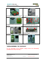
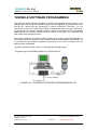
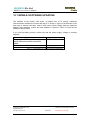
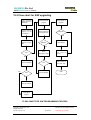
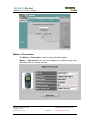
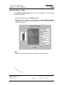
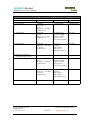
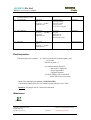
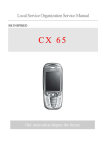
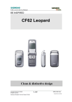
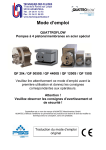
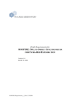
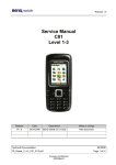
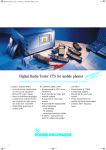
1
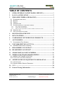
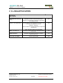
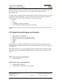
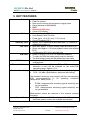
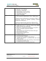
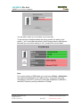
BE INSPIRED
Performance with an ATTITUDE!
Our Innovation Shapes the Future
SIEMENS Pte Ltd
S55/57 Level 2 Service Manual
TABLE OF CONTENTS
1
GPRS (GENERAL PACKET RADIO SERVICE).......................... 1
2
K-JAVA APPLICATION ................................................................. 2
3
MMS (MULITMEDIA MESSAGING)............................................ 3
3.1
3.2
3.3
3.4
3.5
STANDARD COMPLIANCE ..............................................................................3
BEARER ......................................................................................................3
DISPLAY .....................................................................................................3
PRESENTATION ...........................................................................................3
SUPPORTED MEDIA TYPES AND FORMATS.......................................................4
3.5.1
3.5.2
3.5.3
3.6
3.7
Text: (part of presentation) ..................................................................................................... 4
Audio: (part of presentation) .................................................................................................. 4
PIM: (no part of presentation, will be available via the start-screen) ..................................... 5
MESSAGE SIZE ............................................................................................5
NOT SUPPORTED FEATURES .........................................................................5
4
BLUETOOTH OVERVIEW ............................................................ 6
5
KEY FEATURES .............................................................................. 7
6
COMPARISON WITH PREVIOUS PRODUCTS.......................... 9
7
ACCESSORIES............................................................................... 10
7.1
8
ACCESSORIES PART NUMBER.....................................................................11
UNIT DESCRIPTION L55 TUNA ................................................. 12
8.1
S55/56/57 MECHANICAL DIAGRAM .............................................................13
9
DISASSEMBLY OF S55/56/57 ....................................................... 14
10
REASSEMBLY OF S55/56/57 ........................................................ 15
11
SPARE PARTS & PART NUMBERS............................................ 16
12
MOBILE SOFTWARE PROGRAMMING .................................. 17
12.1 MOBILE SOFTWARE UPDATING..........................................................18
12.2 FLOW CHART FOR S/W UPGRADING ............................................................19
13
SIEMENS SERVICE EQUIPMENT USER MANUAL................ 20
13.1 INTRODUCTION ..........................................................................................20
13.2 SIEMENS MOBILE SERVICE EQUIPMENT .......................................................20
14
PICS ................................................................................................. 20
15
General Testing Information………………………………………..24
Copyright © Siemens Pte. Ltd.
All rights reserved
ICM MP CCQ ASP/ASC
Siemenes Techincal Support Center
Contents Page 1
Internal Service Use Only
SIEMENS Pte Ltd
S55/57 Level 2 Service Manual
1 GPRS (GENERAL PACKET RADIO SERVICE)
PRS is a new non-voice value added services that allows information to be
sent and received across a GSM mobile telephone network. It supplements
today’s Circuit Switched Data (CSD) and Short Message Services (SMS).
GPRS involves overlaying a packet based air interface on the existing
circuit switched GSM network. This gives the option to use a packet-based data
service. The information is split into separated but related “packets” before being
transmitted and reassembled at the receiving end. Theoretically, maximum speeds
of up to 171.2 kilobits per second (kbps) are achievable with GPRS using all eight
timeslots at the same time. This is about 3 times as fast as the data transmission
speed possible over today’s fixed telecommunications networks and 10 times as fast
as current Circuit Switched Data services on GSM networks.
Figure1. Example of GPRS data transmission
Example: Cell with 1 Frequency channel:
1 physical channel for signalling, 4 physical channels for Circuit switched
and 3 physical channels for Packet switched
Copyright © Siemens Pte. Ltd.
All rights reserved
ICM MP CCQ ASP/ASC
Siemenes Techincal Support Center
1 of 28
Internal Service Use Only
SIEMENS Pte Ltd
S55/57 Level 2 Service Manual
2 K-JAVA APPLICATION
Java-based
game system
Java Application Manager
(JAM)
RAM for Java applications
Application launcher and download manager.
yes
Supports HTTP-based OTA download of applications
over GPRS and CSD.
Available RAM for Java applications (ie. program code
and data) during application runtime:
yes
Minimum: 100 Kbyte
(Has to be taken as working assumption for application
development.)
Goal: 145 Kbyte as SL45i (not committed)
MIDP 1.0, CLDC 1.0
'OEM extensions'
HTTP API over GPRS
As SL45i, including performance optimizations from
SL45i-Infusio.
yes
Proprietary API extensions as SL45i. Including
'Siemens Game API'
yes
SL45i: only over CSD
yes
Copyright © Siemens Pte. Ltd.
All rights reserved
ICM MP CCQ ASP/ASC
Siemenes Techincal Support Center
2 of 28
Internal Service Use Only
SIEMENS Pte Ltd
S55/57 Level 2 Service Manual
3 MMS (Mulitmedia Messaging)
3.1 Standard compliance
·
·
·
3GPP TS23.140 R99
WAP 205/ 206/ 209
MMS Conformance Document V2.0.0
3.2 Bearer
·
WAP 1.2.1 (incl. WAP-push and WTP SAR)
3.3 Display
·
·
·
Resolution: 101 x 80 pixels
Colour depth: 256 colours
Technology: C-STN
3.4 Presentation
MMS SMIL presentation (slide show) according to MMS Conformance Document
V2.0.0, MO and MT
Slide 1
Slide 2
Slide 3
Image
Slide n
+ sound
text
Figure 1: Structure of a multimedia message
According to the MMS Conformance Document V2.0.0 a presentation consists of one or
more slides. Each slide can consist of one or all of the following elements:
· Image
· Text
· Sound
Copyright © Siemens Pte. Ltd.
All rights reserved
ICM MP CCQ ASP/ASC
Siemenes Techincal Support Center
3 of 28
Internal Service Use Only
SIEMENS Pte Ltd
S55/57 Level 2 Service Manual
If other elements are used in a MM, these elements will not be shown in the presentation,
but can be accessed via a separate start-screen, that will be displayed after the
presentation stops.
If a MM contains a SMIL document and the MM is opened with the multi-event-icon the
presentation starts automatically. After the presentation stops, the phone will display a
separate start-screen. This screen will show the following elements:
· Sender
· CC
· Subject
· Availability of SMIL presentation
· List of MM elements not included in presentation
Out of this list you can select and store all elements provided in the list to the internal file
system.
3.5 Supported media types and formats
· Image: (part of presentation)
· JPEG baseline with JFIF as exchange format
· GIF 87a and GIF89a (including animated GIF)
· WBMP
· BMP
· PNG
Interoperability for images is guaranteed only for resolutions not exceeding 160x120,
while the device can handle images larger than this (exact boundary is given by memory,
not resolution).
GIF, JPEG and PNG type images exceeding display resolution will be downscaled while
maintaining aspect ratio. BMP and WBMP images exceeding display resolution will be
clipped.
3.5.1 Text: (part of presentation)
·
subset of unicode
3.5.2 Audio: (part of presentation)
·
·
AMR NB (decoding only)
General Midi 1.0 File format 0 and 1(.MID)
Copyright © Siemens Pte. Ltd.
All rights reserved
ICM MP CCQ ASP/ASC
Siemenes Techincal Support Center
4 of 28
Internal Service Use Only
SIEMENS Pte Ltd
S55/57 Level 2 Service Manual
3.5.3 PIM: (no part of presentation, will be available via the startscreen)
·
·
vCard V2.1
vCalendar V1.0
3.6 Message size
A message size of 40 kBytes MO and MT will be guaranteed.
3.7 Not supported features
·
·
·
·
·
·
AMR encoding
Read reply report
Delivery report
BCC addressing
MMS templates
OTAP of MMS parameters
Copyright © Siemens Pte. Ltd.
All rights reserved
ICM MP CCQ ASP/ASC
Siemenes Techincal Support Center
5 of 28
Internal Service Use Only
SIEMENS Pte Ltd
S55/57 Level 2 Service Manual
4 BLUETOOTH OVERVIEW
Bluetooth is a low-power, short-range wireless networking standard designed for local
area voice and data communications. Mobile computers, mobile phones and headsets,
PDAs and PCs, will all exchange information using the specification agreed to by the
over 2,400 companies in the Bluetooth Special Interest Group (SIG). The SIG companies
are working together to ensure interoperability between products and include some of the
top brands in wireless; names like 3Com, Ericsson, IBM, Intel, Lucent, Microsoft, Nokia,
Toshiba, and Motorola.
Bluetooth is a global de facto standard for wireless connectivity. Based on a low-cost,
short-range radio link, Bluetooth cuts the cords that used to tie up digital devices.
When two Bluetooth equipped devices come within 10 meters range of each other, they
can establish a connection together. And because Bluetooth utilizes a radio-based link, it
doesn't require a line-of-sight connection in order to communicate. Your laptop could
send information to a printer in the next room, or your microwave could send a message
to your mobile phone telling you that your meal is ready.
In the future, Bluetooth is likely to be standard in tens of millions of mobile phones, PCs,
laptops and a whole range of other electronic devices. As a result, the market is going to
demand new innovative applications, value-added services, end-to-end solutions and
much more. The possibilities opened up really are limitless, and because the radio
frequency used is globally available, Bluetooth can offer fast and secure access to
wireless connectivity all over the world. With potential like that, it's no wonder that
Bluetooth is set to become the fastest adopted technology in history.
Copyright © Siemens Pte. Ltd.
All rights reserved
ICM MP CCQ ASP/ASC
Siemenes Techincal Support Center
6 of 28
Internal Service Use Only
SIEMENS Pte Ltd
S55/57 Level 2 Service Manual
5 KEY FEATURES
General:
Battery:
Stand-by Time:
Talk Time:
·
·
·
·
·
·
·
·
·
·
·
·
·
·
GSM Antenna:
·
·
·
·
·
Bluetooth-Antenna:
·
Receiver Sensitivity:
·
·
SIM Card:
Hands free
Flash file system
New sound concept with polyphonic ringing tones
Kjava (identical to K45-Manta)
MMS
Bluetooth (S55 only)
Colour LCD display
Nominal Capacity 750mAh
LiIon Battery Pack 700 mAh
Power Input: 1.8 A (0.6 ms) / 0.2 A (4 ms)
Cut-off Threshold 3.2 V
approx. 250 h measured at BSPAMFRMS = 9; number of
neighbouring cells = 0
Best case approx. 5 hours (lowest output level with DTX)
Worst case approx. 2.5 hours (highest output level without
DTX)
Conditions for DTX: 40% user talk time
Small (=”Plug In“) 1.8 V or 3 V-SIM card (Phase II).
To insert the SIM the battery pack must be removed.
The SIM reader coding will be realized by lower case.
A triple band PIFA antenna will be an integral part of the
mobile phone.
A PCB antenna (Material FR4, SMD component,
thickness 4 mm) will be soldered on the main-PCB.
Operating range: Approx. 10 m
EGSM: -102 dBm (Specification; static and with fading)
PCN: -102 dBm (Specification; static and with fading)
The reception sensitivity must comply with the corresponding
GSM recommendations in all operating conditions
(temperature, battery level…).
·
·
EGSM: measurements according typical sensitivity are
not yet available
PCN: measurements according typical sensitivity are
not yet available
Measurement values are referred to the external antenna
connector.
Speech Coder: · Full Rate, Enhanced Full Rate, Adaptive Multi Rate and
Half Rate speech coders are available as standard.
Copyright © Siemens Pte. Ltd.
All rights reserved
ICM MP CCQ ASP/ASC
Siemenes Techincal Support Center
7 of 28
Internal Service Use Only
SIEMENS Pte Ltd
S55/57 Level 2 Service Manual
Display:
Transmitter Power:
·
·
·
·
·
·
·
·
·
Type: Full Graphic
Resolution: 101 X 80 Pixel
Illumination: 2 White LED
Active area/mm: 29.379 x 25.265
Visible area/mm: max. 32.4 x 28.9
Technology: Colour STN
Contrast: Adjustable
EGSM: nominal 2W (Specification: Class 4 Mobile phone)
PCN: nominal 1W (Specification: Class 1 Mobile phone)
Transmitter output characteristics is according to GSM 11.10
specification implying all specified operating conditions
(temperature, battery level…).
Keypad:
Acoustics:
Transmitter setpoints will be specified for GSM and PCN
when typical values and statistical values become available.
· Bridgeless
· 12-digit block (0-9, #, *) and two function keys (SEND,
END) in one block with small letters
· ON/OFF key combined with the END key; the symbol ¼ (I
inside O) is used as a symbol for ON/OFF.
· 2 soft keys
· 4-way navigation key designed as centred rocker type
· white as illumination colour
· printed lettering in three colours
· orientation at key “5“
· comfortable earpiece with optimal acoustics
· omni-directional microphone
· loud signal emitter (>95 dBa at 5cm distance)
· x different call melodies + y melodies either with internal
melody composer
· all melodies and sounds with increasing volume because
of the possible handsfree mode
· four different and one increasing volume level
Copyright © Siemens Pte. Ltd.
All rights reserved
ICM MP CCQ ASP/ASC
Siemenes Techincal Support Center
8 of 28
Internal Service Use Only
SIEMENS Pte Ltd
S55/57 Level 2 Service Manual
6 COMPARISON WITH PREVIOUS PRODUCTS
Feature
Supported
Systems
Stand-by
Time
Talk Time
Battery
Type /
Capacity
Weight
Volume
Length
Width
Thickness
SIM
Antenna
Antenna
Perform.
relative to
C25
SAR
related to
1g
Half Rate
Enhanced
Full Rate
AMR
Fax/Data
GPRS
Keypad
Illum.
Display /
Display
Illumination
Ringer
volume
level
P35 M / S
Dual Band
E-GSM 900 / GSM 1800
approx. 200 h (150 h)
U35
Dual Band
E-GSM 900 / GSM 1800
Up to 200 h
K45(88) ME45/S45
Dual Band
E-GSM 900 / GSM 1800
Up to 270 h
L55 Marlin
Triple band
E-GSM 900 /1800/1900
Up to 250 h
5 hours
Li-Ion
600 mAh
Up to 4 h
LI-Thin
540 mAh
Up to 5 h
LI-Ion Battery Pack
Nominal Cap. :840 mAh
Up to 6 h
LI-Ion Battery Pack
Nominal Cap.: 750 mAh
approx. 116 g (M35)
approx. 106 g (S35)
approx. 90 cm³ (M35)
approx. 99 cm³ (S35)
117.9 mm (M35)
117.9 mm (S35)
44.0 ... 45.8 mm (M35)
45.0 ... 46.9 mm (S35)
approx. 21.3 mm (M35)
approx. 22.6 mm (S35)
Plug-In 1.8V/3V
Integrated
0 dB @ 900 MHz
-0,3 dB @ 1800 MHz
approx. 85 g
approx. 99 g (ME45)
approx. 93 g (S45)
approx. 76 cm3 (ME45)
approx. 69 cm3 (S45)
108,9 mm (ME45)
108,9 mm (S45)
42.5 ... 45.5 mm (ME45)
42.0 ... 45.9 mm (S45)
19.5 ... 20.5 mm (ME45)
18.4 ... 19.5 mm (S45)
Plug-In 1.8V/3V
Integrated
-0,4 dB @ 900 MHz
-0,5 dB @ 1800 MHz
Approx. 95 g
approx. 69 cm3
105 mm (without
external antenna)
42 ... 46 mm
Approx. 17 mm
Plug-In 1.8V/3V
Fixed PCB
-0,4 dB @ 900 MHz
-0,3 dB @ 1800 MHz
(painted upper case)
-
-
1.5 W/kg @ 900 MHz
0.8 W/kg @ 1800 MHz
Yes
Yes
Yes
Yes
Yes
Yes
No
Yes
No
No
Yes
No
No
Yes
Yes, class 8
Yes
Yes
Yes
FSTN full dot matrix, 6
lines graphic + icons /
amber
Min. 95 dB(A) @ 5cm
Typ. >100 dB(A) @ 5cm
FSTN full dot matrix, 6
lines graphic + icons /
amber
min. 95 dB(A) @ 5 cm
FSTN full dot matrix, 6
lines graphic + icons /
amber
Min. 95 dB(A) @ 5cm
Typ. >100 dB(A) @ 5cm
Copyright © Siemens Pte. Ltd.
All rights reserved
ICM MP CCQ ASP/ASC
Approx. 69 cm3
101 mm
42.0 ... 46.0 mm
17.5 … 18.9 mm
Plug-In 1.8V/3V
Integrated
-0.4 dB @ 900 MHz
-0,3 dB @ 1800 MHz
-0,3 dB @ 1900 MHz
compared to S40
1.0 W/kg @ 900 MHz
0.8 W/kg @ 1800 MHz
0.8 W/kg @ 1900 MHz
Yes
Yes
Yes
Yes
Yes, class 8
class 10 tbc until S2
Yes, blue LED
CSTN full dot matrix, 6
lines graphic + icons /
white
Min. 95 dB(A) @ 5cm
Typ. >100 dB(A) @ 5cm
Max. 125 dB(A) @
human ear
Siemenes Techincal Support Center
9 of 28
Internal Service Use Only
SIEMENS Pte Ltd
S55/57 Level 2 Service Manual
7 ACCESSORIES
Due to changes on the connector from “Lumberg” to “Slim
Lumberg”, accessories using the old “Lumberg” connector will
not be able to be used on the new “Slim Lumberg” platform.
Note: PS note that this is only a Preliminary specification, for the actual
specification, PS refer to the E-commerce.
Copyright © Siemens Pte. Ltd.
All rights reserved
ICM MP CCQ ASP/ASC
Siemens Techincal Support Center
10 of 31
Internal Service Use Only
SIEMENS Pte Ltd
S55/57 Level 2 Service Manual
7.1 Accessories Part Number
Accessories Part Number
Note: For ALL ACCESSORIES PART NUMBERS, PS refer to the ECommerce for the latest updated copy.
Copyright © Siemens Pte. Ltd.
All rights reserved
ICM MP CCQ ASP/ASC
Siemens Techincal Support Center
11 of 31
Internal Service Use Only
SIEMENS Pte Ltd
S55/57 Level 2 Service Manual
8 UNIT DESCRIPTION L55 MARLIN
Marlin is designed as a single PCB-phone with a bridgeless keypad unit and
colour display. The mechanical design has been conceived to allow general use
of most of the electromechanical parts from K45 or L55 Tuna.
Full attention has been given to create a high sophisticated design showing
galvanized side-buttons, softkeys, navikey and earpiece cover. In a addition the
display lens with chrome ring. An additional design frame around the dsiplay lens
is introduced to realize a second colour without complicated spray and masking
process. The display lens is decorated from outside with IMD and anti scratch
protection.
Copyright © Siemens Pte. Ltd.
All rights reserved
ICM MP CCQ ASP/ASC
Siemens Techincal Support Center
12 of 31
Internal Service Use Only
SIEMENS Pte Ltd
S55/57 Level 2 Service Manual
8.1 S55/56/57 Mechanical Diagram
Copyright © Siemens Pte. Ltd.
All rights reserved
ICM MP CCQ ASP/ASC
Siemens Techincal Support Center
13 of 31
Internal Service Use Only
SIEMENS Pte Ltd
S55/57 Level 2 Service Manual
9 DISASSEMBLY OF S55/56/57
Step 1
Step 2
Front view of the S55/56/57
Step 3
Step 4
Remove the battery by lifting it upwards.
Step 5
Remove the battery by releasing the catching &
lifting it up sideway simultaneously.
Step 6
Remove the SIM card by sliding it upwards in
the direction shown.
Step 7
Back view of the S55/56/57
BACK
Remove the four screws on the back of the
phone as indicated by the red circles.
Step 8
FRONT
Separate the front & back casing by lifting the
back casing upwards. Always ensure that it is
opened back first, or the front casing might be
damaged.
The separated S55/56/S57
Copyright © Siemens Pte. Ltd.
All rights reserved
ICM MP CCQ ASP/ASC
Siemens Techincal Support Center
14 of 31
Internal Service Use Only
SIEMENS Pte Ltd
S55/57 Level 2 Service Manual
Step 9
Step 10
The keypad can be further seperated from the
front casing using a tweezer as per diagram.
The separated front housing & keypad module.
Step 9
Step 9
The keypad module can be further seperated
by releasing the hinges with a tweezer as
indicated.
When separating the keypad from the PCB,
ensure that the hinges are not broken,
otherwise, the keypad might not work properly.
Step 9
Step 10
Separate the RF board from the back casing.
Step 11
The LCD display could be further seperated
from the main board by releasing the catch in
the direction shown.
Step 12
The separated LCD & the RF board.
Fully disassembled S55/56/57
10 REASSEMBLY OF S55/56/57
For the reassembly of the S55/56/57, simply reverse the disassembly
procedures from Step 12 to Step 1.
Copyright © Siemens Pte. Ltd.
All rights reserved
ICM MP CCQ ASP/ASC
Siemens Techincal Support Center
15 of 31
Internal Service Use Only
SIEMENS Pte Ltd
S55/57 Level 2 Service Manual
11 SPARE PARTS & PART NUMBERS
Swap Unit
Spare Parts Level 1
Spare Parts Level 2
Spare Parts Level 2,5
Spare Parts Level 2,5e
Documentation and Software
Note: For ALL SPARE PARTS & PART NUMBERS, PS refer to the ECommerce for the latest updated copy.
Copyright © Siemens Pte. Ltd.
All rights reserved
ICM MP CCQ ASP/ASC
Siemens Techincal Support Center
16 of 31
Internal Service Use Only
SIEMENS Pte Ltd
S55/57 Level 2 Service Manual
12 MOBILE SOFTWARE PROGRAMMING
The common mobile software available is divided into language groups. However, this
software does not contain the specific settings, such as ringing tones, greeting text, short
dial list etc., required by the operator(s) or service provider(s). Therefore, it is not
uncommon to have some menu item(s) differ in different variants or are not visible at all.
These settings are stored in different memory area of the mobile and will be activated
depending on the customer specific model or variant of the phone by a separate test
step during the production process.
Due to this separation of common mobile software and customer specific initialization, it
is possible to fulfill the demands of the market requiring customization and flexibility. As
a consequence the software programming process in the LSO is divided into two
different steps as followed:
- Software update to actual version and appropriate language group
- Programming of CUSTOMER SPECIFIC INITIALIZATION
FIGURE 2.24 55 SERIES SOFTWARE PROGRAMMING SETUP
Copyright © Siemens Pte. Ltd.
All rights reserved
ICM MP CCQ ASP/ASC
Siemens Techincal Support Center
17 of 31
Internal Service Use Only
SIEMENS Pte Ltd
S55/57 Level 2 Service Manual
12.1 MOBILE SOFTWARE UPDATING
The software of the mobile, L55 series, is loaded from a PC directly. Hardware
interconnection between the mobile and the PC is shown in Figure 2.24 Because of the
new type of external connector used in L55 series (Slim-Lumberg type) an additional
adaptor cable between mobile and boot adaptor is required. Table 2.1 listed all the
hardware requirements
If you use the battery dummy, make sure that the power supply voltage is correctly
adjusted.
Description
Part No.
Bootadapter 2000 incl. AC-Adapter,
serial cable and mobile connection
cable
L36880-N9241-A200
IBM Compatible PC – Pentium
Adapter cable
F30032-P226-A1
TABLE 2.1 EQUIPMENT LIST FOR SOFTWARE PROGRAMMING.
Copyright © Siemens Pte. Ltd.
All rights reserved
ICM MP CCQ ASP/ASC
Siemens Techincal Support Center
18 of 31
Internal Service Use Only
SIEMENS Pte Ltd
S55/57 Level 2 Service Manual
12.2 Flow chart for S/W upgrading
Plug in the Boot
Adaptor to the PC
and Mobile
Start the SWUP
program
S/W upgrading in
progress
Connec t the AC
adaptor to the
Boot Adaptor
Select & Execute
the "Mobile S/W"
ERROR?
YES
NO
P o we r u p Bo o t
Adaptor & check
LED.
ERROR?
NO
TEST Mobile
YES
Check
H/W setup = S/W
Take note of error
and repeat
process
Check AC Adaptor
OK?
Feedback Error to
Tech. Supp. Dep
OK?
Correct Settings
OK?
YES
NO
YES
END
NO
Faulty AC Adaptor
Faulty Boot
Adaptor
FLOW CHART FOR S/W PROGRAMMING PROCESS
Copyright © Siemens Pte. Ltd.
All rights reserved
ICM MP CCQ ASP/ASC
Siemens Techincal Support Center
19 of 31
Internal Service Use Only
SIEMENS Pte Ltd
S55/57 Level 2 Service Manual
13 SIEMENS SERVICE EQUIPMENT USER
MANUAL
13.1 Introduction
Every LSO repairing Siemens handset must ensure that the quality standards are
observed. Siemens has developed an automatic testing system that will perform
all necessary measurements. This testing system is known as:
13.2 Siemens Mobile Service Equipment
Using this system vastly simplifies the repair of the phones and will make sure
that:
1. All possible faults are detected
2. Sets, which pass the test, will be good enough to return to customer.
Starting from the P35 Series, Siemens will introduce a simpler and faster testing
platform for testing a repaired Siemens mobile phone. The testing platforms are
either base on R&S CMD 53/55, CMU200 or CTS55/30 GSM test set.
There is also test software under development for testing with the Willtek 4400S,
4201/2S and the 4107 GSM test set.
THE LSO WILL HAVE TO PURCHASE THE SYSTEM, CHOOSING
BETWEEN THE COMPLETE PACKAGE OR SUB-SET OF IT.
A FULLY AUTOMATIC TEST PROCEDURE IS ONLY
POSSIBLE
IF
THE
COMPLETE
SYSTEM
IS
INSTALLED.
Make sure that your CTS firmware is Version 3.01 or higher. For
CMD 55 it must be Version 4.03 and higher. Please check with the
Service Info SB_0500 for the CTS/CMD Hardware Options.
Please refer to the technical support webpage in the ecommerce
website for test equipment related information.
Copyright © Siemens Pte. Ltd.
All rights reserved
ICM MP CCQ ASP/ASC
Siemens Techincal Support Center
20 of 31
Internal Service Use Only
SIEMENS Pte Ltd
S55/57 Level 2 Service Manual
14 PICS
PICS Internet
Overview
The following functions are available for the LSO
· Generate PINCODE
· Generate SIMLOCK-UNLOCK-Code
· Print IMEI labels
The access to the server which is located in Kamp-Lintfort is protected
and will only be granted to authorized users being supplied with a special
coded chipcard.
Chipcards and the administration services of the PICS database are
provided by PICS- TRUST- Center at department ICP MP OI KampLintfort.
In case of any questions or requests concerning chipcards or
administration of the database please ask your responsible Siemens
Customer Care Manager.
Copyright © Siemens Pte. Ltd.
All rights reserved
ICM MP CCQ ASP/ASC
Siemens Techincal Support Center
21 of 31
Internal Service Use Only
SIEMENS Pte Ltd
S55/57 Level 2 Service Manual
Installation for Windows 95 / 98 / NT / 2000
Requirements
In order to use the PICS-Internet websites you need a fully configured
internet access with a 32bit NETSCAPE-Browser.
Remark:
Microsoft Internet Explorer and Netscape versions above 4.7x cannot be
used!
There is a 90-day-trial-version of Netscapes Navigator 4.6 in english or
german available on the PICS installation CD provided by Siemens.
Every user is responsible for a proper installation matching the
license agreements.
For installation and further access you need the following:
1. The Installation-CD which contains:
·
the SETUP programm for the InterSEC plugin
·
the trial version of Netscape Navigator 4.6 (german / english)
·
the german / english documentation
2. A chipcard which is authorised by ICP MP OI KLF in order to decode
the protected PICS Websites (and a password which gives you access
to your chipcard). Chipcards can be ordered via your responsible
Customer Care Manager within Siemens.
3. A supported chipcard reader (Smarty or Siemens B1) in order to
access your chipcard.
Remark:
We recommend to use Siemens B1 reader. Similar device to B1 is
Cardman 9010.
Generate Codes
In the module „Generate Codes“ you can choose to generate:
- Master - Phonecodes
- Simlock Unlock - Codes
Copyright © Siemens Pte. Ltd.
All rights reserved
ICM MP CCQ ASP/ASC
Siemens Techincal Support Center
22 of 31
Internal Service Use Only
SIEMENS Pte Ltd
S55/57 Level 2 Service Manual
Master - Phonecodes
The Master – Phonecode is used to unlock blocked mobiles.
Master – Phonecodes can only be supplied for mobiles which have
been delivered in a regular manner.
Copyright © Siemens Pte. Ltd.
All rights reserved
ICM MP CCQ ASP/ASC
Siemens Techincal Support Center
23 of 31
Internal Service Use Only
SIEMENS Pte Ltd
S55/57 Level 2 Service Manual
Simlock Unlock - Code
The Simlock-Unlock-Codes can only be generated if the following
conditions are given:
- Mobile must have an active Simlock inside.
- The user must be given the authorization to obtain Simlock UnlockCodes for the variant of the operator to which the mobile was
delivered last time.
Hint:
If there's no such authorization you'll get the following screen:
Copyright © Siemens Pte. Ltd.
All rights reserved
ICM MP CCQ ASP/ASC
Siemens Techincal Support Center
24 of 31
Internal Service Use Only
SIEMENS Pte Ltd
S55/57 Level 2 Service Manual
In this case please contact your responsible Siemens Customer Care
Manager.
Printing IMEI label
The module „Print IMEI label“ offers the possibility to print IMEI labels
for mobiles again.
Copyright © Siemens Pte. Ltd.
All rights reserved
ICM MP CCQ ASP/ASC
Siemens Techincal Support Center
25 of 31
Internal Service Use Only
SIEMENS Pte Ltd
S55/57 Level 2 Service Manual
You are able to print up to six labels in just one step.
To prevent that misaligned labels are being printed, the setting "test
printer = Yes" is activated as default. After having printed a well-aligned
test label you can switch setting to "No" and print the correct label.
Hint:
For correct printing of IMEI labels you must have a Zebra - labelprinter
with special material that fits for label printing. This printer has to be
connected to local LPT1 printer port (also see Installation of IMPRINT)
and MUST feature a printing resolution of 300dpi.
Copyright © Siemens Pte. Ltd.
All rights reserved
ICM MP CCQ ASP/ASC
Siemens Techincal Support Center
26 of 31
Internal Service Use Only
SIEMENS Pte Ltd
S55/57 Level 2 Service Manual
15 General Testing Information
General Information
The technical instruction for testing GSM mobile phones is to ensure the best repair
quality.
Validity
This procedure is to apply for all from Siemens AG authorized level 2 up to 2.5e
workshops.
Procedure
All following checks and measurements have to be carried out in an ESD protected
environment and with ESD protected equipment/tools. For all activities the international
ESD regulations have to be considered.
Get delivery:
Ø Ensure that every required information like fault description, customer data
a.s.o. is available.
Ø Ensure, that the packing of the defective items is according to packing
requirements
Ø Ensure that there is a description available, how to unpack the defective items
and what to do with them.
Enter data into your database:
(depends on your application system)
Ø Ensure that every data, which is required for the IRIS-Reporting is available in
your database
Ø Ensure that there is a description available for the employees how to enter the
data
Incoming check and check after assembling:
!! Verify the customers fault description !!
Copyright © Siemens Pte. Ltd.
All rights reserved
ICM MP CCQ ASP/ASC
Siemens Techincal Support Center
27 of 31
Internal Service Use Only
SIEMENS Pte Ltd
S55/57 Level 2 Service Manual
Ø After an successful verification pass the defective item to
the responsible troubleshooting group.
Ø If the fault description can not be verified, perform additional tests to save time
and to improve repair quality
-
Switch on the device and enter PIN code if necessary unblock phone
Check the function of all keys including side keys
Check the display for error in line and row, and for illumination
Check the ringer/loudspeaker acoustics by individual validation
Check the IRDA Interface/Camera and Bluetooth
Perform a GSM Test as described in chapter 3.7
Check the storage capability:
Ø
Ø
Ø
Ø
Check internal resistance and capacity of the battery
Check battery charging capability of the mobile phone
Check charging capability of the power supply
Check current consumption of the mobile phone in different mode
Visual inspection:
Ø Check the entire board for liquid damages
Ø Check the entire board for electrical damages
Ø Check the housing of the mobile phone for damages
SW update:
Ø Carry out a software update and data reset according to the master tables and
operator/customer requirements.
Copyright © Siemens Pte. Ltd.
All rights reserved
ICM MP CCQ ASP/ASC
Siemens Techincal Support Center
28 of 31
Internal Service Use Only
SIEMENS Pte Ltd
S55/57 Level 2 Service Manual
GSM Test:
-
Connect the mobile/board via internal antenna (antenna coupler) and external
antenna (car cradle) to a GSM tester
Use a Test SIM
Skip GSM 900/GSM1800 or GSM1900 test cases if not performed by the mobile
phone
Internal Antenna
Test case
Parameter
Measurements
Limits
• individual check
1
Location Update
• GSM900
• BS Power = -55 dBm
• middle BCCH
• Display check
2
Call from BS
• low TCH
• PCL 5
• BS Power = -55 dBm
• middle BCCH
• Ringer/Loudspeaker check • individual check
3
TX GSM900
• low TCH
• PCL 5
• BS Power = -55 dBm
• middle BCCH
• Frequency Error
• Phase Error RMS
• Phase Error Peak
• Average Power
• Power Time Template
• GSM Spec.
4
Handover to GSM1800
Including Handover Check
5
TX GSM1800
• low TCH
• PCL 0
• BS Power = -55 dBm
• middle BCCH
• Frequency Error
• Phase Error RMS
• Phase Error Peak
• Average Power
• Power Time Template
• GSM Spec.
6
Handover to GSM1900
Including Handover Check
7
TX GSM1900
• low TCH
• PCL 0
• BS Power = -55 dBm
• middle BCCH
• Frequency Error
• Phase Error RMS
• Phase Error Peak
• Average Power
• Power Time Template
• GSM Spec.
8
Call relaese from BS
Copyright © Siemens Pte. Ltd.
All rights reserved
ICM MP CCQ ASP/ASC
Siemens Techincal Support Center
29 of 31
Internal Service Use Only
SIEMENS Pte Ltd
S55/57 Level 2 Service Manual
External Antenna
Test case
Parameter
Measurements
Limits
9 Call from MS
• GSM900
• high TCH
• PCL 6
• BS Power = -55 dBm
• middle BCCH
• Keyboard check
• individual check
10 TX GSM900
• high TCH
• PCL 6
• BS Power = -55 dBm
• middle BCCH
• Frequency Error
• GSM Spec.
• Phase Error RMS
• Phase Error Peak
• Average Power
• Power Time Template
11 RX GSM900
• high TCH
• BS Power = -102 dBm
• 50 Frames
• middle BCCH
• RX Level
• RX Qual
• BER Class Ib
• BER Class II
• BER Erased Frames
13 TX GSM1800
• high TCH
• PCL 1
• BS Power = -55 dBm
• middle BCCH
• Frequency Error
• GSM Spec.
• Phase Error RMS
• Phase Error Peak
• Average Power
• Power Time Template
14 RX GSM1800
• high TCH
• BS Power = -102 dBm
• 50 Frames
• middle BCCH
• RX Level
• RX Qual
• BER Class Ib
• BER Class II
• BER Erased Frames
• GSM Spec.
12 Handover to GSM1800
Including Handover Check
• GSM Spec.
15 Call relaese from MS
Copyright © Siemens Pte. Ltd.
All rights reserved
ICM MP CCQ ASP/ASC
Siemens Techincal Support Center
30 of 31
Internal Service Use Only
SIEMENS Pte Ltd
S55/57 Level 2 Service Manual
16 Handover to GSM1900
Including Handover Check
17 TX GSM1900
• high TCH
• PCL 1
• BS Power = -55 dBm
• middle BCCH
• Frequency Error
• Phase Error RMS
• Phase Error Peak
• Average Power
• Power Time Template
• GSM Spec.
18 RX GSM1900
• high TCH
• BS Power = -102 dBm
• 50 Frames
• middle BCCH
• RX Level
• RX Qual
• BER Class Ib
• BER Class II
• BER Erased Frames
• GSM Spec.
19 Echo Test
• high TCH
• PCL 1
• BS Power = -70 dBm
• middle BCCH
• individual check
Final Inspection:
The final inspection contains: 1) a 100% network test (location update, and
set up call).
2) Refer to point 3.3
3) a random sample check of :
- data reset (if required)
- optical appearance
- complete function
4) Check if PIN-Code is activated
delete PIN-Code if necessary
Basis is the international standard of DIN ISO 2859.
Use Normal Sample Plan Level II and the Quality Border 0,4 for LSO.
Remark: All sample checks must be documented.
Attachment
Sampling.xls
Copyright © Siemens Pte. Ltd.
All rights reserved
ICM MP CCQ ASP/ASC
Siemens Techincal Support Center
31 of 31
Internal Service Use Only