1
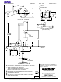
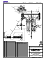
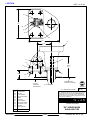
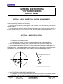
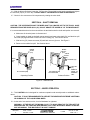
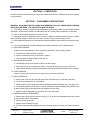
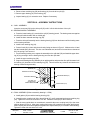
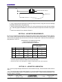
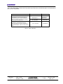
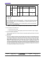
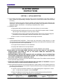
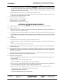
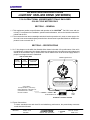
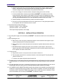
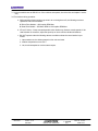
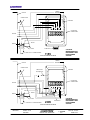
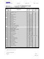
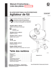
MODELS EV1P25 thru EV1P75 MANUAL INSTRUCTIONS INSTALLATION OPERATION MAINTENANCE Book No. 1563 INSTRUCTION MANUAL MODELS EV1P25 thru EV1P75 TABLE OF CONTENTS MANUAL 1563 TITLE PAGE SAFETY CHECK LIST . . . . . . . . . . . . . . . . . . . . . . . . . . . . . . . . . . . . . . . . . . . . . . . . . . . . . . . . . . . IT-- 2144 DIMENSION DRAWING . . . . . . . . . . . . . . . . . . . . . . . . . . . . . . . . . . . . . . . . . . . . . . . . . . . . . . . . DS-- P-- 70 ASSEMBLY DRAWING . . . . . . . . . . . . . . . . . . . . . . . . . . . . . . . . . . . . . . . . . . . . . . . . . . . . . . . . . . L-- 17094 “EV” SERIES BUNG ADAPTER . . . . . . . . . . . . . . . . . . . . . . . . . . . . . . . . . . . . . . . . . . . . . . . . . . DS-- P-- 72 GENERAL INSTRUCTIONS “EV” SERIES MIXER DIRECT DRIVE . . . . . . . . . . . . . . . . . . . . . . . IT-- 3694 INITIAL INSPECTION, SHIPPING ARRANGEMENT . . . . . . . . . . . . . . . . . . . . . . . . . . . SECTION-- 1 MIXER INSTALLATION . . . . . . . . . . . . . . . . . . . . . . . . . . . . . . . . . . . . . . . . . . . . . . . . . . . SECTION-- 2 SHAFT AND IMPELLER INSTALLATION . . . . . . . . . . . . . . . . . . . . . . . . . . . . . . . . . . . . . SECTION-- 3 SHAFT REMOVAL . . . . . . . . . . . . . . . . . . . . . . . . . . . . . . . . . . . . . . . . . . . . . . . . . . . . . . . SECTION-- 4 MIXER OPERATION . . . . . . . . . . . . . . . . . . . . . . . . . . . . . . . . . . . . . . . . . . . . . . . . . . . . . SECTION-- 5 LUBRICATION . . . . . . . . . . . . . . . . . . . . . . . . . . . . . . . . . . . . . . . . . . . . . . . . . . . . . . . . . . SECTION-- 6 DISASSEMBLY INSTRUCTIONS . . . . . . . . . . . . . . . . . . . . . . . . . . . . . . . . . . . . . . . . . . . SECTION-- 7 ASSEMBLY INSTRUCTIONS . . . . . . . . . . . . . . . . . . . . . . . . . . . . . . . . . . . . . . . . . . . . . . SECTION-- 8 AIR MOTOR REQUIREMENTS . . . . . . . . . . . . . . . . . . . . . . . . . . . . . . . . . . . . . . . . . . . . . SECTION-- 9 AIR MOTOR LUBRICATION . . . . . . . . . . . . . . . . . . . . . . . . . . . . . . . . . . . . . . . . . . . . . . SECTION-- 10 MODEL NO. 2 AND 4 AIR MOTOR DRIVE ASSEMBLY . . . . . . . . . . . . . . . . . . . . . . . . . . . . . . . L-- 17617 NON-- LUBRICATED AIR MOTOR INSTRUCTIONS . . . . . . . . . . . . . . . . . . . . . . . . . . . . . . . . . . . . IT-- 3710 AIR MOTOR REQUIREMENTS . . . . . . . . . . . . . . . . . . . . . . . . . . . . . . . . . . . . . . . . . . . . . SECTION-- 1 USE OF AIR MOTOR IN HAZARDOUS ATMOSPHERE . . . . . . . . . . . . . . . . . . . . . . . . SECTION-- 2 ELECTRIC MOTOR INSTRUCTIONS . . . . . . . . . . . . . . . . . . . . . . . . . . . . . . . . . . . . . . . . . . . . . . . IT-- 2588 INITIAL INSPECTION . . . . . . . . . . . . . . . . . . . . . . . . . . . . . . . . . . . . . . . . . . . . . . . . . . . . SECTION-- 1 MOTOR MAINTENANCE AND STORAGE . . . . . . . . . . . . . . . . . . . . . . . . . . . . . . . . . . . . SECTION-- 2 OPERATING INSTRUCTIONS LIGHTNIN VARI-- MIX DRIVE (VM SERIES) . . . . . . . . . . . . . . . . IT-- 5252 (WITH BALDOR MOTOR) GENERAL . . . . . . . . . . . . . . . . . . . . . . . . . . . . . . . . . . . . . . . . . . . . . . . . . . . . . . . . . . . . . . SECTION-- 1 SPECIFICATIONS . . . . . . . . . . . . . . . . . . . . . . . . . . . . . . . . . . . . . . . . . . . . . . . . . . . . . . . SECTION-- 2 INSTALLATION & OPERATION . . . . . . . . . . . . . . . . . . . . . . . . . . . . . . . . . . . . . . . . . . . . SECTION-- 3 i INSTRUCTION MANUAL MODELS EV1P25 thru EV1P75 TABLE OF CONTENTS MANUAL 1563 TITLE PAGE OPERATING INSTRUCTIONS LIGHTNIN VARI-- MIX DRIVE (VM SERIES) . . . . . . . . . . . . . . . . IT-- 2023 (WITH RELIANCE MOTOR) GENERAL . . . . . . . . . . . . . . . . . . . . . . . . . . . . . . . . . . . . . . . . . . . . . . . . . . . . . . . . . . . . . . SECTION-- 1 SPECIFICATIONS . . . . . . . . . . . . . . . . . . . . . . . . . . . . . . . . . . . . . . . . . . . . . . . . . . . . . . . SECTION-- 2 INSTALLATION & OPERATION . . . . . . . . . . . . . . . . . . . . . . . . . . . . . . . . . . . . . . . . . . . . SECTION-- 3 RECOMMENDED SPARE PARTS EV “P” SERIES DIRECT . . . . . . . . . . . . . . . . . . . . . . . . . . . . . IT-- 3711 LIGHTNINR U.S. SALES OFFICE DIRECTORY . . . . . . . . . . . . . . . . . . . . . . . . . . . . . . . . . . . . . IT-- 3839 IT-- 5203 6-- 27-- 03 ii SAFETY CHECK LIST IMPORTANT All LIGHTNIN Mixers and Aerators are provided with properly designed lifting devices and safety covers to avoid potential injury and/or equipment damage. The following SAFETY CHECK LIST should be THOROUGHLY REVIEWED AND ADHERED TO before operating or performing maintenance on the mixer. FAILURE TO FOLLOW THESE INSTRUCTIONS COULD RESULT IN SERIOUS INJURY. 1. Use only the lifting device provided on your unit to install the mixer. Use shouldered eyebolts and tighten securely to handle component parts. We strongly recommend that the hoist rings be of safety swivel type with 360° rotational capability. 2. DO NOT connect the motor to the power source until all components are assembled, the mixer is installed, and all hardware is tightened to the proper torque which is specified in the operation and maintenance manuals supplied by LIGHTNIN. 3. DO NOT operate shaft sealing devices at temperatures or pressures higher than those specified in the manual or on the nameplates. 4. DO NOT service the mixer until you have followed your ”Control of Hazardous Energy Sources” (lockout, tagout procedure) as required by OSHA 29 CFR Part 1910. 5. DO NOT touch rotating mixer parts. 6. DO NOT operate mixer for service other than its intended use. 7. DO NOT make any field changes or modifications (horsepower, output speed, shaft lengths, impellers, etc.) without reviewing the changes with your LIGHTNIN Sales Representative or the LIGHTNIN Customer Service Department. 8. DO NOT install an aftermarket Variable Frequency Drive without first consulting your LIGHTNIN Sales Representative or the LIGHTNIN Customer Service Department to determine the compatibility of the existing motor with the Variable Frequency Drive. 9. DO NOT operate mixer until you have checked the following items: A. Make sure the mixer is properly grounded. B. Ensure all protective guards and covers are installed. C. Ensure all detachable components are securely coupled to the mixer. D. Thoroughly REVIEW and ADHERE TO the mixer operating instructions supplied by LIGHTNIN. E. Ensure the mixer output shaft rotates freely by hand. F. Ensure all personnel and equipment are clear of rotating parts. G. Ensure all external connections (electrical, hydraulic, pneumatic, etc.) have been completed in accordance with all applicable codes and regulations. 10. DO NOT enter the mixing vessel UNLESS: A. The mixer power supply is locked out (follow Item number 4). B. The mixer shaft is firmly attached to the mixer drive or the shaft is supported securely from below. C. You have followed applicable confined space regulations. REVISION C DATE 5–9–86 REVISED 6–15–95 LIGHTNIN MIXERS AND AERATORS LIGHTNIN 1986 INST. NO. IT–2144 PAGE 1 OF 1 SALES DATA BOOK SEC. 0.6 PAGE 3.00 7–3/4 DATE 11–30–01 11/16 DIA. MOUNTING HOLES 4 HOLES 20° 1 20° 1 6–5/8 DIA. 2–9/16 1.97 3.54 ELECTRIC MOTOR 5.90 7.50 AIR MOTOR 5–1/2 CL 9/16 2–3/8 OPTIONAL MOUNTING PLATE (REPLACES CLAMP) 16–1/2 MAX. 5 3/8” PIPE THREADS 11–5/8 MAX. 1/4 2–5/8 3–3/4 MOUNTING SURFACE 2–11/16 3–1/16 3–1/4 2–15/16 MAX. ADJUSTABLE NOTES: 1 UNIT OFFSET 20° HORIZONTALLY AND ADJUSTABLE 10° (OR MORE) VERTICALLY. UNIT ALSO AVAILABLE WITH 0° OFFSET. 2 WEIGHT (LESS SHAFT AND IMPELLERS): DIRECT DRIVE WITH ELECTRIC MOTOR : 44 LBS MAX. DIRECT DRIVE WITH AIR MOTOR: 29 LBS MAX. 3 DIMENSIONS ARE FOR REFERENCE ONLY UNLESS CERTIFIED. 4 ALL DIMENSIONS IN INCHES. 5 ADD APPROX. 2–1/4” TO HEIGHT WHEN USING 1/4 HP VARIABLE SPEED MOTOR 123998PSP. ALL EQUIPMENT DESIGN AND APPLICATION DATA SHOWN HEREIN AND RELATED KNOW-HOW IS CONFIDENTIAL AND THE PROPERTY OF THE LIGHTNIN GROUP OF COMPANIES. NO USE OR DISCLOSURE THEREOF MAY BE MADE WITHOUT OUR WRITTEN PERMISSION. R MIXERS AND AERATORS ISO 9001 CERTIFIED LIGHTNIN 1996 Certified By __________________________________ Date _________________ DIMENSION DRAWING EV “P” SERIES MIXER DIRECT DRIVE AIR OR ELECTRIC MOTOR DRAWING NO. DS–P–70B SALES DATA BOOK SEC. 0.6 PAGE 5.00 DATE 11–5–96 122 115 101 22 123 36 121 120 63 65 59 64 61 60 36 45 58 39 72 40 41 115 44 72 59 35 42 231 116 119 118 231 MIXER SHAFT 123 ROTATIONAL INSERT 61 FLAT WASHER (4) 122 HEX LOCKNUT 60 SOCKET HEAD CAP SCREW (4) 121 FLAT WASHER 59 RETAINING RING 120 HEX HEAD CAP SCREW 58 HEX SOCKET SET SCREW – NYLOK 119 RETAINING RING 45 BALL BEARING 118 CUP WASHER 44 RETAINING RING 116 CLAMP SCREW 42 OIL SEAL 115 TANK CLAMP 41 BALL BEARING 101 MOTOR 40 LANYARD 72 HEX WRENCH 39 EXPANSION PLUG 65 MOTOR COUPLING INSERT 36 HOUSING 64 MOTOR COUPLING HALF 35 DRIVE QUILL 63 MOTOR COUPLING HALF 22 GASKET ITEM PART NAME ITEM PART NAME ISO 9001 CERTIFIED LIGHTNIN 1996 ALL EQUIPMENT DESIGN AND APPLICATION DATA SHOWN HEREIN AND RELATED KNOW-HOW IS CONFIDENTIAL AND THE PROPERTY OF THE LIGHTNIN GROUP OF COMPANIES. NO USE OR DISCLOSURE THEREOF MAY BE MADE WITHOUT OUR WRITTEN PERMISSION. R MIXERS AND AERATORS ASSEMBLY DRAWING EV “P” SERIES MIXER DIRECT DRIVE BEARING HOUSING ASSEMBLY DRAWING NO. L–17094B LIGHTNIN SALES DATA BOOK SEC. DATE 10–25–96 PAGE 122 7.75 123 36 121 120 7.81 36 3.75 53 231 150 5.0” SHAFT EXT. 151 2.25 3 153 152 .75” APPROX. THREADED ENGAGEMENT TANK MOUNTING SURFACE BY OTHERS CERTIFIED ALL DIMENSIONS IN INCHES. 122 121 MIXER SHAFT LOCKWASHER HEX NUT PLAIN WASHER HX HD CAP SCREW INSERT LOCK NUT PLAIN WASHER 120 53 36 HX HD CAP SCREW MOUNTING PLATE HOUSING 231 153 152 151 150 123 3 ITEM Certified By ISO 9001 (2" NPT THREADS) C LIGHTNIN 1996 ALL EQUIPMENT DESIGN AND APPLICATION DATA SHOWN HEREIN AND RELATED KNOW-HOW IS CONFIDENTIAL AND THE PROPERTY OF THE LIGHTNIN GROUP OF COMPANIES. NO USE OR DISCLOSURE THEREOF MAY BE MADE WITHOUT OUR WRITTEN PERMISSION. MIXERS AND AERATORS DIMENSION DRAWING BUNG ADAPTER ”EV” SERIES MIXER BUNG ADAPTER PART NAME Date DRAWING NO. DS–P–72A GENERAL INSTRUCTIONS ”EV” SERIES MIXERS DIRECT DRIVE SECTION 1 – INITIAL INSPECTION, SHIPPING ARRANGEMENTS 1. 1 Check the shipping crates and your LIGHTNIN equipment for possible shipping damage. Report any damage immediately to the carrier and our factory. 1. 2 The mixer and impellers are packed together. The mixer shaft, if over 48 inches long, is packed in a separate container. 1. 3 Do not remove any protective coatings or wrappings until the mixer is ready to be put into service. If the mixer is to be stored, store only in an indoor, clean, dry location with controlled temperatures of 15° C to 40° C (59° F to 104° F). SECTION 2 – MIXER INSTALLATION 2. 1 Refer to Installation drawing for: a. Proper mixer mounting and location. b. Proper minimum impeller off–bottom and relative spacing for dual impeller applications. 2. 2 Lock–out power before positioning mixer, and review safety instructions before starting mixer. 2. 3 The clamp and beamplate are cast offset at recommended 20° horizontal plane and adjustable 0–10° in the vertical plane. Clamp and beamplate are also available with zero degree offset in the horizontal plane and adjustable 0–10° in the vertical plane. Refer to Table 1 for recommended angular positions. 80° 20° Table 1 – Mixer positioning 2. 4 BOLT TIGHTENING TORQUE RECOMMENDATIONS a. Inadequately or improperly tightened hardware can loosen due to vibration or the reactions imposed by fluid forces. This can result in reduced equipment service life or damage and failure. REVISION DATE 5/15/95 INST. No. IT–3694 1996 A LIGHTNIN REVISED 3/18/96 MIXERS AND AERATORS PAGE 1 OF 7 b. Recommended torques for tightening the bolts and screws on your LIGHTNIN mixer are listed with assembly instructions. Use of a torque wrench is recommended to ensure compliance with torque recommendations. c. The amount of torque required to maintain a tight connection can vary considerable for bolts of the same size under different operating conditions. Variations such as basic joint design, compression factors, type and strength of base and hardware material, surface finish of mating parts and lubrication are only some of the factors that influence the tightness of bolted connections for given torque values. d. All bolts should be coated with oil, grease, or an anti–seize compound whenever possible. The threads and bearing face of bolt heads and/or nuts should be lubricated. e. ALL BOLTS SHOULD BE RETIGHTENED AFTER THE UNIT HAS BEEN RUN UNDER LOAD FOR TWO (2) WEEKS, AND AT EACH SCHEDULED SHUT–DOWN THEREAFTER. f. Unless otherwise specified, it is recommended that metric commercial standard class 8.8 bolts and screws, and class 8 nuts be used for all bolted connections. For inch hardware use GR5. SECTION 3 – SHAFT AND IMPELLER INSTALLATION 3. 1 Install the impeller(s) on the mixer shaft (231) by tightening the set screws in the impeller hub. Refer to the installation drawing for recommended dual impeller spacing if two impellers are supplied. Refer to Impeller Assembly drawing for general impeller orientation. 3. 2 Clean the mixer shaft (231) end and drive quill (51) thoroughly. 3. 3 Orient the drive quill so that the set screw (58) aligns with the hole in the bearing housing (36). Align quill shaft by inserting lower shaft (231) into quill and rotate quill manually. 3. 4 Grasp mixer shaft approximately 20 inches below the shaft top and insert the mixer shaft completely into the drive quill, until it contacts the top of the quill bore. Align flat on shaft with set screw (58). Tighten set screw (58). MIXER SHAFT (231) DRIVE QUILL (35) HOUSING (36) SET SCREW (58) INSTALLATION POSITION HEX KEY (72) REMOVE PRIOR TO RUNNING UNIT Figure 1 – Shaft Installation 3. 5 DRIVE QUILL ORIENTATION a. NORMAL LIGHT CONDITIONS – Rotate the drive quill until the set screw (58) aligns with the access hole in the housing (36). Rotate drive quill by inserting lower shaft into drive quill and rotating by hand. b. LOW LIGHT CONDITIONS – If the mixer shaft is being installed in low light conditions, the drive quill can be oriented by feel. Insert lower shaft into drive quill and rotate the drive quill (35) by hand until the set screw (58) can be felt with the hex wrench through the access opening. REVISION DATE 5/15/95 INST. No. IT–3694 1996 A LIGHTNIN REVISED 3/18/96 MIXERS AND AERATORS PAGE 2 OF 7 3. 6 With the drive quill oriented, insert the 7/32” hex key (72) provided into the housing opening and tighten the set screw (58) to (15–30 ft–lbs). DO NOT IMPACT THE WRENCH OR USE AN EXTENSION. 3. 7 Check for free movement of all components by rotating the mixer shaft. SECTION 4 – SHAFT REMOVAL CAUTION: THE UPPER PORTION OF THE MIXER SHAFT (231) MAY BE HOT TO THE TOUCH. ONCE REMOVED FROM THE DRIVE QUILL (35), DO NOT GRASP THE UPPER 20” OF THE MIXER SHAFT. It is recommended that the mixer be removed from the tank before shaft or shaft and impeller are removed. a. Make sure all electrical power is disconnected. b. Grasp impeller by hand (or shaft with a strap wrench) and rotate mixer shaft (231) until the drive quill set screw (58) aligns with the access hole in the housing (36). See Caution above. c. With hex key (72) loosen set screw (58) and back out two (2) turns. See Figure 2. d. Remove mixer shaft from quill. See Caution above. MIXER SHAFT (231) DRIVE QUILL (35) MIXER SHAFT (231) DRIVE QUILL (35) HOUSING (36) SET SCREW (58) HOUSING (36) SET SCREW (58) DIS–ENGAGED HEX KEY (72) REMOVE PRIOR TO RUNNING UNIT Release Position Operating Position Figure 2 – Shaft Removal SECTION 5 – MIXER OPERATION 5. 1 This LIGHTNIN mixer is designed for continuous operation and normally needs no additional maintenance. CAUTION: IT IS NOT RECOMMENDED TO OPERATE THE MIXER WITH EXTREME VORTEXING OR SURGING OF THE LIQUID BEING MIXED. 5. 2 At the end of two weeks service, check all hardware for tightness. WARNING: AT THE END OF THE MIXING CYCLE, IT IS GOOD PRACTICE TO TURN OFF THE MIXER BEFORE THE TANK HAS BEEN DRAINED TO A LEVEL WHICH WILL RESULT IN EXCESSIVE SPLASHING. THIS MAY RESULT IN SHAFT DAMAGE. REVISION DATE 5/15/95 INST. No. IT–3694 1996 A LIGHTNIN REVISED 3/18/96 MIXERS AND AERATORS PAGE 3 OF 7 SECTION 6 – LUBRICATION All mixer bearings are the sealed type and are pre–packed with lubricant. Relubrication of these bearings is not necessary. SECTION 7 – DISASSEMBLY INSTRUCTIONS WARNING: DISCONNECT MOTOR LEADS OR OTHERWISE LOCK–OUT POWER SUPPLY BEFORE SERVICING THE MIXER. EYE PROTECTION MUST BE WORN. 7. 1 This mixer is precision manufactured and assembled to provide long trouble free service when properly maintained. If it becomes necessary to disassemble the unit, careful precise reassembly is necessary. 7. 2 Refer to the assembly drawings for location of parts. 7. 3 Equipment that will be required to service the mixer, in addition to standard mechanics tools is, a rubber mallet, retaining ring pliers, metric and ”inch” allen wrenches, arbor press and torque wrench. 7. 4 When disassembling the mixer, clean external surfaces adjacent to prevent dirt from entering the housings. 7. 5 It is recommended that oil seals and gaskets be replaced when the mixer is disassembled. 7. 6 SEAL REPLACEMENT Inspect oil seals and gaskets for nicks, gouges and deformities. When replacing seals: a. Coat the lips of seals with bearing grease. b. Install oil seal with lip facing up as shown in Figure 3. c. Coat the section of shaft sealing surface with oil. 7. 7 BEARING REPLACEMENT a. Old bearings can be removed with a puller or an arbor press. b. New bearings can be pressed on the shafts. Be careful to apply load only to the inner race. c. Make sure the bearings are tightly seated against the shaft or housing shoulders with no clearance. 7. 8 SHAFT REMOVAL Loosen set screw (58) and remove mixer shaft (231) as outlined in Section 4. 7. 9 MOTOR REMOVAL a. Remove the mixer from the tank and remove the mixer shaft (231) as outlined in Section 4. b. Tip the mixer upside down on a workbench. c. Remove the four socket head cap screws (60) holding the bearing housing (36) to the motor (101). d. Lift the bearing housing off the motor. It may be necessary to tap the bearing housing GENTLY with a rubber mallet to get the bearing housing to separate from the motor. e. Remove motor coupling half (63) and insert (65) from motor shaft. 7. 10 BEARING MODULE DISASSEMBLY a. Remove the oil seal (42) from the drive quill (35). This oil seal will be damaged and a new oil seal must be installed when reassembled. b. Remove retaining ring (44). c. Remove upper retaining ring (59). d. Place the bearing housing upright in a press, and press out the drive quill (35) and lower bearing (41). REVISION DATE 5/15/95 INST. No. IT–3694 1996 A LIGHTNIN REVISED 3/18/96 MIXERS AND AERATORS PAGE 4 OF 7 e. Remove lower retaining ring (59) and bearing (41) from the drive quill (35). f. Remove upper bearing (41) from housing (36). g. Inspect bearing (41) for excessive wear. Replace if necessary. SECTION 8 – ASSEMBLY INSTRUCTIONS 8. 1 QUILL ASSEMBLY Insert the set screw (58) into the drive quill (35) until it is flush with the bore of the quill. 8. 2 BEARING MODULE ASSEMBLY a. Press the lower bearing (41) onto the drive quill (35) bearing journal. The bearing must seat against the drive quill shaft shoulder with no visible gap. b. Install the lower external retaining ring (59). c. Press the drive quill assembly into the bearing housing (36) from the bottom until the bearing seats on the housing shoulder. d. Install lower retaining ring (44). e. Press oil seal (42) in place with the seal cavity facing as shown in Figure 3. Make sure the oil seal has the internal spring removed. This is a non–lubricated seal, and will run hot and have a shortened life if the spring is not removed. f. Turn the bearing housing over, support the assembly on the quill shaft (35) and install the upper bearing (45) by pressing it into the bearing housing and onto the quill shaft. g. Install the upper retaining ring (59). h. Support the bearing housing assembly in an upright position and press the drive quill downward until the bearing (41) shoulders on the retaining ring (59). This will relieve any locked in axial load on the bearing created during assembly. BEARING (41) BEARING HOUSING (36) RETAINING RING (59) RETAINING RING (44) OIL SEAL (42) SHOWN WITH SPRING REMOVED ÉÉ ÉÉ MIXER SHAFT (231) Figure 3– Oil Seal Installation 8. 3 FINAL ASSEMBLY (Refer to assembly drawing L–17094). a. Install gasket (22) around the bearing housing (36). b. Assemble mixer coupling hub (64) to the quill shaft (35), until it seats against the upper retaining ring (59). Tighten the mixer hub set screw to 5 ft–lbs. Install the insert (65) on the mixer hub. c. With the motor upside down on a workbench, assemble the motor coupling hub (63) to the motor shaft as shown in Figure 4. Align motor coupling hub keyway 180° opposite motor output shaft keyway. Motor coupling hub set screw is tightened against motor output shaft ( key is not used in the assembly). Tighten the motor hub set screw to 5 ft–lbs. REVISION DATE 5/15/95 INST. No. IT–3694 1996 A LIGHTNIN REVISED 3/18/96 MIXERS AND AERATORS PAGE 5 OF 7 .94” MOTOR COUPLING HUB (63) MOTOR (101) Figure 4 – Motor Coupling Hub Installation d. Align coupling hubs and assemble the bearing housing to the motor, using care so as not to damage the flexible element (65) or the gasket (22). e. Bolt the bearing housing (36) to the motor (101), using socket head cap screws (60) and washers (61). Alternately tighten the hardware to 9 ft–lbs to ensure that all components are drawn evenly together. f. Install mixer shaft (231) as outlined in Section 3. SECTION 9 – AIR MOTOR REQUIREMENTS Be sure your compressor has capacity for both pressure and the proper cubic feet per minute air displacement. Wet air, and low pressure will cause sticking of the motor, requiring hand starting. It is important to use an air filter and moisture trap near the motor for removal of foreign matter. Maximum recommended operating pressure is 100 P.S.I. AIR PRESSURE / AIR CONSUMPTION GUIDE FOR AIR MOTOR DRIVEN MIXER (AIR MOTOR OPERATING AT 1800 RPM) PRESSURE CONSUMPTION REQUIRED H.P. GAST MOTOR # SHAFT RPM * (PSIG) ** (CFM FREE AIR) 1/3 #2 1800 60 15 1/3 #2 360 60 15 1 #4 1800 85 30 1 #4 360 85 30 * Live pressure should be approximately 1–1/2 times the operating pressure of the air motor. The full line pressure will then be available for overloads and startup. ** CFM free air refers to air at atmospheric conditions measured at the inlet of the compressor. Table 2 SECTION 10 – AIR MOTOR LUBRICATION 10. 1 Use only a high detergent lubricant of the recommended viscosity. Recommended oils are shown in Table 3. 10. 2 For continuous duty or high speed operation, it is recommended that an automatic lubricating device in the air line be provided to feed 1 to 3 drops per minute to the motor. If required request optional air–line lubricator (part # 151030psp). REVISION DATE 5/15/95 INST. No. IT–3694 1996 A LIGHTNIN REVISED 3/18/96 MIXERS AND AERATORS PAGE 6 OF 7 10. 3 For manual oiling, remove the oil cap at the top of the motor, and add one squirt of oil at the end of each 8 hours of operation. RECOMMENDED LUBRICANT AMBIENT TEMPERATURE GRADE OF OIL GAST AD 220 (SAE #10) OR A HIGH DETERGENT AUTOMOTIVE ENGINE OIL DESIGNED FOR ANY ONE OR MORE OF THE FOLLOWING API SERVICE RATINGS SB, SC, SD, SE, CB, CC, CD. A HIGH DETERGENT AUTOMOTIVE ENGINE OIL DESIGNATED FOR ANY ONE OR MORE OF THE FOLLOWING API SERVICE RATINGS – SB, SC, CD, CE, CB, CC, CD. DILUTE SAE #10 OIL WITH 25% KEROSENE BELOW 32° F 32° F TO 100° F SAE #10 OIL 101° F TO 200° F SAE #20 OIL Table 3 – Motor Lubrication REVISION A DATE 5/15/95 REVISED 3/18/96 LIGHTNIN MIXERS AND AERATORS 1996 INST. No. IT–3694 PAGE 7 OF 7 SALES DATA BOOK SEC. PAGE DATE 5–14–01 ROTATION 324 WHEN ORDERING PARTS, SPECIFY: MOTOR SERIAL NO., ITEM NO. AND DRAWING NO. 3/8 NPT AIR 309 109 316 110 314 SECTION THRU ROTOR HOUSING 323 311 312 308 327 315 332 PRESSURE RELIEF VALVE 329 GASKET 328 FLANGE 327 FILLISTER HEAD MACHINE SCREW 326 FILLISTER HEAD MACHINE SCREW 324 MUFFLER 323 END CAP ASSEMBLY 322 BEARING RETAINER 319 O–RING 317 FILLISTER HEAD MACHINE SCREW 316 ROTOR & DRIVE SHAFT ASSY 315 GASKET 314 DOWEL PIN 313 SHAFT SEAL 312 UPPER BALL BEARING 311 GASKET 310 BALL BEARING 309 ROTOR VANE (4 REQ’D) 308 UPPER BEARING HOUSING 307 LOWER BEARING HOUSING 306 ROTOR HOUSING 110 PIPE NIPPLE 109 NEEDLE VALVE ITEM 306 PART NAME 315 310 307 332 ISO 9001 329 CERTIFIED 328 C LIGHTNIN 2001 317 326 319 313 322 ALL EQUIPMENT DESIGN AND APPLICATION DATA SHOWN HEREIN AND RELATED KNOW-HOW IS CONFIDENTIAL AND THE PROPERTY OF THE LIGHTNIN GROUP OF COMPANIES. NO USE OR DISCLOSURE THEREOF MAY BE MADE WITHOUT OUR WRITTEN PERMISSION. MIXERS AND AERATORS ASSEMBLY DRAWING (1) FURNISHED ON 2 SIZE DIRECT DRIVE UNITS ONLY. MODEL NO. 2 AND 4 AIR MOTOR DRIVE DRAWING NO. L–17617A NON–LUBRICATED AIR MOTOR INSTRUCTIONS WARNING: MOTOR CANNOT EXCEED 1800 RPM. WARNING: To prevent explosive hazard, DO NOT drive this air motor with combustible gases. Injury and/or property damage can result. WARNING: DO NOT USE KEROSENE OR OTHER COMBUSTIBLE SOLVENTS. WARNING: EYE PROTECTION IS REQUIRED. Keep face away from exhaust port, and DO NOT flush unit with any flammable solvent. WARNING: Foreign material exiting the air motor can be hazardous. CAUTION: Do not drive the air motor in excess of recommended speeds. SECTION 1 – AIR MOTOR REQUIREMENTS 1.1 In order to insure maximum performance and life from this motor, it is essential that the following points be observed. 1.2 Be sure your compressor has capacity for both pressure and the proper dm3/s (CFM) air displacement. Wet air, and low pressure will cause sticking of the motor. It is important to use an air filter and moisture trap in the air line ahead of the motor for removal of foreign matter. 1.3 Maximum operating pressure is 550 kPa (80 PSI). 1.4 This motor may be operated at any altitude, provided adequate air line lubrication is supplied. Being totally enclosed, it can be used in any environment within the temperature limits of –7° C to +80° C (+20° F to +175° F). 1.5 The speed of the air motor increases as the load is reduced. Shaft vibration may occur while operating under light load, such as running in air. If excessive vibration occurs, adjust the speed up or down with the air valve until the vibration diminishes. Running the motor at no load and excessive speeds can also cause excessive internal heat build–up. Loss of internal clearances and rapid motor damage will result. 1.6 Motor may be run continuously at speeds up to the rated running conditions shown in the performance data sheets. These sheets give the output power – torque based on running conditions with the actual pressure measured at the motor inlet ports. 1.7 Before final connection to the motor, blow out the air lines to remove any loose scale, swarf or abrasive dust which may be present. 1.8 A muffler is supplied with the motor. Do not operate the air motor with the exhaust port either unguarded or without a muffler. When the muffler is installed, ensure that condensation cannot run back into the motor port. 1.9 The air supply must be clean and relatively dry. Excessive moisture in the air line can cause rust formation in the motor and might also cause ice to form in the muffler. An air line filter should be fitted in the air supply line and located before the first control valve of the system. 1.10 For short length pipe runs, (for example up to 1800mm / six feet), the supply lines should be the same size as the inlet and exhaust ports, and larger for longer runs. 1.11 Refer to Table 1 for air pressure / air consumption guide for air driven motors. REVISION A DATE 5–15–95 REVISED 2–23–98 LIGHTNIN MIXERS AND AERATORS LIGHTNIN 1998 INST. NO. IT–3710 PAGE 1 OF 3 H.P. SPEED CODE (1) 1/4 EV1 1/3 EV5 1/2 EV6 REQUIRED PRESSURE CONSUMPTION (2) (3) kPa PSIG dm3/s FREE AIR 415 60 7 14 415 60 17 35 CFM FREE AIR 3/4 (1) SPEED CODE / MIXER OUTPUT RPM EV1 = 1725 EV5 = 350 EV6 = 280 (2) LINE PRESSURE SHOULD BE APPROXIMATELY 1.5 TIMES THE OPERATING PRESSURE OF THE AIR MOTOR. THE FULL LINE PRESSURE WILL THEN BE AVAILABLE FOR OVERLOADS AND STARTUP. (3) dm3/s (CFM) FREE AIR REFERS TO AIR AT ATMOSPHERIC CONDITIONS, MEASURED AT THE INLET OF THE COMPRESSOR. TABLE 1 – Air Pressure/ Air Consumption Guide (Air Motor Operating at 1725 RPM) 1.12 Air line filtration for lubricated service: a . Use 64 micron filter or better. b . The air line filter should be drained regularly and the element examined for signs of clogging. 1.13 Air motor lubrication requirements: The air motor will operate with or without lubrication, and generally speaking, performance will improve with lubrication. 1.14 SERVICING If the motor is sluggish or inefficient, flush it with solvent (refer to Table 2 for recommended solvents). To flush a unit, disconnect air line and muffler and add several teaspoons of solvent directly into the motor. Rotate the shaft by hand in both directions for a few minutes, reconnect the air line, and SLOWLY apply pressure until there is no trace of solvent in the exhaust air. FLUSH UNIT IN A WELL VENTILATED AREA. Relubricate the motor with a squirt of oil in the chamber. If the vanes need replacing, or foreign materials are present in the motor chamber, an experienced mechanic may remove the end plate opposite the drive shaft end. DO NOT PRY WITH A SCREWDRIVER. It will dent the surface of the plate and body, causing leaks. A puller tool should be used which will remove the end plate while maintaining the position of the shaft. New vanes should have the edge with the corners cut on an angle facing towards the bottom of the vane slot. REVISION A DATE 5–15–95 REVISED 2–23–98 LIGHTNIN MIXERS AND AERATORS LIGHTNIN 1998 INST. NO. IT–3710 PAGE 2 OF 3 MANUFACTURER PRODUCT GAST FLUSHING SOLVENT #AH255 or AH255A W.W. GRAINGER, INC. LOCTITE CORP. PENETONE CORP. DOW CHEMICAL DEM–KOTE 2X726 LOCTITE SAFETY SOLVENT INHIBISOL SAFETY SOLVENT CHLOROTHANE TABLE 2 – Recommended Flushing Solvent SECTION 2 – USE OF AIR MOTORS IN HAZARDOUS ATMOSPHERES 2.1 At the present time, there are no known standards governing the operation of air motors in hazardous atmospheres. However, there are several points regarding the safety of air motors. 2.2 An air motor is not a source of electric sparks. However, it is possible that an article which is not part of the air motor (e.g., wrenches, hammers, etc.) could create a spark by sharply impacting a cast iron or aluminum case or the steel shaft of the air motor. Note that electric motor enclosures for both Class I and II hazardous locations can be made of iron, steel, copper, bronze or aluminum. 2.3 An air motor housing is not designed to contain an internal explosion as is an explosion–proof electric motor. The only possible internal source of ignition in an air motor is a contact between the stationary housing components and the rotating elements that might create a spark. The likelihood of this occurring is reduced by the fact that the contact must be made at precisely the same time as a flammable or explosive gas is introduced into the air motor in a sufficient quantity to achieve a flammable or explosive mixture, while overcoming the positive pressure of the driving gas. In other words, although highly improbable, an internal explosion in an air motor is possible. 2.4 An air motor is designed to be operated by compressed air, the expansion of which in normal operation creates a cooling effect. As a result, the temperature of the air motor will not exceed the higher of the temperatures of the surrounding atmosphere or the air delivered to the inlet. 2.5 LIGHTNINR does not guarantee the safety of every application, but to ensure the safe operation of an air motor in your application, always follow the product directions and consult your LIGHTNINR representative. REVISION A DATE 5–15–95 REVISED 2–23–98 LIGHTNIN MIXERS AND AERATORS LIGHTNIN 1998 INST. NO. IT–3710 PAGE 3 OF 3 ELECTRIC MOTOR INSTRUCTIONS SECTION 1 – INITIAL INSPECTION 1.1 Care is taken at the factory to assure that the motor arrives at its destination in first class condition. If there is evidence of rough handling or damage in shipment, file a claim at once with the carrier and notify our factory. Examine the outside of the motor carefully for damage, with particular attention to the conduit box, fans and covers. Check nameplate for correct speed, kilowatt, voltage, hertz and phase for conformance with power supply. See Section 1.3 for warning on explosion–proof motors. 1.2 GENERAL DATA: a .Single phase totally enclosed motors are wired at our factory for correct rotation. b .All three phase and explosion-proof motors must be field wired for proper rotation. If rotation does not agree with nameplate, reverse any two line leads. c .Dual voltage motors must be wired for the desired voltage. Refer to the connection diagrams provided on the motor nameplate, inside the conduit box cover or in this manual. d .Refer to Section 2 for motor maintenance and storage instructions. 1.3 WARNING • EXPLOSION–PROOF MOTORS – These motors are constructed to comply with the U.L. Label Service Procedure manual. When repairing and reassembling a motor that has an Underwriter’s Label, it is imperative that the unit be reinspected and; a .All original fits and tolerances must be maintained b .All plugs and hardware to be securely fastened c .Any part replacements, including hardware, be accurate duplicates of the originals REPAIR WORK ON EXPLOSION–PROOF MOTORS CAN ONLY BE DONE BY THE ORIGINAL MANUFACTURER. VIOLATIONS OF ANY OF THE ABOVE ITEMS WILL INVALIDATE THE SIGNIFICANCE OF THE U.L. LABEL. EXPLOSION-PROOF MOTORS ARE EQUIPPED WITH AN INTERNAL CIRCUIT INTERRUPTING DEVICE WHICH TRIPS WHEN OVER HEATING OCCURS. THIS THERMAL PROTECTION CIRCUIT WILL RESET AUTOMATICALLY WHEN UNIT COOLS. • If the thermal protector continues to trip, some abnormal condition exists. This condition must be corrected before motor will operate normally. • ALWAYS DISCONNECT POWER LINE BEFORE SERVICING ANY PART OF THE MIXER. Unexpected motor start-up may occur after the thermal protection circuit trips. 1.4 After unpacking and inspection to see that all parts are in good condition, turn the shaft by hand to be sure there are no obstructions to free rotation. Equipment which has been in storage should be tested prior to being put into service. a .It is best to check the insulation resistance of the stator winding with a megohmeter. If resistance is lower than one megaohm, consult LIGHTNIN R. b .Motors are shipped from the factory with sealed, shielded bearings properly packed with grease and ready to operate. Bearings are not regreaseable. REVISION A DATE 11–30–91 LIGHTNIN REVISED 12–31–91 MIXERS AND AERATORS LIGHTNIN 1991 INST. NO. IT-2588 PAGE 1 OF 3 1.5 WIRING – Examine the nameplate data to see that it agrees with the power circuit to which the motor is to be connected. The motor is guaranteed to operate successfully with frequency not more than 5% and voltage not more than 10% above or below the nameplate data, or combined variation of voltage and frequency of not more than 10% above or below nameplate data. Efficiency, power factor and current may vary from nameplate data. 1.6 Connect the motor leads to a power source that matches the line voltage and wiring diagram specified on the motor nameplate. 1.7 Check impeller shaft rotation by jogging the motor until it is determined that rotation is correct. 1.8 CAUTION Repeated trial starts can overheat the motor (particularly for across-the-line starting). If repeated trial starts are made, allow sufficient time between trials to permit heat to dissipate from the windings or rotor to prevent overheating. Starting currents are several times running currents, and heating varies as the square of the current. Do not exceed 12 starts per hour. 1.9 WARNING The frames and other metal exteriors of motors should be grounded to limit their potential to ground in the event of accidental connection or contact between live electrical parts and the metal exteriors. All motors should be grounded through the conduit box. Explosion–proof motors have an integral ground lead for grounding. 1.10 WARNING Before starting motor, remove all unused shaft keys and loose rotating parts to prevent them from flying off. 1.11 Start motor and operate at minimum load prior to filling the tank or basin. Look for any unusual condition. The motor should run smoothly with little noise. If the motor should fail to start and produces a decided hum, it may be that the load is too great for the motor or that it has been connected improperly. Shut down immediately and investigate for trouble. SECTION 2 – MOTOR MAINTENANCE AND STORAGE Electric motors or other prime movers are not prepared by LIGHTNIN R for indoor storage beyond 12 months in a dry ambient atmosphere with controlled temperatures, or 6 months in a dry ambient atmosphere with no temperature control. OUTDOOR STORAGE OF ELECTRIC MOTORS IS NOT RECOMMENDED BY ANY MOTOR MANUFACTURER. For information on storage periods beyond those shown, consult LIGHTNIN R. 2.1 To insure continued reliable operation of electric motors, the following basic rule applies: KEEP THE MOTOR CLEAN AND DRY. Motors should be inspected, and output shaft rotated, at a minimum of 6 month intervals with increased frequency as needed depending upon the type of motor and the service. 2.2 Terminal connections and assembly hardware may loosen from vibration during service and should be tightened. 2.3 Insulation resistance should be checked at operative temperature and humidity conditions to determine possible deterioration of insulation due to excessive moisture or extremes in operating environment. If wide variations are detected, motors should be reconditioned. 2.4 LUBRICATION - The ball bearing has deep grooved, double shielded sealed bearings with sufficient lubricant packed into the bearings by the manufacturer for “life lubrication”. The initial lubricant is supplemented by a supply packed into larger reservoirs in the end shield at time of assembly. No grease fittings are provided, as the initial lubrication is adequate for up to 10 years of operation under normal conditions. 2.5 STORAGE REQUIREMENTS FOR MOTORS – These extended storage requirements must be followed to allow the submission of a valid warranty claim. REVISION A DATE 11–30–91 LIGHTNIN REVISED 12–31–91 MIXERS AND AERATORS LIGHTNIN 1991 INST. NO. IT-2588 PAGE 2 OF 3 a .The motors, if not mounted, are to be stored in the original containers in a clean, dry, protected warehouse. b .The storage area is to be free from any vibration and from extremes in temperature. c .Windings to be megged at the time equipment is put in storage. At the time of removal from storage, the resistance reading must not have dropped more than 50% from the initial reading. Any drop below this point, consult LIGHTNIN R. d .All external parts and motors subjected to corrosion should be protected by a corrosive resistant coating. REVISION A DATE 11–30–91 LIGHTNIN REVISED 12–31–91 MIXERS AND AERATORS LIGHTNIN 1991 INST. NO. IT-2588 PAGE 3 OF 3 LIGHTNIN MAINTENANCE AND SERVICE MANUAL SEC. 1 PAGE OPERATING INSTRUCTIONS FOR LIGHTNIN VARI--MIX DRIVE (VM SERIES) 1/3 & 3/4 FRACTIONAL HORSEPOWER TOTALLY ENCLOSED 50 & 60 CYCLE MOTORS ONLY SECTION 1 -- GENERAL 1.1 This supplement pertains to specifications and operation of the LIGHTNIN ”Vari--Mix” motor and control only. For complete mixer installation, operation and maintenance, refer to the instruction manual furnished with the unit. 1.2 The motor and control are not watertight and should not be exposed to rain, snow or water sprays. Outdoor use is not recommended unless protection from rain and snow is provided. Maximum ambient temperature is not to exceed 100° F. SECTION 2 -- SPECIFICATIONS 2.1 A.C. line voltage must be within the allowable limits shown in the table. If the performance of the unit is not satisfactory, measure the line voltage. Maximum voltages shown in the table are peak voltages and should not be exceeded. Step up transformers can be obtained from local electrical supply houses if proper line voltages cannot be maintained. OPERATOR’S CONTROL STATION LINE VOLTAGE LIMITS MOTOR HERTZ (CYCLES) NOMINAL LINE VOLTAGE ALLOWABLE LINE VOLTAGE VARIATION 50 & 60 115 230 120V TO 109V 242V TO 219V LIGHTNIN VARI--MIX 4 SPEED CONTROL DIAL 5 6 7 3 2 8 1 9 0 10 LIGHTED ON/OFF SWITCH 2.2 Power Connections: To insure extended motor and mixer life and satisfactory performance, the precautionary measures noted should be followed. a. DO NOT connect the drive to an AC line that also services heavy motors, starters and contactors. These devices produce transients that can damage the operator control station. Transient voltages can be eliminated by using isolation transformers. b. Do not over voltage (5% maximum above nameplate voltage) drive on the AC side. REVISION DATE 5--1--03 REVISED LIGHTNIN MIXERS AND AERATORS LIGHTNIN 2003 INST. NO. IT--5252 PAGE 1 OF 2 LIGHTNIN MAINTENANCE AND SERVICE MANUAL SEC. 1 PAGE c. It is recommended that a switch (not provided by LIGHTNIN) be installed in the line between the power source and the control station. On 3/4 HP motors, the windings are at full voltage even though the speed control is in the off position. The line switch should be turned off or line plug disconnected if the unit is not operated for periods of one hour or more. d. DO NOT attempt to reverse the drive by means of an external switch. e. If the unit is to serviced, disconnect the line to the power source. Turning the speed control to the off position does not isolate the motor or control. 2.3 Mixer Shaft Nominal Speed Ranges: Direct drive models -- 100 to 1750 RPM Gear drive models -- 20 to 350 RPM Exact speed range depends on AC voltage. SECTION 3 -- INSTALLATION & OPERATION 3.1 A power supply cord is furnished by LIGHTNIN. All motors are wired for the correct shaft rotation. 3.2 Before starting the unit: a. Make sure the mixer is properly located with relation to tank centerlines and angular requirements or offsets shown in the instruction booklet. b. Fill the mixing vessel so that the liquid level is at least two impeller diameters above the lower impeller. c. IMPORTANT: Before applying AC power to the operator’s control station, make sure the speed control dial is in the off position. Switching on the AC line with the speed control dial in the on position can cause control failure. 3.3 To start the unit: a. Plug the drive into the correct power source as noted in Section 2.1. b. Turn the speed control dial in a clockwise direction to the desired speed. The lighted switch indicates power is on. c. To select a new speed, adjust the speed control dial. 3.4 To stop the drive, turn the rocker switch off. Leaving the control dial on without the motor shaft turning will cause motor damage. 3.5 115V MODELS HAVE A 4A BUSSMAN or LITTLEFUSE 312004 rectifier fuse located in the external fuse receptacle which protects the control electronics from overload. If the unit does not operate, check the fuse and replace if necessary. 3.6 230 volt models have an A5 fuse and an additional 10A fuse to protect the boafd components. If the unit does not operate, check the fuses and replace them if necessary. 3.7 Precautions during operation: a. While operating fixed mounting type units in air or during draw--off, the following maximum speeds are not to be exceeded: All Direct Drive Models -- 400 Impeller RPM Max. All Gear Drive Models -- 500 Motor RPM or 100 Impeller RPM Max. b. XD or XJ Series -- Clamp mounted portable mixer shafts may vibrate at certain speeds. If the shaft vibration is excessive, adjust the speed up or down until the vibration diminishes. c. DO NOT operate under the following adverse conditions unless the control station is protected: 1. Open outdoor service without protection from rain and snow. 2. Ambient temperatures over 100° F. 3. Hot, humid atmospheres such as steam vapors. REVISION DATE 5--1--03 REVISED LIGHTNIN MIXERS AND AERATORS LIGHTNIN 2003 INST. NO. IT--5252 PAGE 2 OF 2 OPERATING INSTRUCTIONS LIGHTNINR VARI–MIX DRIVE (VM SERIES) 1/3 & 3/4 FRACTIONAL HORSEPOWER TOTALLY ENCLOSED 50 & 60 CYCLE MOTORS ONLY SECTION 1 – GENERAL 1.1 This supplement pertains to specifications and operation of the LIGHTNIN R ”Vari–Mix” motor and control only. For complete mixer installation, operation and maintenance, refer to the instruction manual furnished with the unit. 1.2 The motor and control are not watertight and should not be exposed to rain, snow or water sprays. Outdoor use is not recommended unless protection from rain and snow is provided. Maximum ambient temperature is not to exceed 100° F. SECTION 2 – SPECIFICATIONS 2.1 A.C. line voltage must be within the allowable limits shown in the table. If the performance of the unit is not satisfactory, measure the line voltage. Maximum voltages shown in the table are peak voltages and should not be exceeded. Step up transformers can be obtained from local electrical supply houses if proper line voltages cannot be maintained. LINE VOLTAGE LIMITS MOTOR HERTZ (CYCLES) NOMINAL LINE VOLTAGE ALLOWABLE LINE VOLTAGE VARIATION 50 & 60 115 230 120V TO 109V 242V TO 219V SPEED CONTROL DIAL 5 4 6 7 3 2 8 1 9 0 10 OFF LIGHTNIN R VARI–MIX WARNING: IF LAMP LIGHTS, POWER TO CONTROL IS ON. IF LAMP FLASHES, MOTOR IS OVERHEATED AND MUST BE SHUT OFF. DISCONNECT POWER SUPPLY BEFORE ENTERING CONTROL. Control Station Fuse Specifications (115V ONLY) BUSS TRON KAA 10 Rectifier Fuse (LIGHTNIN Part No. 120245) DO NOT Substitute PILOT LIGHT FUSE RECEPTACLE OPERATOR’S CONTROL STATION 2.2 Power Connections: To insure extended motor and mixer life and satisfactory performance, the precautionary measures noted should be followed. REVISION DATE 4–15–83 REVISED LIGHTNIN MIXERS AND AERATORS LIGHTNIN 1983 INST. NO. IT–2023 PAGE 1 OF 4 a . DO NOT connect the drive to an AC line that also services heavy motors, starters and contactors. These devices produce transients that can damage the operator control station. Transient voltages can be eliminated by using isolation transformers. b . Do not over voltage (5% maximum above nameplate voltage) drive on the AC side. c . It is recommended that a switch (not provided by LIGHTNIN R) be installed in the line between the power source and the control station. On 3/4 HP motors, the windings are at full voltage even though the speed control is in the off position. The line switch should be turned off or line plug disconnected if the unit is not operated for periods of one hour or more. d . DO NOT attempt to reverse the drive by means of an external switch. e . If the unit is to serviced, disconnect the line to the power source. Turning the speed control to the off position does not isolate the motor or control. 2.3 Mixer Shaft Nominal Speed Ranges: Direct drive models – 100 to 1750 RPM Gear drive models – 20 to 350 RPM Exact speed range depends on AC voltage. SECTION 3 – INSTALLATION & OPERATION 3.1 An 8 foot power supply cord is furnished by LIGHTNIN R. All motors are wired for the correct shaft rotation. 3.2 Before starting the unit: a . Make sure the mixer is properly located with relation to tank centerlines and angular requirements or offsets shown in the instruction booklet. b . Fill the mixing vessel so that the liquid level is at least two impeller diameters above the lower impeller. c . IMPORTANT: Before applying AC power to the operator’s control station, make sure the speed control dial is in the off position. Switching on the AC line with the speed control dial in the on position can cause control failure. 3.3 To start the unit: a . Plug the drive into the correct power source as noted in Section 2.1. b . Turn the speed control dial in a clockwise direction to the desired speed. The pilot light indicates the switch is on. c . To select a new speed, adjust the speed control dial. 3.4 To stop the drive, turn the speed control full counterclockwise to the off position unit a click is heard and the pilot light goes out. Leaving the control dial on without the motor shaft turning will cause motor damage. 3.5 If the pilot light flashes, the motor is overheated. Stop the drive or reduce speed and allow to cool. Should the pilot light continue to flash, check for overload conditions and/or measure line voltage. 3.6 115V MODELS HAVE A BUSS TRON KAA10 rectifier fuse located in the external fuse receptacle which protects the control electronics from overload. If the unit does not operate, check the fuse and replace if necessary. NOTE: Only BUSS TRON KAA10 fuses are to be used. There are no substitutes. These fuses are available from our factory as LIGHTNIN R Part Number 120245. REVISION DATE 4–15–83 REVISED LIGHTNIN MIXERS AND AERATORS LIGHTNIN 1983 INST. NO. IT–2023 PAGE 2 OF 4 3.7 230 volt models have an ABC10 fuse. If the unit does not operate, check the fuse and replace if necessary. 3.8 Precautions during operation: a . While operating fixed mounting type units in air or during draw–off, the following maximum speeds are not to be exceeded: All Direct Drive Models – 400 Impeller RPM Max. All Gear Drive Models – 500 Motor RPM or 100 Impeller RPM Max. b . XD or XJ Series – Clamp mounted portable mixer shafts may vibrate at certain speeds. If the shaft vibration is excessive, adjust the speed up or down until the vibration diminishes. c . DO NOT operate under the following adverse conditions unless the control station is protected: 1 . Open outdoor service without protection from rain and snow. 2 . Ambient temperatures over 100° F. 3 . Hot, humid atmospheres such as steam vapors. REVISION DATE 4–15–83 REVISED LIGHTNIN MIXERS AND AERATORS LIGHTNIN 1983 INST. NO. IT–2023 PAGE 3 OF 4 GREEN GROUND MOTOR CONDUIT BOX GROUND A2 A1 L2 L1 T2 T1 A1 A2 L1 L2 T1 T2 COVER FOR CONDUIT BOX MOTOR GROUND L2 L1 BLACK GREEN FUSE KAA10 WHITE LEAD TO A.C. POWER SOURCE CAUTION: WHEN SERVICING, DISCONNECT UNIT FROM POWER SOURCE 115V VARI–MIX WIRING DIAGRAM GREEN GROUND MOTOR CONDUIT BOX NEON LIGHT LEAD (BLACK) GROUND T1 COVER FOR CONDUIT BOX MOTOR A1 A2 L1 L2 F1 F2 GROUND A1 F1 A2 L1 T2 L1 F2 L2 WHITE L2 GREEN BLACK LEAD TO A.C. POWER SOURCE 230V FUSE ABC10 VARI–MIX WIRING DIAGRAM REVISION DATE 4–15–83 REVISED LIGHTNIN MIXERS AND AERATORS LIGHTNIN 1983 CAUTION: WHEN SERVICING, DISCONNECT UNIT FROM POWER SOURCE INST. NO. IT–2023 PAGE 4 OF 4 PARTS PRICING BOOK MIXER PARTS SECTION: 2 UNIT SIZE: PAGE: 80.00 DATE: 11-26-02 EV ”P” SERIES DIRECT DRIVE For service and repair, call 1-888-MIX BEST (1-888-649-2378) ITEM NO. IDENT. CODE DESCRIPTION QTY. PART NO. PRICE SHIPMENT (EACH) (WEEKS) NOTE: See mixer nameplate or spec. sheet for unit size & ratio. See Assembly Drawing for item no. identifier DRAWING: L-17094 3 BUNG ADAPTER 1 271787PSP GASKET 1 271795PSP DRIVE QUILL - 3/4” 1 271781316 DRIVE QUILL - 5/8” 1 271754316 36 HOUSING 1 271838ALF 39* EXPANSION PLUG 1 271868PSP 40 LANYARD 1 271869PSP 41* BALL BEARING 1 290151PSP 42* OIL SEAL 1 290701PSP 44* RETAINING RING 1 270822PSP 45* BALL BEARING 1 290158PSP MOUNTING PLATE @ 0 DEG. 1 272099ALM MOUNTING PLATE @ 20 DEG. 1 272098ALM 58 SET SCREW - NYLOK 1 271757STL 59* RETAINING RING 2 291592PSP 60 SOCKET HEAD CAP SCREW 4 271778GR5 61 FLAT WASHER 4 112005316 63 COUPLING HALF 1 292267PSP 64 COUPLING HALF 1 292269PSP 65 COUPLING INSERT 1 292256PSP 127210BPF 22* 35 53 72 HEX WRENCH 1 101 MOTOR Contact LIGHTNIN Representative 102 COUPLING 1 292248PSP TANK CLAMP @ 0 DEG. 1 271782ALM TANK CLAMP @ 20 DEG. 1 271755ALM 116 CLAMP SCREW 1 105413CPR 118 CUP WASHER 1 112409CPS 119 RETAINING RING 1 205445PSP 120 HEX HEAD CAP SCREW 1 100147316 121 FLAT WASHER 1 112009316 122 HEX LOCKNUT 1 107407PSP 123* ROTATION INSERT 1 291619PSP 115 IDENTITY CODE: Blank code denotes common parts * Recommended spare parts REVISION H IT-371 1 PAGE 1 OF 1 PARTS PRICING BOOK MIXER PARTS SECTION: 2 UNIT SIZE: PAGE: 80.01 DATE: 11-26-02 EV ”P” SERIES DIRECT DRIVE For service and repair, call 1-888-MIX BEST (1-888-649-2378) ITEM NO. IDENT. CODE DESCRIPTION QTY. PART NO. PRICE SHIPMENT (EACH) (WEEKS) NOTE: See mixer nameplate or spec. sheet for unit size & ratio. See Assembly Drawing for item no. identifier 231 MIXER SHAFT Contact LIGHTNIN Representative TANK CLAMP ASSEMBLY @ 20 DEG. 1 871277PSP 1 871278PSP 1 871383PSP 1 871383PSP CONSISTING OF ITEMS 72, 115, 116, 118, 119, 121, 122 & 123 BEAM PLATE @ 20 DEG. CONSISTING OF ITEMS 53, 72, 121, 122 & 123 TANK CLAMP ASSEMBLY @ 0 DEG. CONSISTING OF ITEMS 72, 115, 116, 118, 119, 121, 122 & 123 TANK CLAMP ASSEMBLY @ 0 DEG. CONSISTING OF ITEMS 72, 115, 116, 118, 119, 121, 122 & 123 IDENTITY CODE: Blank code denotes common parts * Recommended spare parts REVISION H IT-371 1 PAGE 2 OF 2 FOR PROMPT SERVICE, CALL YOUR LIGHTNIN SALES ENGINEER He can save you time and money, and provide you with mixers and aerators guaranteed to do the job. LIGHTNIN ® U.S. SALES OFFICE DIRECTORY ALABAMA, BESSMER The Himic Company 1121Greenwood Crossings Court Bessemer, AL 35022 Phone: 205-48-3113 800-828-8167 Fax: 205-481-3118 FLORIDA, SEBRING MICHIGAN, DETROIT (Municipal Only) Envirosales of Florida Inc. 1101 U. S. 27 South Sebring, FL 33870-2171 Phone: 863-314-0616 Fax: 863-314-0617 Mattoon & Lee Equipment, Inc. 23943 Industrial Park Drive Farmington, MI 48335 Phone: 248-478-4070 Fax: 248-478-4074 MINNESOTA, MINNEAPOLIS ARIZONA, PHOENIX Quadna 2803 E Chambers Street Phoenix, AZ 85040-3736 Phone: 602-323-2370 Fax: 602-305-6485 GEORGIA, ATLANTA GPM Inc. 1000 Holcomb Wood Parkway Suite 418 Roswell, GA 30076 Phone: 770-998-1956 Fax: 770-998-0119 CALIFORNIA, CARLSBAD (Municipal Only) The Coombs-Hopkins Company 5411 Avenida Ecinas Suite 250 Carlsbad, CA 92008 Phone: 760-931-0555 Fax: 760-931-9115 CALIFORNIA, LOS ANGELES Leonard Engienered Products 11354 Burbank Blvd P O Box 868 No. Hollywood, CA 91603-0868 Phone: 818-760-4100 Fax: 818-760-3254 MISSOURI, KANSAS CITY ILLINOIS, CHICAGO Mills-Winfield Engineering Sales, Inc. 2004 Bloomingdale Road Glendale Heights, IL 60139 Phone: 630-924-1208 Fax: 630-924-1380 INDIANA, INDIANAPOLIS Canaley Process Equip. Co. 120 N. Rangeline Road Carmel, IN 46032 Phone: 317-846-6104 Fax: 317-844-5869 IOWA, CEDAR RAPIDS CALIFORNIA, SAN FRANCISCO Milton S. Frank Co., Inc. 180 A Mason Circle Concord, CA 94520 Phone: 925-609-1400 Fax: 925-609-1406 J W Moore Process Equip. Co 710 32nd Ave. S.W. Cedar Rapids, IA 52404 Phone: 319-362-7273 Fax: 319-362-8204 Centennial Equipment 15760 W. 6th Avenue Golden, CO 80401 Phone: 303-278-8400 Fax: 303-278-1822 (Municipal Only) Environmental Technical Sales Inc. 7731 Office Park Blvd Baton Rouge, LA 70809 Phone: 225-295-1200 Fax: 225-295-1800 FLORIDA, CLEARWATER Arroyo Process Equip. Inc. 13750 Automobile Blvd Clearwater, FL 33762 Phone: 727-573-5294 FL only: 800-445-2630 Fax: 727-573-0217 LOUISIANA, BATON ROUGE FLORIDA, JACKSONVILLE MASSACHUSETTS, BOSTON Arroyo Process Equip. Inc. 1105 North Lane Ave Jacksonville, FL 32254 Phone: 904-783-6000 FL only: 800-342-0436 Fax: 904-781-0522 Ford-Gelatt & Associates, Inc. 18359 Petroleum Avenue Baton Rouge, LA 70809 Phone: 225-752-0267 Fax: 225-751-3016 (Municipal Only) New England Environmental Equipment, Inc. One DeAngelo Drive Bedford, MA 01730 Phone: 781-275-1001 Fax: 781-275-1002 FLORIDA, MULBERRY Arroyo Process Equip. Inc. 1351 State Road 60 West Mulberry, FL 33860-8571 Phone: 863-425-1145 Fax: 863-425-2936 Technical Equipment Co., Inc. 810-A N.W. Main Street Lee's Summit, MO 64086-9353 Phone: 816-525-1350 Fax: 816-525-3844 MISSOURI, ST. LOUIS Hagedorn & Gannon Co., Inc. 550 Axminister Drive Fenton, MO 63026-2904 Phone: 636-349-3370 Fax: 636-349-3460 MISSOURI, INDEPENDENCE (Municipal Only) Fluid Equipment Company, Inc. 4224 N.E. Port Ste. 100 Lee's Summit, MO 64064-1773 Phone: 816-795-8511 Fax: 816-795-8926 MISSOURI, FENTON LOUISIANA, BATON ROUGE COLARADO, GOLDEN Trident Process, Inc. Valley Office Park 10800 Lybndale Ave. So. Bloomington, MN 55420 Phone: 952-881-7271 Fax: 952-881-4219 MASSACHUSETTS, BOSTON M. A. Olson Co., Inc 414 Old Boston Rod Topsfield, MA 01983 Phone: 978-887-2384 Fax: 978-887-3234 (Municipal Only) VanDevanter Engineering 1617 Manufacturers Drive Fenton, MO 63026 Phone: 636-343-8880 Fax: 636-343-1720 NEW JERSEY / NYC Process Equipment Sales & Service, Inc. 11 Melanie Lane, Unit 2 East Hanover, NJ 07936-1101 Phone: 973-884-4111 800-526-2209 Fax: 973-884-4551 NEW YORK, ROCHESTER Siewert Equipment Co. 175 Akron Street Rochester, NY 14609 Phone: 585-482-9640 Fax: 585-482-4149 N. CAROLINA, CHARLOTTE Robert E Mason Company 1726 N. Graham Strreet P O Box 33424 Charlotte, NC 28233 Phone: 704-334-3700 Fax: 704-375-6104 LIGHTNIN 135 Mt. Read Blvd. LIGHTNIN P.O. Box 1370 DATE: 6-9-03 Rochester, New York 14603 IT-3839L Page 1 of 5 FOR PROMPT SERVICE, CALL YOUR LIGHTNIN SALES ENGINEER He can save you time and money, and provide you with mixers and aerators guaranteed to do the job. LIGHTNIN ® U.S. SALES OFFICE DIRECTORY (continued) N. CAROLINA, CHARLOTTE (Municipal Only) Heyward Inc. 2101 Cambridge Beltway Dr. Suite A Charlotte, NC 28273 Phone: 704-583-2305 Fax: 704-583-2900 TEXAS, DALLAS Rodgers Equipment Co., Inc. 11882 Greenville Ave., Suite 130 P O Box 744125 (Zipcode 75374) Dallas, TX 75243 Phone: 972-238-1919 Fax: 972-238-1995 TEXAS, HOUSTON NEBRASKA, OMAHA (Municipal Only) Mellen & Associates Inc 2304 South 24th Street Omaha, NE 68108 Phone: 402-345-4566 Fax: 402-345-6557 Hstik-Baymont, Inc. 2525 West Bellfort, Suite 200 P O Box 26657 Houston, TX 77207-6657 Phone: 713-661-1177 Fax: 713-661-3681 TEXAS, TOMBALL OHIO, CINCINNATI Surkamp & Rowe, Inc. 4757 Cornell Road Cincinnati, Ohio 45241-2432 Phone: 513-489-2850 Fax: 513-489-2854 OHIO, CLEVELAND David Industrial Sales, Inc. 3763 Brecksville Road P O Box 483 Richfield, OH 44286 Phone: 330-659-3157 (Richfield) 419-874-1359 (Toledo) Fax: 330-659-4871 (Richfield) 419-872-7450 (Toledo) OKLAHOMA, TULSA Vanco Engineering Company 7033 East 40th Street Tulsa, OK 74145-4523 Phone: 918-627-1920 Fax: 918-627-6742 PENNSYLVANIA, PHILADELPHIA Harrington-Robb Co. 41 Twosome Drive, Unit #4 Moorestown, NJ 08057 Phone: 856-642-9605 Fax: 856-642-9606 PENNSYLVANIA, PITTSBURGH PCF Sales Corporation Suite 195 Twin Towers 4955 Steubenville Pike Pittsburgh, PA 15205 Phone: 412-788-6800 Fax: 412-788-6808 TENNESSEE, CHATTANOOGA Rodgers-Turner & Assoc. Inc. 5751 Uptain Road Suite 105, Uptain Bldg 37411-5671 P O Box 8266 Chattanooga, TN 37414 Phone: 423-894-2958 Fax: 423-899-6874 TENNESSEE, MEMPHIS (Municipal Only) Hartwell Environmental Corp 22115 Hufsmith Kohrville Road Tomball, TX 77375 Phone: 281-351-8501 Fax: 281-351-8323 UTAH, SALT LAKE CITY Nibley & Company 1333 East 3300 So Salt Lake City, UT 84106 Phone: 801-487-8200 Fax: 801-487-5222 VIRGINIA, RICHMOND Engineering Equipment Co.. Inc. 711 Moorefield Park Dr. P O Box 35076, Suite L Richmond, VA 23235-0076 Phone: 804-323-6100 Fax: 804-323-7400 WASHINGTON, SEATTLE Whitney Equipment Co. Inc. 21222 30th Drive SE, Suite 110 Bothell, WA 98021 Phone: 425-486-9499 Fax: 425-485-7409 WASHINGTON, VANCOUVER Whitney Equipment Co. Inc. 7017 NE Hwy 99, S-216 Vancouver, WA 98665 Phone: 360-694-9175 Fax: 360-695-2389 W. VIRGINIA, PARKERSBURG G&W Industrial Sales, Inc. 915 Emerson Avenue Parkersburg, WV 26104 Phone: 304-422-4755 Fax: 304-422-4751 WISCONSIN, MILWAUKEE Adlam-Zeman LLC 6577 North Sidney Place Wilwaukee, WI 53209 Phone: 262-781-4500 Fax: 262-781-4515 Clements & Associates P O Box 24757 Bartlett, TN 28184-0757 Phone:901-382-8700 Fax: 901-377-9061 LIGHTNIN 135 Mt. Read Blvd. LIGHTNIN P.O. Box 1370 DATE: 6-9-03 Rochester, New York 14603 IT-3839L Page 2 of 5 FOR PROMPT SERVICE, CALL YOUR LIGHTNIN SALES ENGINEER He can save you time and money, and provide you with mixers and aerators guaranteed to do the job. LIGHTNIN ® INTERNATIONAL SALES OFFICE DIRECTORY ALGIERS See France ARGENTINA Tecnointer, S.A. Tucuman 255 1049 Buenos Aires Phone: 54-11-4311-7882 Fax: 54-11-4311-1969 CANADA Toronto, Ontario T. D. Rooke Associates Ltd 21 Vulcan Street Etobicoke, Ontario M9W 1L3 Phone: 416-248-0555 Fax: 416-248-8163 Montreal, Quebec Nortec S.G.S. Inc Suite 230 3300 Cavendish Boulevard Montreal, Quebec H4B 2M8 Phone: 514-487-1055 Fax: 514-487-0058 ARUBA See Venezuela, Ortiz & Mejia AUSTRALIA Lightnin Mixers Pty Ltd Unit 5, Block C, 391 Park Road Regents Park Estate Regents Park N.S.W. 2143 Sydney, Australia Phone: 61-2-9645-2999 Fax: 61-2-9645-2433 Lightnin Sales & Service Centre 63 Kurnall Road Welshpool, WA 6106 Phone: 61-8-9458-9700 Fax: 61-8-9458-9766 Victoria Lightnin Mixers Pty Ltd 13 Healy Road Dandenong South Victoria 3175 Phone: 61-3-9768-2111 Fax: 61-3-9768-2188 AUSTRIA See United Kingdom BAHAMAS See U.S. Sales Office Directory Arroyo Process Equipment BELIZE See U.S. Sales Office Directory Arroyo Process Equipment BOLIVIA See United States, Rochester BONAIRE See Venezuela, Ortiz & Mejia BURMA See Singapore, Lightnin Pte.Ltd Guangzhou Regional Office Room 602, 132 Yau district Dongpudama Road Tian He Guangzhou 510660, China Phone: 86-20-8231-7797 Fax: 86-20-8231-7799 COLUMBIA HEP (Herman Escobar Posada Amherst, Nova Scotia Representationes Ltda) Marathon Fluid Systems Carrera 11A N93-94, OF.201 P O Box 672 (Mailing Address) Santafe De Bogata, D.C. Amherst, Nova Scotia B4H 4B8 Colombia, S.A. 194 Halifax Street (Ship Address) Phone: 57-1-621-9711 Moncton, New Brunswick Fax: 57-1-621-9860 E1C 9S2 Phone: 506-860-7867 COSTA RICA Fax: 506-867-8826 See U.S. Sales Office Directory Arroyo Process Equipment Vancouver, Brit. Col. Black & Baird Ltd CURAZAO 1641 Welch Street See Venezuela, Ortiz & Mejia North Vancouver, BC V7P 3G9 DENMARK Phone: 604-986-1640 AxFlow A/S Fax: 604-986-1675 Solvang 6 3450 Allerod Winnipeg, Manitoba Denmark Nothart Eng. Sales Ltd. Phone: 45-7010-3550 C-1420 Clarence Ave Fax: 45-7010-3555 Winnipeg, Manitoba R3T 1T6 DOMINICAN REPUBLIC Phone: 204-452-6411 See Puerto Rico Fax: 204-477-1089 Coneco de Puerto Rico MAILING ADDRESS P O Box 200 Regents Park N.S.W. 2143 BELGIUM Mervers NV Samberstraat 57-2060 Antwerpen Belgium 2630 Phone: 32-3-2339649 Fax: 32-3-2329501 CHINA (continued) Chengdu Regional Office Block G, 27/F, Vancouver Plaza Third Section West, Yiuan Avenue Chengdu 610072, China Phone: 86-21-771-2350 Fax: 86-21-773-2056 Calgary, Alberta Zazula Process Equip. Ltd 1526 10th Avenue S.W Calgary Alberta T3C 0J5 Phone: 403-244-0751 Fax: 403-245-5808 CHILE BAFCO Procesos S.A. Panamericana Norte 18.900 (Km.19) Lampa Santiago, Chile Phone: 56-2-738-7373 Fax: 56-2-738-7198 CHINA Lightnin China Mixers Ltd HQ 1189 Li An Road Minhang District Shanghai 201100, China Phone: 86-21-5495-5616 Fax: 86-21-5495-5626 BRAZIL Equiprom Av. Afonso Pena, 3111-SALA 1011 Bairro Funcionarios CEP 30130-008 Belo Horizonte, MG-Brasil Beijing Regional Office Room 102-103, Haowei Building No. 25 Beitaipingzhuang Road Haidian District Beijing 100088, P.R. China ECUADOR ETECO Del Ecuador SA Empresea Tecnica y Comercial Av. 9 de Octubre y Av. Patria P O Box 1717-589 Quito, Ecuador Phone: 593-225-61177 Fax: 593-229-07406 FINLAND Oy Jarlas AB Mettisvaarantie 7 A 2 FIN-97420 Lohiniva Finland Phone: 358-16-766761 Fax: 358-16-766762 FRANCE Bran+Luebbe Sarl 87 Rue Des Poiriers Parc Sainte Apolline BP 72 78372 Plaisir Cedex France Phone: 33-1-30-68-4141 Fax: 33-1-30-68-4100 FRENCH GUIANA See United States, Rochester GERMANY Turbo Misch-und Verfahrenstechnik Vertriebs-und Service GmBH Im Westfeld 8 29336 Nienhagen Phone: 49-5144-9898 Fax: 49-5144-4807 J. W. Stevens P O Box 1508 D-61366 Friedrichsdorf Germany Phone: 49-6172-71861 Fax: 49-6172-71685 GREECE Aero-Dynamics Ltd 8 km National Rd Athens-Lamia 18 Gaitenaki Street 14342-N Philadelfia P O Box 8415 Athens 10010, Greece Phone: 30-1-252-0065 30-1-252-0988 30-1-252-6207 Fax: 30-1-252-6207 GUATEMALA See U.S. Sales Office Directory Arroyo Process Equipment GUYANA EGYPT See United States, Rochester Engineer for Tech Representatives 122 El Gala street HOLLAND P O Box 2456 See Belgium - Mervers NV Cairo, Egypt Phone: 20-2-574-5373 HONDURAS Fax: 20-2-579-5326 See U.S. Sales Office Directory Arroyo Process Equipment ENGLAND See United Kingdom INDIA Rathi Lightnin Mixers PVT Ltd EL SALVADOR 1162/2 Shivajinagar See U.S. Sales Office Directory Behind Observatory Arroyo Process Equipment Poona 411 005 India FIGI Phone: 91-20-55-35384 See Lightnin Mixers Pty Ltd 91-20-55-325215 Sydney, Australia Fax: 91-20-553-3229 LIGHTNIN 135 Mt. Read Blvd. LIGHTNIN P.O. Box 1370 DATE: 6-9-03 Rochester, New York 14603 IT-3839L Page 3 of 5 FOR PROMPT SERVICE, CALL YOUR LIGHTNIN SALES ENGINEER He can save you time and money, and provide you with mixers and aerators guaranteed to do the job. LIGHTNIN ® INTERNATIONAL SALES OFFICE DIRECTORY (continued) INDONESIA Guna Pertini Cemerlang Komplek Perkantoran Centre Blok A, J1 Pala No. 1, -D Cinere Jakarta Selatan, 16514 Indonesia Phone: 62-21-754-3889 Fax: 62-21-754-3881 LUXEMBURG See Belgium, Mervers, NV PARAGUAY See United States Rochester MALAYSIA Arachem (M) Sdn Bhd 85A Jalan ss 21/60 Damansara Utama 47400 Petaling Jaya Malaysia IRAN Phone: 02-03-719-6668 Aramrange Engineering Corporation Fax: 02-03-719-66723 P O Box 15875-6418 Tehran, Iran MEXICO Phone: 98-21-875-5413 Lightnin Mexico Fax: 98-21-875-7521 Mitla #442 Colonia Vertiz Narvarte IRELAND, REPUBLIC & NORTHERN Mexico DF CP 03600 App & Company Phone: 52-55-2595-1630 Blackhall, Dunboyne Fax: 52-55-2595-1635 Co. Meath. Ireland NEW CALEDONIA Phone: 353-1-825-3000 See Lightnin Mixers Pty Ltd Fax: 353-1-825-3070 Sydney, Australia PERU ABL Corporation Los Tilos 124, Salamanca de Monterrico Lima-3, Peru Phone: 51-1-437-6796 51-1-437-4765 51-1-435-5982 Fax: 51-1-435-0312 ISRAEL NEW GUINEA Lightnin Israel Ltd See Lightnin Mixers Pty Ltd P O Box 28 Sydney, Australia #1 Hamasger Office 101 43 100 Raanana, Hasharon, Israel NEW ZEALAND Phone: 972-9-741-1333 Foster & Associates LMI Ltd Fax: 972-9-741-1951 3 Gloucester Park Road Onehunga N.Z. ITALY P O Box 11280 Lightnin Italia SRI Auckland, 1005 N.Z. Via Delle Tuberose No. 14 Phone: 64-9-622-18358 10146, Milano, Italy Fax: 64-9-622-1836 Phone: 39-02-484-63432 Fax: 39-02-484-01926 NICARAGUA See U.S. Sales Office Directory JAMAICA Arroyo Process Equipment See West Indies, Lewis & Co. NORTH AFRICA JAPAN See United Kingdom See United States, Rochester NORTH ANTILLES KOREA See Venezuela, Ortiz & Mejia World Bridge Industrial Co. Ltd. 459-26, Majo-ri NORWAY Hasung-Myun,. Maskin as Argo Kimpro City Kyungki-do, Korea Blakstadmarka 26 Phone: 82-341-988-0700 1370 Asker Norway Fax: 82-341-988-0701 Phone: 47-6698-7550 Fax: 47-6698-7580 KUWAIT Al Moaeef Trading Co PANAMA P O Box 4675 See U.S. Sales Office Directory Hawalli, 32077 Arroyo Process Equipment Hawalli, Kuwait Phone: 965-4839911 Fax: 965-481-5498 PHILIPPINES Charles Searby Trading Penthouse B, Windsor Towers 163 Legaspi Street Legaspi Villiage Makati City 1200, Philippines Phone: 63-2-8127739 Fax: 63-2-8106751 PORTUGAL Rebel Rua Joaquim Antonia de Aguilar 45 3 Dt P-1000 Lisboa Portugal Phone: 351-21-384-1040 Fax: 351-21-384-1049 SCOTLAND Clyde Associates Engineers Block 5, 76 Beardmore Way Clydebank Industrial Estate Clydebank G81 4Ht Phone: 44-141-954-1331 Fax: 44-141-951-3460 SINGAPORE Lightnin Pte Ltd 5 Pioneer Sector Walk Singpaore 627896 Phone: 65-6264-4366 Fax: 65-6265-9133 Jakarta Representative Office Geolung Aria, 3rd Floor 51 Gorgolargdia Lama No. 40 Menteng, Jakarta Pusat Indonesia Phone: 65-6392-4980 Fax: 65-6392-4981 SOUTH AFRICA Lightnin Africa P O Box 542 Bergvlei 2012 Transvaal Phone: 27-11-608-0477 Fax: 27-11-608-0503 PUERTO RICO Coneco de Puerto Rico P O Box 1150 San Juan, Puerto Rioc 00922-1500 Phone: 787-276-6969 Fax: 787-276-6951 Lightnin Africa Durham Kwazulu Natal P O Box 684 New Germany 3620 South Africa Phone: 27-31-701-5563 Fax: 27-31-702-8735 SAUDI ARABIA Salah & Abdulazia Abahsain Co. Ltd P O Box 209 Al Khobar 31952 Saudi Arabia Phone: 966-3-8984045 Fax: 966-3-8990114 Lightnin Africa P O Box 3278 Cape Town 8000 South Africa Phone: 27-21-221228 Fax: 27-21-221230 P O box 1300 Jeddah 21381 Phone: 966-2-6820944 Fax: 966-2-6833124 P O Box 42127 Riyadh 11541 Phone: 966-1-4742538 Fax: 966-1-4762660 P O Box 690 Al-Bahr Yanbu Phone: 966-4-3224200 Fax: 966-4-3227877 SURINAME See United States Rochester SWEDEN Bergius Trading AB Box 4091, S-181 04 Lidingo Larsbergstorget 5 Stockholm Sweden Phone: 46-8-731-5800 Fax: 46-8-797-2993 SWITZERLAND Alfa Laval GM Flow Division Industriestrasse 31 Postfach 31 CH-8305 Dietlikon, Switzerland Phone: 41-1-807-1440 Fax: 41-1-807-1442 LIGHTNIN 135 Mt. Read Blvd. LIGHTNIN P.O. Box 1370 DATE: 6-9-03 Rochester, New York 14603 IT-3839L Page 4 of 5 FOR PROMPT SERVICE, CALL YOUR LIGHTNIN SALES ENGINEER He can save you time and money, and provide you with mixers and aerators guaranteed to do the job. LIGHTNIN ® INTERNATIONAL SALES OFFICE DIRECTORY (continued) TAIWAN ProMix Technique Inc 5f-2, No. 191, Fu-Hsing North Road Taipei, Taiwan ROC Phone: 886-2-2719-8559 Fax: 886-2-2719-8556 THAILAND R.J.C. Associates Co. Ltd 96 Samsen Road Bangkok 10200 Phone: 66-2-281-5540 66-2-282-5249 Fax: 66-2-281-0615 TOBAGO & TRINIDAD See United States Rochester UNITED ARB EMIRATES Systems & Equipment P O Box 45381, Hamdan Street Abu Dhabi U.A.E. Phone: 97-12-741296 Fax: 97-12-741297 UNITED KINGDOM Bran+Luebbe Limited Ironstone Way Brixworth, Northampton England NN99UD Phone: 44-1604-88-0751 Fax: 44-1604-88-0145 URUGUAY See United States Rochester VENEZUELA Ortiz & Mejia C.A. Av. Nueva Granada con Av. La. Linea/Torre A, Local 1 Caracas 1040, Venezuela Phone: 58-2-632-4733 Fax: 58-2-632-1732 VIETNAM See Singapore, Lightnin Pte Ltd WEST INDIES Lewis & Company P O Box 725 Mandeville, Manchester, Jamaica West Indies Phone: 876-962-0640 Fax: 876-962-8749 LIGHTNIN 135 Mt. Read Blvd. LIGHTNIN P.O. Box 1370 DATE: 6-9-03 Rochester, New York 14603 IT-3839L Page 5 of 5 LIGHTNIN Process Equipment Services Warranty REPAIR & SERVICE GUIDE LIGHTNIN Process Equipment Services (LPES): The fastest route to uptime. Expertise: LPES technicians are the backbone of our dedicated service organization.They’re uniquely qualified to keep your LIGHTNIN mixers running right. Lightnin Certified Technicians: All LPES technicians are certified via training courses to ensure that the work they do meets the highest standards for consistency and reliability. Genuine LIGHTNIN Parts: All LPES repairs follow original design specs and use only factory-authorized replacement parts. Full LIGHTNIN Factory Warranty: We’re so confident we’ll do the job right that all LPES repair and service work is covered by a full factory warranty.What we repair, we guarantee – 100%. When repairs to your LIGHTNIN mixer are needed, we guarantee the results for one full year.This exclusive warranty covers all parts and labor.Talk to your LIGHTNIN sales representative for more information. Call: The LIGHTNIN Experts When your need is urgent and after normal business hours call our 24-hour response team hotline at 1-888-MIX-BEST (U.S. and Canada).Your request will be promptly processed and directed to your nearest LPES team member. For more information visit our website at: www.lightninmixers.com. Repair Services: LIGHTNIN provides quick, reliable repair services – using only certified technicians and factory-authorized replacement parts – on gearboxes, mechanical seals (seal cartridge and seal assembly), steady bearings, machine assemblies, impellers, shafts and all portable units.This service can be provided either at your site or at a LIGHTNIN Service Center location. All work is backed by LIGHTNIN’s full warranty on all parts and service. Exchange Services: By eliminating repair time, LIGHTNIN Exchange Services offer the fastest way to get up and running when a breakdown occurs. LPES keeps selected speed reducers, portable units and mixer subassemblies in stock – and available for immediate exchange – at regional service centers. Simply call and we will configure the appropriate assembly and ship it to you within 24 hours.Then send the damaged assembly back to us within 30 days – to ensure you receive a discounted price. Equipment Upgrade Services: Preventive maintenance is your best defense against costly unplanned downtime and repairs associated with old or obsolete equipment.The full range of LPES upgrade services give you a convenient and cost-efficient way to address problems before they happen by converting older equipment to the latest, most reliable LIGHTNIN designs. Additional LPES Services: In addition to minimizing downtime and repair costs when equipment failure occurs, LPES offers a comprehensive range of services for maximizing productivity through every stage of the equipment life cycle. • Installation and Start-up • Maintenance and Repair • Asset Management Factory Service Center Locations Chicago, Illinois Houston, Texas Mulberry, Florida Reading, Pennsylvania Rochester, New York San Francisco, California Wytheville, Virginia Authorized Service Center Locations Baton Rouge, Louisiana Concord, Ontario, Canada East Hanover, New Jersey Macon, Pooler, Roswell, Georgia