1
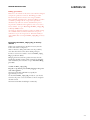
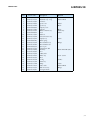
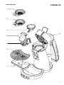
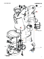
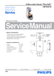
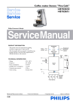
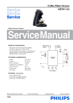
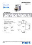
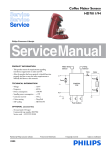
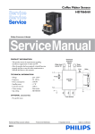
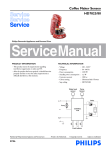
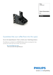
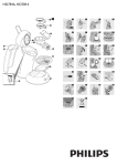
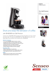
Coffee maker Senseo “Viva Café” HD7835/10 Philips Consumer Lifestyle Service Manual PRODUCT INFORMATION Display & Selection button PCB - This product meets the requirements regarding interference suppression on radio and TV. - After the product has been repaired, it should function properly and has to meet the safety requirements as officially laid down at this moment. w Interconnect PCB TECHNICAL INFORMATION - Voltage Frequency Power consumption Standby power consumption Contents water reservoir Colour setting Sap coding : : : : : : : Temp. sensor 220 - 240 V 50 - 60 Hz 1450 W 0,5 W 1200 cc Beluga HD7835/10 Brewhead detection sensor x y Water level sensor z TCO Boiler L Fuse Pump M Control PCB Coffee volume overview Min cc/mL Normal cc/mL Max cc/mL France version 80 100 140 General version 80 122 145 Fuse N Push buttons Published by Philips Consumer Lifestyle 10/05 Printed in the Netherlands © Copyright reserved Subject to modification DISASSEMBLY- AND RE-ASSEMBLY ADVISE Before you start dismantling! ! For your safety be sure the plug is disconnected from the mains! The product is designed for easy access to the internal components. Make sure that all accessories like tank, podholder, drip tray, spout and collector have been removed. To remove the back cover, follow below steps: - Remove the two Torx screws (T15) A (see exploded view). - Remove the valve outlet. - Start at the upper side of the back cover, using a flat head screwdriver to unhook the top of the back cover and gently pull the back cover from the appliance so that a little chink between back cover and brew chamber becomes visible. - Again use the screwdriver to unhook the two “snap locks” at each side of the back cover, and gently move the screwdriver in the direction of the opposite side of the appliance, in such a way that the lips of the snap locks are bent outwards and unhook. - If all snap locks are unhooked, it is possible to remove the back cover. Gently pull the back cover upwards to release the bottom part of the back cover from the housing. Please note that the back cover is still connected to the pump. - For reassembly follow these steps backwards. To remove the brew chamber lid cover, follow below steps: - Place a large screwdriver on the positions (see picture 1) and lift the cover over the snap locks on both positions, use appropriate force. HD7835/10 To remove the brew chamber head assy, follow below steps: - Remove the back cover. - Place the appliance in front of you in such a way that you are facing the rear side of the appliance. - First remove the boiler from the snap lock position of the brew chamber. - To remove the brew chamber, use your both thumbs (see picture 3) and push strongly with a little distortion (rotation) until the brew chamber comes loose (upwards). picture 3 - Reassemble follow above steps backwards. To reach the components placed inside the base (for example exchange the NTC temperature sensor) follow below steps: - First remove back cover, three-way valve and boiler. - The brew chamber can be removed by unhooking the two snap locks behind the boiler, pull the brew chamber upwards to remove it from the housing. - Remove both Torx T15 screws B (see exploded view). - Unhook the two snap locks on the back side of the base with a screwdriver (see base), the housing can now be removed. - To remove the rest of the housing unlock the last 4 snap locks on the base and gently pull of the front cover. - To reassemble follow above steps backwards. To exchange the display assembly in the brew head follow below steps: picture 1 - The cover lid can now be lifted up, but stays attached to the brew head by the push rod, to remove the complete cover including lever and push rod squeeze both legs of the push rod strongly together (see picture 2), so that the two picture 2 pins will unhook out of the hinge position on the brew chamber. - To remove lever from lid cover, take a screwdriver and bend carefully the two lips/ribs in the lid cover outwards and push the lever with force out of the hinge. - To reassemble, follow steps backwards, without using a screwdriver. - Remove the back cover, and disconnect the hose to the brew head from the three-way valve. - Dismount the water-protected interconnect-PCB on the left hand side of the appliance. - Disconnect the electrical cable of the display assy, from the interconnect PCB. - Open the brew head, use a flat head screw driver on the brew head hinge to disconnect the brew head from brew chamber. - Place the brew head upside down on a protective cloth (to prevent scratching), use two screwdrivers unhook the lid frame from the lid, both stay connected through the slider. The display assy is now accessible. - On reassembly pay special attention to the routing of the cables and hoses. OPTIONAL (accessories) - No specific issues 2-8 REPAIR INSTRUCTION HD7835/10 Note: Volume adjustment Please note after replacing the boiler the appliance has to be restored to factory default. The filling procedure (cold flush), known from the predecessor Senseo’s is no longer available after the flush before first use has been executed. When the “restore to factory default” procedure is not carried out, a new and empty boiler can be switched on, without having the protection of the initial flush procedure, causing the thermal fuses in the heating element to fail. The PCB circuit board makes it possible to adjust the volume output by means of pushing the one-cup and two-cup user controls. How to adjust the volume output: 1. Make sure the boiler is filled properly, otherwise perform fill procedure see DFU for instructions. 2. Switch appliance on and wait until the unit is ready to brew. 3. Make sure that normal cup volume has been selected with the volume selection knob (2 stripes on display, see picture) 4. Make sure a pod holder is placed, but without a Coffee POD. (Only adjusting with plain water) 5. Place a cup on the drip tray cover and push the one-cup button. 6. When the appliance has finished it is stabilized to perform the volume adjustment. 7. Empty the cup, podholder and push again for one cup setting, measure the volume output with a graduated beaker. In the table you can find the requirements for the minimum / maximum volume output cc/mL values depending from the country version: ! After a boiler re placement or drained system, carry out the “Restore boiler_empty_flag to factory default” procedure! Then the initial flush procedure can be carried out. Descaling Descaling is an important element in Senseo maintenance. It should be done at least once every 3 months, up to 6 times a Year! This will prolong the life of your appliance and will guarantee optimal brewing results for a long time. Use the correct descaling agent. Only citric acid-based descalers are suitable for descaling the SENSEO® machine. This type of descaler descales the appliance without damaging it. For the correct amount, see under ‘Descaling procedure’ below. Each descaling mixture can be used only once. After use, the descaling mixture is no longer active. We advise you to use the special SENSEO® Descaler (HD7006). Read the instructions on the package of the descaling agent. Never use a descaling agent based on mineral acids such as sulphuric acid, hydrochloric acid, sulphamic acid and acetic acid (e.g. vinegar). These descaling agents may damage your SENSEO® coffee machine. Follow the steps in the section headed “Descale the appliance” see DFU (Direction for Use manual). One-cup setting, Including Pod holder, water spec. (Without Coffee pod) Min. water cc/mL Max. water cc/mL Spanish version 51 71 France version 101 121 General version 123 143 8. Unplug the appliance from the mains. 9. Press the 1- and 2 cup button simultaneously and plug the mains on. 10. When above step succeeded the LED will turn on continuously. 11. Depending if the volume has to de- or increase you have to push the one- or two cup button. Every time you push the 1- or 2 cup button the LED will turn off for 0.5 second (feedback to user) and the pump time will be shortened or lengthened for 0.5 seconds depending which button was pushed. Pushing 1 cup button pump, time will be shorten with 0.5 sec is approximately − 3.5 cc/mL (less coffee) Pushing 2 cup button pump, time will be lengthen with 0.5 sec is approximately + 3.5 cc/mL more coffee) When the volume has to increase with 10 cc for example, push the 2 cup button 3 times. The new value will be stored when you switch the appliance off by pushing the main switch. (LED will turn off ). 12. Turn appliance on again and brew one cup, measure the volume. In case the volume is not within specification repeat steps 7 - 12. 13. End. 3-8 REPAIR INSTRUCTION HD7835/10 Filling procedure: Please note, the software of the Senseo Viva Café has changed, compared to predecessor Senseo’s! The filling procedure known from predecessor Senseo’s is no longer available. The command originally used to initiate the filling procedure (cold flush: pushing both the 1-cup and 2-cup buttons simultaneously) will now start the decalcification process. To perform a cold flush of the appliance, it has to be reset to factory default. See topic “Restoring the Boiler_empty_flag to factory default” below. As a back-up, when the appliance is in factory default setting, the cold flush will also be initiated when the user presses either the 1-cup or the 2-cup button. This functionality is only available after restoring the Boiler_empty_flag to factory default. Restoring the Boiler_empty_flag to factory default Under some circumstances it might be necessary that the boiler of the Senseo is emptied. This, for instance, during wintertime were the possibility exists that the boiler becomes frozen during transport. For those occasions it is useful to restore the Boiler_empty_ flag to production default. Bringing the Senseo back into production status, has the benefit that the flush routine will be activated automatically when installed by the consumer, see topic Automatic filling procedure. To SET the Boiler_empty_flag: Keep the 1-cup button pressed while plugging in the power cord of the appliance. The main switch LED will blink very rapidly for approximately 1 second. To check if the Boiler_empty_flag is really set, you should reconnect the power cord a second time to the net and push the main switch. The main switch LED should light continuously. 4-8 PARTS LIST HD7835/10 Pos Service code Description Remark 1 2 3 4 5 4222 259 48381 4222 259 48391 4222 247 42551 4222 259 45071 4222 259 48241 Padholder assy 1-cup Padholder assy 2-cup Collector Spout cover Spout assy Panther Black Panther Black 6 7 8 9 10 4222 240 00521 4222 247 63012 4222 259 46431 4222 240 00571 4222 247 63071 Driptray cover Driptray Water container assy Lever Pushrod 11 12 13 14 15 4222 259 45901 4222 259 45921 4222 240 01413 4222 259 48362 4222 247 06814 Selection button assy Display assy Slider spring Brew chamber assy Brew chamber seal 16 17 18 19 20 4222 240 05991 4222 247 41921 4222 259 45043 4213 247 05256 4222 259 45341 Ejector pin Distribution disk PCB assy Foot 3-Way valve 21 22 23 24 25 4222 259 44271 4222 247 06591 4222 247 05134 4222 259 47301 4222 259 37244 Boiler assy Hose O-ring NTC assy Pump V7.0 - 230 V 26 27 28 4222 247 64731 4222 259 48371 4222 247 05511 Valve outlet Back Cover assy Corrugated tube Panther Black Beluga Metal Black Black Dark Grey Metal 230 V Beluga White LED HE 230 V (NTC) 230 V 5-8 EXPLODED VIEW HD7835/10 1 2 3 8 4 5 6 7 6-8 EXPLODED VIEW HD7835/10 9 10 11 Warning: Live Voltage applied, always disconnect plug from the mains when repairing! ! 12 w C 3x 13 a 15 14 16 17 7-8 EXPLODED VIEW HD7835/10 26 x A 2x a 20 27 B 2x b 28 21 22 23 b 24 25 18 y z 18 y x z w 19 8-8