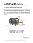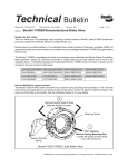
1
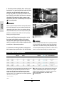
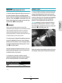
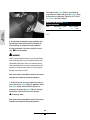
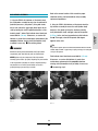
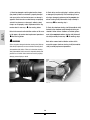
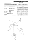
Table of Contents . . . . . . . . . . . . . . . . . . . . . . . . . . . .iii
End Fittings – Pinch Bolt Style . . . . . . . . . . . . . . . . . . .7
End Fittings – Companion Flange/Flange Yoke Style . . .9
Universal Joints . . . . . . . . . . . . . . . . . . . . . . . . . . . . . .9
Slip Member Assembly . . . . . . . . . . . . . . . . . . . . . . . .11
Lubrication . . . . . . . . . . . . . . . . . . . . . . . . . . . . . . . .13
Recommended Lubricants . . . . . . . . . . . . . . . . . . . . .15
Grease Compatibility . . . . . . . . . . . . . . . . . . . . . . . . .15
Lubrication Intervals Universal Joints . . . . . . . . . . . . .16
Lubrication Procedures Universal Joints . . . . . . . . . . .17
Lubrication Procedures Slip Member Assembly . . . . .17
Removal . . . . . . . . . . . . . . . . . . . . . . . . . . . . . . . . . .20
Removal Procedures For Aluminum Steering Shaft
(Intermediate Shaft) . . . . . . . . . . . . . . . . . . . . . . . . . .21
Removal Procedures For Universal Joints . . . . . . . . . .22
Removal Procedures For Damaged Slip Member Boot . .27
Installation . . . . . . . . . . . . . . . . . . . . . . . . . . . . . . . .30
Installation Procedures For End Fittings . . . . . . . . . . .31
Installation Procedures For Universal Joints . . . . . . .33
Installation Procedures For Slip Member Boot . . . . . .39
Installation Procedures For Aluminum Steering Shaft
(Intermediate Shaft) . . . . . . . . . . . . . . . . . . . . . . . . . .43
Glossary . . . . . . . . . . . . . . . . . . . . . . . . . . . . . . . . . .46
Appendix . . . . . . . . . . . . . . . . . . . . . . . . . . . . . . . . .48
iii
TABLE OF
CONTENTS
Inspection . . . . . . . . . . . . . . . . . . . . . . . . . . . . . . . . . .6
INSPECTION
SPICER LITE® ALUMINUM STEERING SHAFT
(INTERMEDIATE SHAFT) INSPECTION
6. NEVER stand on an aluminum steering shaft (intermediate shaft) or use it as a leverage bar. See notification decal
(reproduced below) on aluminum steering shaft (intermediate shaft).
Before You Get Started
This manual is intended to be a supplement to your original
equipment vehicle manufacturers' service manual. For
complete detailed Spicer aluminum steering shaft (interme-
NOTICE/AVISO/AVIS
diate shaft) maintenance procedures use this manual.
NO STEP
NO STEP
NO STEP
For Service and Safety requirements
see Spicer Service Manual 3264-SLSTRG or www.dana.com
NÃO PISAR
NÃO PISAR
NÃO PISAR
Para informações sobre manutençäo e exigências de seguranca
Veja o Manual de Serviços Spicer 3264-SLSTRG ou www.dana.com
NO PISAR
NO PISAR
NO PISAR
Para informaciones de mantenimiento y requisitos de seguridad
Vea el Manual de Servicios Spicer 3264-SLSTRG o www.dana.com
NE PAS APPUYER
NE PAS APPUYER
NE PAS APPUYER
Vou les exigences d’entretien et de sécurité
Dans le manuel de service Spicer n˚ 3264-SLSTRG Ou: www.dana.com
Note - Spicer Lite aluminum steering shafts (intermediate
shafts) are found on vehicles throughout the world. This
INSPECTION
manual includes international terminology. The international terms have been highlighted in teal.
Caution - Under no circumstances should an individual
attempt to perform aluminum steering shaft (intermediate
shaft) service and/or maintenance procedures for which
he or she has not been trained or does not have the
proper tools and equipment. w See warning, below.
7. NEVER make any modifications to an aluminum steering shaft (intermediate shaft) that were not original to the
design of the product.
W WARNING
Failure to take common-sense, precautionary measures when
working on a vehicle could result in property damage, personal
injury or death. In order to avoid property damage, personal
injury or death, you must:
8. NEVER USE an aluminum steering shaft (intermediate
shaft) in non-power steering applications.
w See warning, below.
1. ALWAYS wear safety glasses when performing mainte-
Spicer Lite aluminum steering shafts (intermediate shafts) are to
be used only in original equipment vehicle manufacturers’ applications. Failure to do so can result in impaired steering and
possible loss of vehicle control, which can result in property
damage, personal injury or death.
W WARNING
nance or service. Failure to wear safety glasses could
result in personal injury, partial or complete vision loss.
2. NEVER attempt to remove an aluminum steering shaft
(intermediate shaft) from a vehicle while the engine is
running. Be sure that the vehicle’s engine is off, and keys
are removed from ignition.
9. NEVER use an aluminum steering shaft (intermediate
shaft) in a cab over application. w See warning, above.
10. NEVER use an aluminum steering shaft (intermediate
shaft) in a power-take-off (PTO) application.
3. NEVER go under or work on a vehicle that is not on a
level or flat surface.
11. NEVER high-pressure wash aluminum steering shaft
(intermediate shaft) u-joints or booted slip member with
degreasing solvent or water.
4. NEVER remove an aluminum steering shaft (intermediate shaft) without blocking the vehicle’s wheels.
12. NEVER replace only one component of the slip member assembly (yoke shaft or slip yoke).
5. NEVER heat an aluminum steering shaft (intermediate
shaft) component or use a hammer on the aluminum components of the steering shaft to remove it from the vehicle.
6
1. Check all input and output end fittings for looseness in
the spline connection. Grasp the end fitting with both
hands. Try to move it vertically and horizontally to feel
any looseness. (See photo 2 below.) There should NOT
be any movement in the end fittings relative to the input
or output shaft to which they are connected.
w See warning, below.
Spicer Lite aluminum steering shafts (intermediate shafts)
should be carefully inspected at recommended original
equipment vehicle manufacturers’ service intervals
and/or at Spicer recommended lubrication intervals, as
shown in table A, below. Be sure to follow ALL inspection
procedures described in this manual.
W WARNING
Note - The following procedures are to be performed
prior to any lubrication of the universal joints. The addi-
Failure to replace damaged aluminum steering shaft (intermediate shaft) components can cause aluminum steering shaft
(intermediate shaft) failure. Failure of an aluminum steering
shaft (intermediate shaft) can result in impaired steering and
possible loss of vehicle control, which can result in property
damage, personal injury or death.
tion of lubricant can mask the looseness in a component
that is beginning to show wear and may be in need of
replacement.
Required Tool
• Spicer Steering Wear Indicator
Part Number STWI-2 (See photo 1)
1-800-826-HELP (U.S. only)
(For proper tool usage instruction – refer to Appendix A.)
If looseness is evident, replacement of the end fitting is
necessary. For proper end fitting replacement procedures, refer to the removal and installation sections of
this manual.
Photo 2
Photo 1
UNIVERSAL JOINT MAXIMUM LUBRICATION INTERVALS
SERIES
SPL 6 (relubeable style)
CITY
ON-HWY.
LINEHAUL
OFF-HWY.
25,000 Mi.
50,000 Mi.
50,000 Mi.
25,000 Mi.
40,000 Km
80,000 Km
80,000 Km
40,000 Km
or
or
or
or
3 Months
6 Months
6 Months
3 Months
(whichever comes first)
(whichever comes first)
(whichever comes first)
(whichever comes first)
Linehaul is defined as 100% of operation time on smooth
concrete or asphalt.
Off-highway is defined as all applications requiring more than
10% of operating time on gravel, dirt or unpaved roads.
City is defined as all applications that require a minimum of 90%
of operation time within city limits.
On-highway is defined as all applications requiring less than
10% of operating time on gravel, dirt or unpaved roads.
Table A
7
END FITTING
INSPECTION
END FITTINGS
PINCH BOLT STYLE
ALUMINUM STEERING SHAFT
(INTERMEDIATE SHAFT) INSPECTION PROCEDURES
2. Visually inspect both end fittings of the steering shaft
for looseness or a gap at the pinch bolts and/or nuts. Also
check to be sure the pinch bolts and/or nuts are not
missing. (See photo 3.) If any of these situations are evident, inspect the male splined shaft for wear or damage.
(See photo 4.) If the male shaft splines are worn or damaged, both the male shaft and end fitting must be replaced.
w See warning, below.
pinch bolt
no gap
forging width
nut
no gap
END FITTING
INSPECTION
W WARNING
Photo 3
Failure to replace damaged aluminum steering shaft (intermediate shaft) components can cause aluminum steering shaft
(intermediate shaft) failure. Failure of an aluminum steering
shaft (intermediate shaft) can result in impaired steering and
possible loss of vehicle control, which can result in property
damage, personal injury or death.
For proper end fitting replacement procedures, refer to
the removal and installation sections of this manual.
For proper male splined shaft replacement procedures,
replace in accordance with the original equipment vehicle
manufacturers’ replacement procedures.
Photo 4
W WARNING
Failure to torque pinch bolts and/or nuts to required specifications
can result in failure of the aluminum steering shaft (intermediate
shaft). Failure of an aluminum steering shaft (intermediate shaft)
3. If no looseness or damage is evident, re-torque pinch
bolts to proper torque specifications. (See table B, below.)
can result in impaired steering and possible loss of vehicle control,
which can result in property damage, personal injury or death.
PINCH BOLT* AND/OR NUT TORQUE SPECIFICATIONS
KIT #
BOLT
BOLT LENGTH
WRENCH SIZE
FOR BOLT
FOR NUT
NUT
WRENCH SIZE
BOLT HOLE
DRY TORQUE
FOR END YOKE WITH
DIAMETER
NM
FT.LB.
FORGING WIDTH OF***
211269X
included
2"
9/16"
included
9/16"
3/8"
30-35
40-48
1.500"
211270X
included
1.75"
9/16"
included
9/16"
3/8"
30-35
40-48
1.125" & 1.25"
211271X
included
2"
5/8"
included
11/16"
7/16"
46-55
63-75
1.500"
211272X
included
1.75"
5/8"
included
11/16"
7/16"
46-55
63-75
1.125" & 1.25"
211273X
included*†
1.25"
5/8"
not required
–
7/16" thread dia.
46-55
63-75
1.125" w/threads in yoke
211274X
included
2.125"
5/8"
included
11/16"
7/16"
46-55
63-75
1.620"
*Aluminum steering shaft (intermediate shaft) end fitting pinch bolts
are to be S.A.E. grade eight. Nuts for pinch bolts are to be selflocking with a full nylon insert, serrated washer seat or upset
threads. An S.A.E. grade five hex nut used in conjunction with a
split lock washer is also acceptable. Do not use inferior grade bolts.
Note - When specified, use the original equipment vehicular manufacturers’ recommended pinch bolts and/or nuts. If no original
equipment vehicle manufacturers’ specification is given, use the
Spicer recommended hardware. (See table B, above.)
See warning, above.
w
*†Bolt must have self-locking feature.
***See photo 3, above
Table B
8
UNIVERSAL JOINTS
END FITTINGS
COMPANION FLANGE/FLANGE YOKE STYLE
steering shaft (intermediate shaft), check for excessive
the spline connection. Grasp the end fitting with both
circumferential (backlash) looseness of the universal joint
hands. Try to move it vertically and horizontally to feel any
across the yoke lug ear span. (See photo 5 and Appendix.)
looseness. There should NOT be any movement in the end
Try to rotate the shaft back and forth to indicate any
fittings relative to the input or output shaft to which they
looseness. There should never be more than .011 in.
are connected.
(.28 mm) movement in the universal joint kit relative to
w See warning, below.
W WARNING
the inboard and outboard yokes. If looseness is greater
Failure to replace damaged aluminum steering shaft
necessary.
than stated above, replacement of the universal joint kit is
(intermediate shaft) components can cause aluminum steering
w See warning, step 1, left.
shaft (intermediate shaft) failure. Failure of an aluminum
steering shaft (intermediate shaft) can result in impaired
steering and possible loss of vehicle control, which can result
in property damage, personal injury or death.
2. Visually inspect all companion flange/flange yoke bolts
and nuts (if applicable) for looseness, wear or damage.
If bolts or nuts have looseness, wear or damage, replacement of the companion flange and flange yoke is necessary. w See warning, above.
Photo 5
For proper replacement procedures for bolts, nuts, com-
Refer to the removal and installation sections of this man-
panion flange and flange yoke, refer to the removal and
ual for proper universal joint kit replacement procedures.
installation sections of this manual.
3. If no looseness or damage is evident, re-torque
companion flange/flange yoke bolts and nuts (if applicable) to required specifications. (See table C, below.)
COMPANION FLANGE/FLANGE YOKE BOLT
AND NUT TORQUE SPECIFICATIONS
WRENCH
SIZE
1/2"
DRY TORQUE
NM
FT. LB.
22-26
30-35
Table C
9
UNIVERSAL JOINT
INSPECTION
1. Using the STWI-2 dial indicator, mounted to aluminum
1. Check all input and output end fittings for looseness in
4. If the grease zerk (nipple) fitting is loose, tighten to
snug. Continue to tighten until grease zerk (nipple) fitting
is oriented for easy lubrication. Tighten to (31-55 in. lbs.)
(1.9-3.4 Nm). (See table D, below.)
UNIVERSAL JOINT GREASE ZERK (NIPPLE)
FITTING SPECIFICATIONS500 .375
SERIES
SPL6
snap ring
UNIVERSAL JOINT
INSPECTION
Table D
Photo 6
2. Visually check for damaged, severely corroded, or missing snap rings in both universal joint kits. (See photo 6.)
If any snap rings are damaged, severely corroded or
missing, replacement of the universal joint kit is necessary.
w See warning, below.
W WARNING
Failure to replace damaged aluminum steering shaft (intermediate shaft) components can cause aluminum steering shaft
(intermediate shaft) failure. Failure of an aluminum steering
shaft (intermediate shaft) can result in impaired steering and
possible loss of vehicle control, which can result in property
damage, personal injury or death.
Refer to the removal and installation sections of this manual
for proper universal joint kit replacement procedures.
3. Visually inspect all the universal joint kits for the presence of grease zerk (nipple) fittings (if applicable). Grease
zerk (nipple) fittings should not be missing, loose or
fractured. If the grease zerk (nipple) fitting is missing or
fractured, the universal joint kit must be replaced.
w See warning, above.
Refer to the removal and installation sections of this manual
for proper universal joint kit replacement procedures.
10
GREASE ZERK (NIPPLE) FITTING
ZERK (NIPPLE) TORQUE
P/N
NM
500175-2
1.9-3.4
IN.LB.
31-55
Refer to the removal section of this manual for proper
SLIP MEMBER ASSEMBLY
aluminum steering shaft (intermediate shaft) assembly
replacement procedures.
1. Using the STWI-2 dial indicator, as illustrated, check
(backlash) looseness. (See photo 7.) Using both hands,
2. Using the STWI-2 dial indicator, as illustrated, check the
one on each side of the gage, apply direct torque to the
slip member assembly for excessive radial (broken back)
shaft by twisting the shaft in opposite directions as illus-
looseness. (See photo 8.) Grasp the aluminum steering
trated in photo 7, below. Total indicator travel should not
shaft (intermediate shaft) and apply a load of five pounds
exceed .040 in. (1.0 mm). If looseness, as read on dial
(2.27 kgs.) to the shaft and perpendicular to dial indicator
indicator, is greater than stated above, replacement of the
face. T Then apply a load of five pounds 180 degrees
complete aluminum steering shaft (intermediate shaft)
opposite to the shaft.
assembly is necessary.
w See warning, below.
T
W WARNING
Tip
Loop a wire or plastic zip tie around the shaft, between the boot and the
smaller clamp of STWI – 2 gage. Using a spring scale (e.g. fish scale) pull
on loop to five pounds.
Aluminum steering shaft (intermediate shaft) slip member
components (yoke shaft and slip yoke) are matched sets.
NEVER replace only one component of the slip member
Total indicator travel should not exceed .060 in. (1.5 mm).
assembly (yoke shaft or slip yoke). Replacing only one member
If looseness, as read on dial indicator, is greater than
of the slip member assembly can result in impaired steering
stated above, replacement of the complete aluminum
and possible loss of vehicle control which can result in
steering shaft (intermediate shaft) assembly is necessary.
w See warning, step 1.
property damage, personal injury or death.
Photo 7
Photo 8
11
SLIP MEMBER
INSPECTION
the slip member assembly for excessive circumferential
3. Check for damaged or missing boot and/or clamps.
4. Check to be sure the welch plug is not loose, missing
(See photo 9.) Make sure the boot is properly clamped
or damaged. (See photo 10.) If the welch plug is loose,
and square to the shaft and no looseness or damage is
missing or damaged, replacement of the complete alu-
apparent. Check to make sure boot clamps are properly
minum steering shaft (intermediate shaft) assembly is
necessary. w See warning, step 3.
seated. If any looseness or damage is evident or boot
clamps are not properly seated, replacement of the slip
member boot is necessary.
w See warning, below.
5. Check the aluminum steering shaft (intermediate shaft)
for dents in the aluminum and for damage to the lug ear
SLIP MEMBER
INSPECTION
Refer to the removal and installation sections of this man-
shoulder. If either of these situations are evident, replace-
ual for proper slip member boot replacement procedures.
ment of the complete aluminum steering shaft (intermedi-
w See warning, below.
ate shaft) assembly is necessary.
w See warning, step 3.
W WARNING
Refer to the removal and installation sections of this
Failure to replace damaged aluminum steering shaft (interme-
manual for proper aluminum steering shaft (intermediate
diate shaft) components can cause aluminum steering shaft
shaft) assembly replacement procedures.
(intermediate shaft) failure. Failure of an aluminum steering
shaft (intermediate shaft) can result in impaired steering and
possible loss of vehicle control, which can result in property
damage, personal injury or death.
welch plug
Photo 9
Photo 10
12