1
MICROWAVE OVEN
CE745GR
SERVICE
Manual
CONTENTS
MICROWAVE OVEN
1. Precaution
2. Specifications
3. Operating Instructions
4. Disassembly and Reassembly
5. Alignment and Adjustments
Auto
l b s.
kg
Auto
oz.
g
1-2-3
h
10min
min
1min
10s.
6. Troubleshooting
1min+
GRILL
CE745GR
7. Exploded Views and Parts List
8. PCB Diagrams
9. Schematic Diagrams
BWT
PRECAUTIONS TO BE OBSERVED BEFORE AND DURING SERVICING TO
AVOID POSSIBLE EXPOSURE TO EXCESSIVE MICROWAVE ENERGY
(a) Do not operate or allow the oven to be operated
with the door open.
(b) Make the following safety checks on all ovens
to be serviced before activating the magnetron
or other microwave source, and make repairs as
necessary:
(1) Interlock operation,
(2) proper door closing,
(3) seal and sealing surfaces (arcing, wear, and
other damage),
(4) damage to or loosening of hinges and latches,
(5) evidence of dropping or abuse.
(c) Before turning on microwave power for any
service test or inspection within the microwave
generating compartments, check the magnetron,
wave guide or transmission line, and cavity for
proper alignment, integrity, and connections.
(d) Any defective or misadjusted components in
the interlock, monitor, door seal, and
microwave generation and transmission
systems shall be repaired, replaced, or adjusted
by procedures described in this manual before
the oven is released to the owner.
(e) A Microwave leakage check to verify
compliance with the Federal performance
standard should be performed on each oven
prior to release to the owner.
Samsung Electronics
1. Precaution
Follow these special safety precautions. Although the microwave oven is completely safe during ordinary
use, repair work can be extremely hazardous due to possible exposure to microwave radiation, as well as
potentially lethal high voltages and currents.
1-1 Safety precautions (
)
1. All repairs should be done in accordance
with the procedures described in this
manual. This product complies with
Federal Performance Standard 21 CFR
Subchapter J (DHHS).
2. Pacemaker wearers must consult a physician
before attempting to service an MWO.
8. Notify the Central Service Center if the
microwave leakage exceeds 5 mw/cm2
4. Check all grounds.
5. Do not power the MWO from a "2-prong"
AC cord. Be sure that all of the built-in
protective devices are replaced. Restore any
missing protective shields.
6. When reinstalling the chassis and its
assemblies, be sure to restore all protective
devices, including: nonmetallic control
knobs and compartment covers.
7. Make sure that there are no cabinet openings
through which people--particularly
children--might insert objects and contact
dangerous voltages. Examples: Lamp hole,
ventilation slots.
8. In the event of suspected microwave energy
leakage in excess of 5mW/§†, please notify
J.V.SAMSUNG SERVICE LTD.
MARSHAL ZHUKOU.,1.OFFICE 201
123308,MOSCOW,RUSSIA
9. Service technicians should remove their
watches while repairing an MWO.
10. To avoid any possible radiation hazard,
replace parts in accordance with the wiring
diagram. Also, use only the exact
replacements for the following parts:
Primary and secondary interlock switches,
interlock monitor switch.
Samsung Electronics
11. If the fuse is blown by the Interlock Monitor
Switch: Replace all of the following at the
same time: Primary and secondary switches,
as well as the Interlock Monitor Switch. The
correct adjustment of these switches is
described elsewhere in this manual. Make
sure that the fuse has the correct rating for
the particular model being repaired.
12. Design Alteration Warning:
Use exact replacement parts only, i.e.,
only those that are specified in the
drawings and parts lists of this manual.
This is especially important for the
Interlock switches, described above.
Never alter or add to the mechanical or
electrical design of the MWO. Any design
changes or additions will void the
manufacturer's warranty.10.Always unplug
the unit's AC power cord from the AC
power source before attempting to
remove or reinstall any component or
assembly.
13. Never defeat any of the B+ voltage
interlocks. Do not apply AC power to the
unit (or any of its assemblies) unless all
solid-state heat sinks are correctly installed.
14. Some semiconductor ("solid state") devices
are easily damaged by static electricity. Such
components are called Electrostatically
Sensitive Devices (ESDs). Examples include
integrated circuits and field-effect
transistors.
Immediately before handling any
semiconductor components or assemblies,
drain the electrostatic charge from your
body by touching a known earth ground.
15. Always connect a test instrument's ground
lead to the instrument chassis ground before
connecting the positive lead; always remove
the instrument's ground lead last.
1-1
Pretaution
1-2 Special Servicing Precautions (Continued)
16. When checking the continuity of the witches
or transformer, always make sure that the
power is OFF, and one of the lead wires is
disconnected.
17. Components that are critical for safety are
indicated in the circuit diagram by
shading,
or
.
18. Use replacement components that have the
same ratings, especially for flame resistance
and dielectric strength specifications. A
replacement part that does not have the
same safety characteristics as the original
might create shock, fire or other hazards.
1-3 Special High Voltage Precautions
1. High Voltage Warning
Do not attempt to measureany of the high
voltages--this includes the filament voltage
of the magnetron. High voltage is present
during any cook cycle.
Before touching any components or wiring,
always unplug the oven and discharge the
high voltage capacitor (See Figure 1-1)
2. The high-voltage capacitor remains charged
about 30 seconds after disconnection. Short
the negative terminal of the high-voltage
capacitor to the oven chassis. (Use a
screwdriver.)
3. High voltage is maintained within specified
limits by close-tolerance, safety-related
components and adjustments. If the high
voltage exceeds the specified limits, check
each of the special components.
Fig. 1-1. Discharging the High Voltage Capacitor
1-2
Samsung Electronics
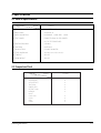
2. Specifications
2-1 Table of Specifications
MODEL
ITEM
CE745GR
TIMER
99 MINUTES 90 SECONDS
POWER SOURCE
230V/50HZ, AC
POWER CONSUMPTION
MICROWAVE : 1,400W,GRILL : 1100W
OUTPUT POWER
FROM85 TO 850W (10 LEVEL POWER)
(IEC-705 TEST PROCEDURE)
OPERATING FREQUENCY
2,450MHz
MAGNETRON
OM75PH(31)
COOLING METHOD
COOLING FAN MOTOR
OUTSIDE DIMENSIONS
191/4"(W) x 1027/32"(H) x 143/8"(D)
NET WEIGHT
36.3 LBS.
SHIPPING WEIGHT
39.6 LBS.
2-2 Comparison Chart
MODEL
FEATURE
MORE/LESS
AUTO REHEAT
AUTO DEFROST
TIME COOK
POWER LEVEL
INSTANT COOK
MEMORY
BOOST
CHILD LOCK
CLOCK
GRILL
COMBI
Samsung Electronics
CE745GR
O
O
O
O
O
O
O
O
O
O
O
2-1
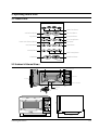
3. Operating Instructions
3-1 Control Panel
Instant Cook Button
Auto Defrost Butten
Auto
Auto Cook Button
Auto
Kg,g Button
More/Less Button
oz.
g
lbs.
kg
Clock Setting Button
Power Level Selection Button
Grill Button
Hold/Timer Button
Combi Button
1-2-3
h
10min
Memory Button
min
1min
10s.
Timer Setting Button
Stop Button
Start/Boost Button
1min+
CE745GR
3-2 Features & External Views
Ventilation Slot
Door
Door Latches
Light
,,,,,,,,,,,,,,,,,
,,,,,,,,,,,,,,,,,
,,,,,,,,,,,,,,,,,
,,,,,,,,,,,,,,,,,
,,,,,,,,,,,,,,,,,
,,,,,,,,,,,,,,,,,
,,,,,,,,,,,,,,,,,
,,,,,,,,,,,,,,,,,
,,,,,,,,,,,,,,,,,
,,,,,,,,,,,,,,,,,
,,,,,,,,,,,,,,,,,
,,,,,,,,,,,,,,,,,
,,,,,,,,,,,,,,,,,
,,,,,,,,,,,,,,,,,
,,,,,,,,,,,,,,,,,
,,,,,,,,,,,,,,,,,
,,,,,,,,,,,,,,,,,
,,,,,,,,,,,,,,,,,
,,,,,,,,,,,,,,,,,
,,,,,,,,,,,,,,,,,
,,,,,,,,,,,,,,,,,
,,,,,,,,,,,,,,,,,
,,,,,,,,,,,,,,,,,
,,,,,,,,,,,,,,,,,
,,,,,,,,,,,,,,,,,
,,,,,,,,,,,,,,,,,
,,,,,,,,,,,,,,,,,
,,,,,,,,,,,,,,,,,
,,,,,,,,,,,,,,,,,
,,,,,,,,,,,,,,,,,
,,,,,,,,,,,,,,,,,
,,,,,,,,,,,,,,,,,
,,,,,,,,,,,,,,,,,
,,,,,,,,,,,,,,,,,
,,,,,,,,,,,,,,,,,
,,,,,,,,,,,,,,,,,
,,,,,,,,,,,,,,,,,
,,,,,,,,,,,,,,,,,
,,,,,,,,,,,,,,,,,
Safety Interlock Holes
Auto
lbs.
kg
Auto
Control Panel
oz.
g
1-2-3
h
10min
min
1min
10s.
1min+
CE745GR
Open Door Push Button
Glass Plate
Guide Roller
Auto
l b s.
kg
275mm
GRILL WIRE RACK
Auto
oz.
g
1-2-3
h
10min
min
1min
10s.
1min+
GRILL
CE745GR
200mm
357mm
489mm
Samsung Electronics
365mm
3-1
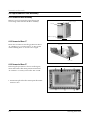
4. Disassembly and Reassembly
4-1 Replacement of Magnetron, Motor Assembly and Lamp
Remove the magnetron including the shield case,
permanent magnet, choke coils and 500pF
capacitors (all of which are contained in one
assembly).
Cover Air
Lamp
Thermo S/W
1. Disconnect all lead wires from the magnetron
Fan Motor
and lamp.
BKT-Mountain
2. Remove the bracket mounting.
3. Remove the air cover.
4. Remove screws securing the magnetron to the
wave guide.
5. Take out the magnetron very carefully.
6. Remove screws from the back panel.
7.Remove the assy noise filter.
8. Take out the fan motor.
9. Remove the oven lamp by pulling out from hole
of air cover carefully.
Screw
H. V. Trans
Magnetron
10. NOTE1: When removing the magnetron, make
H. V. Capacitor
sure that its antenna does not hit any
adjacent parts, or it may be damaged.
11. NOTE2: When replacing the magnetron, be
sure to remount the magnetron gasket
in the correct position and make sure
the gasket is in good condition.
4-2 Replacement of High Voltage Transformer
1. Discharge the high voltage capacitor.
2. Disconnect all the leads.
3. Remove the mounting bolts.
4. Reconnect the leads correctly and firmly.
PRECAUTION
Servicemen should remov their watches whenever
working close to or replacing the magnetron.
PRECAUTION
There exists HIGH VOLTAGE ELECTRICITY with high
current capabilities in the circuits of the HIGH
VOLTAGE TRANSFORMER secondary and filament
terminals. It is extremely dangerous to work on or
near these circuits with the oven energized.
DO NOT measure the voltage in the high voltage
circuit including filament voltage of magnetron.
Samsung Electronics
Bolts
H. V. Trans
4-1
Disassembly and Reassembly
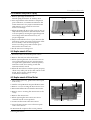
4-3 Replacement of Door Assembly
4-3-1 Removal of Door Assembly
Remove screws securing the upper hinge and
lower hinge. Then remove the door assembly.
Upper Hinge
Screw
Lower Hinge
Screw
4-3-2 Removal of Door "C"
Insert flat screwdriver into the gap between Door
"A" and Door "C" to remove Door "C". Be careful
when handling Door "C" because it is fragile.
Door "C"
Door "A"
4-3-3 Removal of Door "E"
Following the procedure as shown in the figure,
insert and bend a thin metal plate between Door
"E" and Door "A" until you hear the 'tick' sound.
Door "E"
1. Insertion depth of the thin metal plate should be
0.5mm or less.
4-2
Samsung Electronics
Disassembly and Reassembly
4-3-4 Removal of Key Door & Spring
1. Remove pin hinge from Door "E"
Detach spring from Door "E" and key door.
Door "E"
2. After replacement of the defective component
parts of the door, reassemble it and follow the
instructions below for proper installation and
adjustment so as to prevent an excessive
microwave leakage.
3. When mounting the door to the oven, be sure to
adjust the door parallel to the bottom line of the
oven face plate by moving the upper hinge and
lower hinge in the direction necessary for
proper alignment.
Key Door
Spring
4. Adjust so that the door has no play between the
inner door surface and oven front surface. If the
door assembly is not mounted properly,
microwave energy may leak from the space
between the door and oven.
5. Do the microwave leakage test.
4-4 Replacement of Fuse
1. Disconnect the oven from the power source.
2. Remove the 10A fuse in the Noise filter.
3. When replacing the 10A fuse, be sure to use an
exact replacement part. If new 10A fuse blows
out again after replacement, check the primary
interlock switch, door sensing switch and
interlock monitor switch.
4. When the above three switches operate properly,
check if any other part such as the control circuit
board, blower motor or high voltage
transformer is defective.
4-5 Replacement of Drive Motor
1. Take out the glass tray, guide roller and coupler
from cavity.
2. Turn the oven upside down to replace the drive motor.
Drive Motor
Screw
3. Remove a screw securing the drive motor cover.
4. Disconnect all the lead wires from the drive motor.
5. Remove screws securing the drive motor to the
cavity.
Thermo
Switch
6. Remove the drive motor.
7. When replacing the drive motor, be sure to
remount it in the correct position.
8. Connect all the leads to the drive motor.
Drive Motor Cover
Base Plate
9. Screw the deive motor cover to the base plate
with a screw driver.
10. Remount the coupler in the correct position.
Samsung Electronics
4-3
Disassembly and Reassembly
4-6 Replacement of Control Circuit Board
4-6-1 Removal of Control Box Assembly
1. Be sure to ground any static electric charge in
your body and never touch the control circuit.
2. Disconnect the connectors from the control
circuit board.
Screw
3. Remove screws securing the control box
assembly.
4. Remove the screw securing the ground tail of
the keyboard.
Control Box
4-6-2 Removal of P.C.B Assembly
1. Pull the lever end of the plastic fastener and
remove the Flexible Printed Circuit(FPC) of
membrane panel.
2. Remove screws securing the control circuit
board.
FPC Connector
Screw
3. Lift up the control circuit board from the Ass'y
control box.
4. When reconnecting the FPC connector, make
sure that the holes on the connector are properly
engaged with the hooks on the Plastic Fastener.
4-6-3 Removal of Window Display & Membrane Panel
1. Window display should not be disassembled as
its mounting tabs will be broken. If repair work
is difficult, replace with Ass'y control panel.
2. The membrane key board is attached to the
escutcheon base with doublefaced adhesive
tape. Therefore, applying hot air such as using
of hair dryer is recommended for smoother
removal.
3. When installing new membrane key board,
make sure that the surface of escutcheon base is
cleaned sufficiently so that any problems
(shorted contacts or uneven surface) can be
avoided.
4-4
Window
Display
Membrane
Panel
Samsung Electronics
5. Alignment and Adjustments
PRECAUTION
1. High voltage is present at the high voltage terminals during any cook cycle.
2. It is neither necessary nor advisable to attempt measurement of the high voltage.
3. Before touching any oven components or wiring, always unplug the oven from its power source and discharge the high voltage
capacitor.
5-1 High Voltage Transformer
1. Remove connectors from the transformer terminals
and check continuity.
2. Normal resistance readings are as follows:
MODEL
Secondary
Filament
Primary
Filament Terminals
CE745GR
103.2Ω ¡ 10%
Shows Continuity
1.61Ω ¡ 10%
(Room temperature = 20ûC)
Primary
Terminals
5-2 Low Voltage Transformer
1. The low voltage transformer is located on the
control circuit board.
2. Remove the low voltage transformer from the
PCB Ass'y and check continuity.
3. Normal resistor reading is shown in the table.
Terminals
1~2(Input)
4~5(Output17V)
7~8(Output2.9V)
Resistance
1149Ω
12.26Ω
2.574Ω
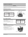
5-3 Magnetron
1. Continuity checks can indicate only an open
filament or a shorted magnetron. To diagnose an
open filament or shorted magnetron :
2. Isolate the magnetron from the circuit by
disconnecting its leads.
3. A continuity check across the magnetron filament
terminals should indicate one ohm or less.
4. A continuity check between each filament terminal
and magnetron case should read open.
Magnetron Antenna
Gasket Plate
Cooling Fins
Samsung Electronics
5-1
Alignment and Adjustments
5-4 High Voltage Capacitor
1. Check continuity of the capacitor with the meter set at the highest resistance scale.
2. Once the capacitor is charged, a normal capacitor shows continuity for a short time, and then indicates 9MΩ.
3. A shorted capacitor will show continuous continuity.
4. An open capacitor will show constant 9MΩ.
5. Resistance between each terminal and chassis should read infinite.
5-5 High Voltage Diode
1. Isolate the diode from the circuit by disconnecting its leads.
2. With the ohm-meter set at the highest resistance scale, measure across the diode terminals. Reverse the
meter leads and read the resistance. A meter with 6V, 9V or higher voltage batteries should be used to
check the front-to back resistance of the diode (otherwise an infinite resistance may be read in both
directions). The resistance of a normal diode will be infinite in one direction and several hundred KΩ in
the other direction.
5-6 Main Relay and Power Control Relay
1. The relays are located on the PCB Ass'y. Isolate them from the main circuit by disconnecting the leads.
2. Operate the microwave oven with a water load in the oven. Set the power level set to high.
3. Check continuity between terminals of the relays after the start pad is pressed.
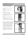
5-7 Adjustment of Primary Switch, Door Sensing Switch and Monitor Switch
Precaution
For continued protection against radiation hazard, replace parts in accordance with the wiring diagram and be sure to use the
correct part number for the following switches: Primary and door sensing switches, and the interlock monitor switch (replace all
together). Then follow the adjustment procedures below. After repair and adjustment, be sure to check the continuity of all
interlock switches and the interlock monitor switch.
1. When mounting Primary switch and Interlock
Monitor switch to Latch Body, consult the
figure.
Primary Interlock Switch
2. No specific adjustment during installation of
Primary switch and Monitor switch to the latch
body is necessary.
3. When mounting the Latch Body to the oven
assembly, adjust the Latch Body by moving it so
that the oven door will not have any play in it.
Check for play in the door by pulling the door
assembly. Make sure that the latch keys move
smoothly after adjustment is completed.
Completely tighten the screws holding the Latch
Body to the oven assembly.
4. Reconnect to Monitor switch and check the
continuity of the monitor circuit and all latch
switches again by following the components test
procedures.
5. Confirm that the gap between the switch
housing and the switch actuator is no more than
0.5mm when door is closed.
5-2
Interlock Monitor
Switch
Lever Door
Body Latch
Primary switch
Monitor switch (COM-NC)
Door Sensing S/W
Door Sensing
Switch
Door Open
Door Closed
∞
0
∞
0
∞
0
Samsung Electronics
Alignment and Adjustments
5-8 Output Power of Magnetron
CAUTION
MICROWAVE RADIATION
PERSONNEL SHOULD NOT ALLOW EXPOSURE TO MICROWAVE RADIATION FROM MICROWAVE GENERATOR OR OTHER PARTS
CONDUCTING MICROWAVE ENERGY.
The output power of the magnetron can be measured by performing a water temperature rise test.
Equipment needed :
* Two 1-liter cylindrical borosilicate glass vessel (Outside diameter 190 mm)
* One glass thermometer with mercury column
NOTE: Check line voltage under load. Low voltage will lower the magnetron output. Make all temperature
and time tests with accurate equipment.
1. Fill the one liter glass vessel with water.
2. Stir water in glass vessel with thermometer, and record glass vessel's temperature ("T1", 10±1ûC).
3. After moving the water into another glass vessel, place it in the center of the cooking tray. Set the oven to high
power and operate for 51seconds exactly. (2 seconds included as a holding time of magnetron oscillation:)
4. When heating is finished, stir the water again with the thermometer and measure the temperature ("T2").
5. Subtract T1 from T2. This will give you the water temperature rise. (∆T)
6. The output power is obtained by the following formula;
Output Power =
4.187 x 1000 x ∆T+0.88xMcx(T2-T0)
49.25
49.25: Heating Time (sec)
4.187 : Coefficient for Water
1000 : Water (cc)
∆T : Temperature Rise (T2-T1)
Mc : Cylindrical borosilicate glass weight
To : Room temperature.
7. Normal temperature rise for this model is 9ûC to 11ûC at 'HIGH'.
NOTE 1: Variations or errors in the test procedure will cause a variance in the temperature rise.
Additional power test should be made if temperature rise is marginal.
NOTE 2: Output power in watts is computed by multiplying the temperature rise (step 5) by a factor of 85
times the of centigrade temperature.
5 9 Leakage Measuring Procedure
5-9-1 Record keeping and notification after measurement
1) After adjustment and repair of a radiarion
preventing device, make a repair record for the
measured values, and keep the data.
2) If the radiation leakage is more than 5 mW/§† after
determining that all parts are in good condition,
functioning properly and the identical parts are
replaced as listed in this manual notift that fact to ;
J.V.SAMSUNG SERVICE LTD.
MARSHAL ZHUKOU.,1.OFFICE 201
123308,MOSCOW,RUSSIA
5-9-2 At least once a year have the microwave energy
survey meter checked for accuracy by its
manufacturer.
Samsung Electronics
5-3
Alignment and Adjustments
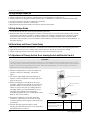
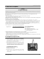
5-10 Microwave Heat Distribution - Heat Evenness
The microwave heat distribution can be checked indirectly by measuring the water temperature rise at
certain positions in the oven:
1. Prepare five beakers made of 'Pyrex', having 100 milliliters capacity each.
2. Measure exactly 100milliliters off water load with a measuring cylinder, and pour into each beaker.
3. Measure the temperature of each water load. (Readings shall be taken to the first place of decimals.)
4. Put each beaker in place on the cooking tray as illustrated in figure below. Start heating.
5. After heating for 2 minutes, measure the water temperature in each beaker.
6. Microwave heat distribution rate can be calculated as follows:
Heat Distribution =
Minimum
Temperature Rise
Maximum
Temperature Rise
D
X 100(%)
Beaker
D
The result should exceed 65%.
D/4
D/4
D/4
D/4
5-4
Cooking Tray
Samsung Electronics
6. Troubleshooting
PRECAUTION
1. CHECK GROUNDING BEFORE CHECKING FOR TROUBLE.
2. BE CAREFUL OF THE HIGH VOLTAGE CIRCUIT.
3. DISCHARGE THE HIGH VOLTAGE CAPACITOR.
4. WHEN CHECKING THE CONTINUITY OF THE SWITCHES OR TRANSFORMER, DISCONNECT ONE LEAD WIRE FROM THESE
PARTS AND THEN CHECK CONTINUITY WITHOUT THE POWER SOURCE ON. TO DO OTHERWISE MAY RESULT IN A FALSE
READING OR DAMAGE TO YOUR METER.
5. DO NOT TOUCH ANY PART OF THE CIRCUIT OR THE CONTROL CIRCUIT BOARD, SINCE STATIC DISCHARGE MAY DAMAGE IT.
ALWAYS TOUCH GROUND WHILE WORKING ON IT TO DISCHARGE ANY STATIC CHARGE BUILT UP.
6-1 Electrical Malfunction
SYMPTOM
CAUSE
CORRECTIONS
Oven is dead.
Fuse is OK.
No display and no operation at all.
1. Open or loose lead wire harness
2. Open thermal cutout (Magnetron)
3. Open low voltage transformer
4. Defective Ass'y PCB
Check fan motor when thermal cutout is defective.
No display and no operation at all.
Fuse is blown.
1. Shorted lead wire harness
2. Defective primary latch switch (NOTE 1)
3. Defective monitor switch (NOTE1)
4. Shorted HVCapacitor
5. Shorted HVTransformer (NOTE2)
Check adjustment of primary, interlock monitor,
door sensing switch.
Check Ass'y PCB when LVT is defective.
NOTE 1: All of these switches must be replaced at the same time.
(refer to adjustment instructions)
Check continuity of power relay contacts and if it has continuity, replace power
relay also.
NOTE 2: When HVTransformer is replaced, check diode and magnetron also.
Oven does not accept
key input (Program)
Timer starts countdown but no
microwave oscillation.
(No heat while oven lamp and
fan motor turn on.)
Samsung Electronics
1. Key input is not in-Sequence
2. Open or loose connection of membrane
key pad to Ass'y PCB
3. Shorted or open membrane panel
4. Defective Ass'y PCB
Refer to operation procedure.
1. Off-alignment of latch switches
2. Open or loose connection of high voltage
circuit especially magnetron filament
circuit
NOTE: Large contact resistance will bring
lower magnetron filament voltage and
cause magnetron to lower output and/or
intermittent oscillation.
3. Defective high voltage components
H.V.Transformer
H.V.Capacitor
H.V.Diode,H.V.Fuse
Magnetron
4. Open or loose wiring of power relay
5. Defective primary latch switch
6. Defective power relay or Ass'y PCB
Adjust door and latch switches.
Replace PCB main.
Check high voltage component according to
component test procedure and replace if it is
defective.
Replace PCB main.
6-1
Troubleshooting
6-1 Electrical Malfunction(continued)
SYMPTOM
CAUSE
CORRECTIONS
Oven lamp and fan motor turn on
1. Misadjustment or loose wiring
of primary latch switch
2. Defective primary latch switch
Adjust door and latch switches.
Oven can program but timer
does not start.
1. Open or loose wiring of secondary
interlock switch
2. Off-alignment of primary interlock
3. Defective secondary interlock S/W
Adjust door and interlock switches.
Microwave output is low;.
Oven takes longer time to
cook food.
1. Decrease in power source voltage.
2. Open or loose wiring of magnetron
filament circuit. (Intermittent oscillation))
3. Aging of magnetron
Consult electrician.
Fan motor turns on when plugged in
Loose wiring of door sensing switch
Check wire of door sensing switch.
Oven does not operate and return
to the plugged in mode.
Defective Ass'y PCB
Replace PCB main.
Loud buzzing noise can be heard.
1. Loose fan and fan motor
2. Loose screws on H.V.Transformer
3. Shorted H.V.Diode
Tighten screws of fan motor.
Tighten screws of H.V.Transformer.
Replace H.V.Diode.
Turntable motor does not rotate.
1. Open or loose wiring of turntable motor.
2. Defective turntable motor.
Check the wire of turntable motor
Replace turntable motor.
Oven stops operation during cooking
1. Open or loose wiring of primary
interlock switch
2. Operation of thermal cutout(Magnetron)
Adjust door and latch switches.
Sparks
1. Metallic ware or cooking dishes
touching on the oven wall.
2. Ceramic ware trimmed with gold or
silver powder also causes sparks.
Inform the customer.
Do not use any type of cookware with
metallic trimming.
Uneven cooking
Uneven intensity of microwave due to
its characteristics.
Wrap thinner parts of the food with
aluminum foil.
Use plastic wrap or cover with a lid.
Stir once or twice while cooking
foods such as soup, cocoa, or milk.
Noise from the turntable motor
when it starts to operate.
Noise may result from the motor.
Replace turntable motor.
6-2
Samsung Electronics
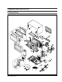
7. Exploded Views and Parts List
7-1 Exploded Views
D5
M1
M3
D1
M2
D7
M13
D4
M12
M6
M4
D6
M35
D2
M7
M9
M5
D3
M10
M8
M11
M36
M34
M14
M37
M16
M15
M33
M17
M20
M21
M32
M31
M22
M18
B2
M19
B1
M30
B3
M27
M38
M29
B5
B4
M24
C4
M23
M26
C3
C5
C6
M25
M43
M28
C1
M39
C2
M40
M42
M44
M41
Samsung Electronics
7-1
Exploded Views and Parts List
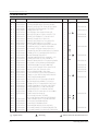
7-2 Main Parts List
Ref. No.
Parts No.
Description/Specification
M 1
M 2
M 3
M 4
M 5
M 6
M 7
M 8
M 9
M 10
M 11
M 12
M 13
M 14
M 15
M 16
M 17
M 18
M 19
M 20
M 21
M 22
M 23
M 24
M 25
M 26
M 27
M 28
M 29
M 30
M 31
M 32
M 33
M 34
M 35
M 36
M 37
M 38
M 39
M 40
M 41
M 42
M 43
M 44
DE70-30032X
DE63-90150A
DE61-50323A
DE61-30008A
DE61-70060A
DE47-70072A
DE60-40009B
DE63-20017A
DE61-50021A
DE61-50027A
DE61-50025A
DE39-20058C
DE71-60298A
DE91-40095A
DE31-30031A
DE47-20009A
DE03-30035A
4713-001004
DE71-60010A
DE61-50129A
DE93-20001A
DE66-90013A
DE91-70061B
DE61-50106A
DE91-70065A
2501-001014
DE26-10099A
DE61-40017A
DE80-10003A
DE31-10154A
DE47-20008A
DE71-60013A
DE61-80004A
DE61-80005A
DE47-20174A
DE65-20014A
PANEL-OUTER;T0.6 W351.2 L1010 WHT-COATIN
CUSHION-RUBBER;DFA20 T2 W100 L140 BLK
BRACKET-UPPER;ALSTAR T0.6 W385 L205 M624
SUPPORTER-HEATER;ALUMINA T12 CE745G
SPRING-PLATE;SK-5 T0.5
HEATER-GRILL;230V 1100W 47.OHM 6.25
WASHER-TEFLON;SLOT ID22.2 OD28 T1.2 TEFL
GASKET-HEATER;BRASS T1.5 OD30.5 ID22.5
BRACKET-FLANGE;SECC1 T0.8 32 32
BRACKET-HEATER;BSS2-A T(1.0) W(51) L(55)
BRACKET-EARTH;BSS2-A T1.0 CE745G
ASSY POWER CORD;KKP-4819D/B232 250V16A L
COVER-BACK;SECC T0.6 W273 L633 M6Q45
ASSY NOISE FILTER;SN-E10D(N) 250V 10A “2
FAN-MOTOR;SMF745EA 230V/50HZ ASSY-FAN-MO
THERMOSTAT;CS-7SA(160/60)187Y 250V7.5A 1
MAGNETRON;OM75PH((31)ESS
LAMP-INCANDESCENT;230V,-,40W,ORG,-,-,25x
COVER-AIR;PP(TB53) T1.7 WHT 64G M745
BRACKET-MOUNTING;SECC T0.8 W24 L316 M624
ASSY BODY LATCH;2ND-W1 M97G45/M9745
LEVER-DOOR;POM(F20-01) NTR MW5630T
ASSY-H.V.FUSE;THV060T-0750-H 5KV0.75A RE
BRACKET-HVC;SECC T0.8 W31 L125.8
ASSY-HVD;BMP28 SEMA 12KV SUMI
C-OIL;HCH212105C 1.05UF,2100V 35X54X85,2
TRANS-H.V;SHV-745EG1 230V 50HZ 2200V DPC
FOOT;PP(A353) BLK MW5630T
BASE-PLATE;SGCC1-Z T0.8 W340 L550 M745
MOTOR-DRIVE;M2HJ49ZR02,ST-16 21V 5/6
THERMOSTAT;CS-7S(100/60)187Y 250V7.5A 10
COVER-CEILING;MICA T0.5 W52 L118 CE745G
HINGE-LOWER;SCP1 T2.3 ZN-COATING BLK
HINGE-UPPER;SCP1 T2.3 BLK ZN-COATING
THERMOSTAT;NT-101NA 8XH 120 110 23.8MM
CABLE CLAMP;DA-6N NY-66
ASSY DOOR;PUSH WHT CE745GR
ASSY CONTROL-BOX;230V-50HZ CE745GR(CIS)
TRAY-COOKING;GLASS T5.0 PI288 780G M745
ASSY-GUIDE ROLLER;MW4370W
COUPLER;PPS 5GR BRN M97G45
RACK-WIRE;MSWR3 PI3 PI230 HI80 SNC2
ASSY WIRE HARNESS-E;230V50HZ M9G45 CTW
ASSY WIRE HARNESS-A;230V50HZ CE745G/CE94
DE74-20102B
DE92-90436A
DE67-60002A
DE74-70071A
DE39-40409A
DE39-40568A
: Option Parts
7-2
: Warning
Q'ty
1
1
1
1
1
1
1
1
1
1
1
1
1
1
1
1
1
1
1
1
1
1
1
1
1
1
1
2
1
1
1
1
1
1
1
1
1
1
1
1
1
1
1
1
Remarks
OLD PARTS NO.
73011-0243-00
76674-232-810
70534-0004-02
73404-0014-00
73312-0184-001
77059-0034-00
73013-0342-00
71533-0015-00
79163-0252-01
73013-0194-00
79169-0153-00
73004-0007-00
76449-0003-00
79204-0381-00
:Electrostatically Sensitive Devices
Samsung Electronics
Exploded Views and Parts List
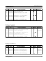
7-3 Door Parts List
Ref. No.
Parts No.
Description/Specification
Q'ty
D 1
DE64-40007A
DOOR-A;ABS(VH-080) T3.0 WHT
1
D 2
DE64-40006A
DOOR-KEY;POM(TC3005) T2.0 12GR BLK CE9
1
D 3
DE61-70033A
SPRING-KEY;ES HSWR10 PI0.6 D6.0 L22.3 BL
1
D 4
DE67-20004D
SCREEN-DOOR;PC T1.5 W173.6 L373.5 WHT CE
1
D 5
DE92-50126B
ASSY DOOR-E;COATING BLK CE745G
1
D 6
DE64-40008B
DOOR-C;PP T1.5 W L G BLK CE745G
1
D 7
DE01-00003B
FILM-DOOR;PC T0.2 W143 L265 TRP CE745G
1
Remarks
Old Parts No.
72724-0040-00
7-4 Control Parts List
Ref. No.
Parts No.
Description/Specification
Q'ty
C 1
DE66-20006A
BUTTON-PUSH;RESIN-ABS(HR-0370U) P/WHT M9
1
C 2
DE61-70076A
SPRING-BUTTON;HSWR PI0.6
1
C 3
DE34-10007C
SWITCH-MEMBRANE;PET 230V50HZ W89.7 L161.
1
C 4
DE72-70003A
CONTROL-PANEL;ABS(VH-080) WHT
1
C 5
DE67-40002A
WINDOW-DISPLAY;RESIN-ACRYLIC T2.3 M945(I
1
C 6
DE91-10377A
ASSY P.C.B-MAIN;230V50HZ NS V.F.D CE945G
1
Remarks
Old Parts No.
76674-239-310
7-5 Body Latch Parts List
Ref. No.
Parts No.
Description/Specification
Q'ty
B 1
DE66-40001A
LATCH-BODY;POM(F20-02) 40GR NTR
1
B 2
3405-000178
SWITCH-MICRO;VP-533A-OF-PS(T85) 250V,15A
1
73579-203-207
B 3
3405-000175
SWITCH-MICRO;VP-531A-OF(T85) 250V,15A,20
1
73579-203-278
B 4
3405-000178
SWITCH-MICRO;VP-533A-OF-PS(T85) 250V,15A
1
73579-203-207
B 5
DE66-90001A
LEVER-SWITCH;P.O.M(F20-02) 2 6 NTR 2ND-W
1
Samsung Electronics
Remarks
Old Parts No.
7-3
Exploded Views and Parts List
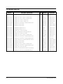
7-6 Standard Parts List
Parts No.
DE60-10012A
DE60-10012A
DE60-10012A
DE60-10122A
DE60-10122A
DE60-10098A
DE60-10082I
DE60-10082I
DE60-10080A
DE60-10080A
DE60-10069A
DE02-00029A
DE60-10069A
DE60-10012A
DE60-10098A
DE60-10098A
DE60-10082J
DE60-10082I
DE60-10082I
DE60-10012A
DE60-10098A
DE60-10052A
DE60-10018A
DE60-10013A
7-4
Description / Specification
SCREW-TAP TITE;TH + 3 M4 L10 SWR10 ZPC2
SCREW-TAP TITE;TH + 3 M4 L10 SWR10 ZPC2
SCREW-TAP TITE;TH + 3 M4 L10 SWR10 ZPC2
SCREW-TAP TH;TAP TH 2-4X8 FE FN
SCREW-TAP TH;TAP TH 2-4X8 FE FN
SCREW-ASSY TAPTITE;PH TC M4X8 SWRCH18A Z
SCREW-A;2S-4X12 FEFZY
SCREW-A;2S-4X12 FEFZY
SCREW-WASHER;M5 L12 2S
SCREW-WASHER;M5 L12 2S
SCREW-TAP TH;TH M4 L10 FRFZY
TAPE-SCOTCHPAR;POLYESTER 3M-893 W50
SCREW-TAP TH;TH M4 L10 FRFZY
SCREW-TAP TITE;TH + 3 M4 L10 SWR10 ZPC2
SCREW-ASSY TAPTITE;PH TC M4X8 SWRCH18A Z
SCREW-ASSY TAPTITE;PH TC M4X8 SWRCH18A Z
SCREW-TAPPING;TH 2S-4X8 MSWR3 ZPC YEL WS
SCREW-A;2S-4X12 FEFZY
SCREW-A;2S-4X12 FEFZY
SCREW-TAP TITE;TH + 3 M4 L10 SWR10 ZPC2
SCREW-ASSY TAPTITE;PH TC M4X8 SWRCH18A Z
SCREW-TAP PH;PH M4 L8 FEFZY
SCREW-ASSY MACHINE;PH M4X0.7P 8 MSWR10 S
SCREW-ASSY TAP;TH 2S 4 L12 MSWR3 ZPC3 FI
Q'ty
Remarks
Old Parts No.
1
1
2
2
2
2
4
4
4
4
1
1
3
2
1
1
1
2
2
1
2
2
2
2
NO-FIL
P-CO-E
HI-UPP
C-CEIL
B/HEAT
MO/DRI
OUT-PN
B-PLTE
MGT
HVT
CV/AIR
TR-CUS
B/UPP
HI-LOW
MEM-PN
CV-TCO
B/HVC
BD-LAT
CON-PA
C/GE-M
MGT-TC
GR-TCO
B/EATH
CV/BLW
70504-0002-00
70504-0002-00
70504-0002-00
77128-240-085
77128-240-085
A0103-0010
77154-203-8201
77154-203-8201
77154-202-910
77154-202-910
77128-540-101
70859-800-311
77128-540-101
70504-0002-00
A0103-0010
A0103-0010
77154-203-8401
77154-203-8201
77154-203-8201
70504-0002-00
A0103-0010
77108-540-081
70504-0019-00
70504-0004-00
Samsung Electronics
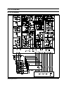
8. P.C.B Diagrams
8-1 P.C.B Diagrams
Samsung Electronics
8-1
P.C.B Diagrams
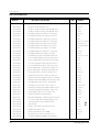
8-2 P.C.B Parts List
Parts No.
8-2
Description / Specification
Q'ty
Remarks
0401-001002
DIODE-SWITCHING;1N4148M,100V,200mA,500mW
16
D5~20
0402-000559
DIODE-RECTIFIER;D4G,400V,1A,T-1
3
D01,2,4
0501-000283
TR-SMALL SIGNAL;KSA539-Y,PNP,400mW,TO-92
1
TR01
0501-000388
TR-SMALL SIGNAL;KSC815-Y,NPN,400mW,TO-92
1
TR03
2001-000003
R-CARBON;330ohm,5%,1/8W,AA,TP,1.8x3.2mm
2
R03,04
2001-000037
R-CARBON(S);330ohm,5%,1/2W,AA,TP,2.4x6.4
1
R02
2001-000273
R-CARBON;100Kohm,5%,1/8W,AA,TP,1.8x3.2m
1
R12
2001-000290
R-CARBON;10Kohm,5%,1/8W,AA,TP,1.8x3.2mm
6
R9,10,14,15,16,43
2001-000429
R-CARBON;1Kohm,5%,1/8W,AA,TP,1.8x3.2mm
7
R05~08,17~19
2001-000613
R-CARBON;3.9Kohm,5%,1/8W,AA,TP,1.8x3.2m
1
R11,13,20,21,22,23,42
2001-000776
R-CARBON;470ohm,5%,1/2W,AA,TP,3.3x9mm
1
R01
2001-000786
R-CARBON;47Kohm,5%,1/8W,AA,TP,1.8x3.2mm
12
R30~41
2011-001043
R-NETWORK;47Kohm,5%,1/8W,A,SIP,8P,BK
1
AR01
2202-000780
C-CERAMIC,MLC-AXIAL;UP050F104Z 100NF,+80
6
C6,9,10,11,12,15
2401-000247
C-AL;1SA1ANB107MAN 100UF,20%,10V,GP 6.3X
1
C04
2401-000353
C-AL;1SA1HWB101M 100UF,20%,50V,GP 10X16X
1
C02
2401-000914
C-AL;CESSL1C220M0511AA 22UF,20%,16V,GP 5
1
C05
2401-001412
C-AL;1SG1VFB477MAN 470UF,20%,35V,GP 10X1
1
C01
3501-001014
RELAY-POWER;OM1F-S-124LM 24V,21.8MA,17A
1
RY01
3501-001015
RELAY-POWER;OZF-S-124LM1P 24V,21.8MA,16A
1
RY04
3501-001016
RELAY-MINIATURE;JV24-KT 24V,12.5MA,5A 1F
2
RY02,03
3708-000528
CONNECTOR-FPC/FC/PIC;FCZ254-13SL,BLK 13P
1
CN02
3711-000203
CONNECTOR-HEADER;YW396-03AV WHT STRAIGHT
1
CN01
3711-000881
CONNECTOR-HEADER;SMW250-03,WHT BOX,3P,1R
1
CN03
A1018-0067
R-NETWORK;RN 1/8 X 6P 473-J T MHR5A473J
1
AR02
A1100-1049
C-CERAMIC;CC OA CH 50V T 220-J 3.5X1.9 U
6
C7,8,16~19
A4060-0008
TR-W/RESISTOR;KSR1005 300MW 100MA 50V EB
5
TR2,4~8
A4060-0009
TR-W/RESISTOR;KSR2005 300MW -100MA -50V
1
TR09
A4106-0154
DIODE-ZENER;TZP5.1B 5.1/5.7V 40MA T 1W
3
ZD1,2,3
A6010-0461
CONNECTOR-WAFER;YW396-04V WHT
1
CN04
B1283-0030
RESONATOR-CERAMIC;4.19MHZ 4.19MSTAR 2/CN
1
X-TAL
DE07-10081A
V.F.DISPLAY;SVM-4SM03 GRN/RSHORG 4 51 81
1
VFD
DE09-30479A
IC-MCU;KS56C671-43 DIP CE945G/CE745G
1
IC01
DE13-20009A
IC;KA7533 DIP
1
IC02
DE26-20141A
TRANS-L.V;SLV-945E 230V 50HZ AC17/2.9V
1
LVT1
DE30-20016A
BUZZER;CBE2220BA STICK
1
BUZ1
DE39-60001A
WIRE-SO COPPER;PI0.6 SN T 52MM
26
J01~26
DE60-60012A
PIN-EYELET;ID2.1 OD2.5 L3.0 SN BSP T0.25
8
E1~8
DE61-90004A
HOLDER-DIGITRON;NYLON#66 1.5 85 36 8GR B
1
Samsung Electronics
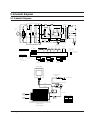
9. Schematic Diagrams
9-1 Schematic Diagrams
MGT
TCO
ASSY CHOKE P.C.B
H.V.TRANS
PRIMARYS/W
BLK
BLK
BLK
BLK
COM
C3
FUSE
BLU
BLK
230V40W
L
LAMP
WHT
1ND
GRILL
RELAY
F-MOTOR
L.V.TRANS
YEL
MAIN RELAY
WHT
RESISTOR
C1
HEATER
YEL
21V
DM
FM
H.V.FUSE
(0.75A-CE745G/
0.8A-CE945G)
COM
NC
0V
NO
H.V.CAPACITOR
ORG
WHT
BLK
INRUSH RELAY
BLK
MONITOR FUSE
(250V1.6A)
C2
CAVITY
TCO
BLU
H.V.DIODE
ORG
230V
BLU
D-MOTOR
POWER
CORD
230V/50HZ
230V
BLK
250V10A
BRN
CAVITY
TCO
BRN
RESISTOR
BLU
0V
F
BLU
YEL
FA
MAGNETRON
WHT
WHT
POWER RELAY
(SECONDARY INTERLOCK)
MAIN
RELAY
L.V.T
CONDITION OF OVEN
POWER
RELAY
INRUSH
RELAY
DOOR SENSING
S/W
GRILL
RELAY
KEY BOARD
1.INPUT : 230V
2.DOOR : OPEN
3.LAMP : ON
4.
: P.C.B PATTERN
5.
: P.C.B IN/OUT POINT
DOOR IS OPENED
COOK OFF
A S S Y M A I N P.C.B
WIRING COLOR
BRN : BROWN BLU : BLUE
WHT : WHITE ORG : ORANGE
RED : RED
YEL : YELLOW
BLK : BLACK
Y/G : YELLOW GREEN
COM NO
BLK
COM NO
BLK BLK
NC
COM NO
ORG
ORG
PRIMARY LATCH
SWITCH
WHT BLK
BLK BLU
BLK
DOOR SENSING
SWITCH
MONITOR
SWITCH
MAGNETRON
HIGH VOLTAGE
DIODE
FA
TO CHASSIS
F
HIGH VOLTAGE CAPACITOR
RED
RED
RED
H.V.FUSE
BLK
WHT
RED
SYMBOL COLOR
BRN BROWN
BLK
BLACK
RED
RED
BLU
BLUE
HIGH VOLTAGE
TRANSFORMER
Samsung Electronics
9-1


![[SPT-3000] e](http://vs1.manualzilla.com/store/data/005667089_1-a5f3766b3193f6552f250995926a69c5-150x150.png)