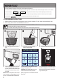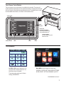
1
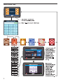
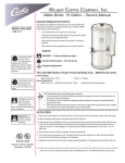
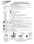
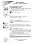
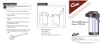
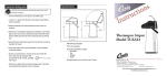
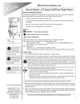
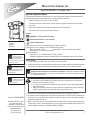
Wilbur Curtis Company, Inc.
Service Manual – Omega Twin
Important Safeguards/Symbols
This equipment is designed for commercial use. Any servicing other than cleaning and routine maintenance
should be performed by an authorized Wilbur Curtis Company Service Technician.
• DO NOT immerse the unit in water or any other liquid
• To reduce the risk of fire or electric shock, DO NOT open service panels. There are no user serviceable parts inside.
• Keep hands and other items away from hot areas of the unit during operation.
• Never clean with scouring powders or harsh chemicals.
Symbols:
WARNINGS – To help avoid personal injury
Important Notes/Cautions – from the factory
Model
OMGT
OMGT10
OMGT16
CAUTION: Please use
this setup procedure
before attempting to use
this brewer. Failure to follow the
instructions can result in injury or the
voiding of the warranty.
IMPORTANT: Equipment
to be installed to comply
with applicable governmental plumbing/electrical codes
having jurisdiction.
CAUTION: DO NOT
connect this brewer to hot
water. The inlet valve is
not rated for hot water.
Sanitation Requirements
This Curtis G4 Unit is Factory Pre-Set and Ready to Go Right from the Box.
Following are the Factory Settings for your G4 Coffee Brewing System:
• Brew Temperature = 200°F
• Water Bypass = 20% Lrg, 20% Med, 10% Sml Brew
• Brew Volume = Set to Vessel Requirement.
System Requirements:
• Water Source 20 – 90 PSI (Minimum Flow Rate of 4 GPM)
• Electrical: See attached schematic for standard model or visit www.wilburcurtis.com for your model.
SETUP STEPS
1. The unit should be level (left to right - front to back), on a secure surface.
2. Connect the water line to the water inlet fitting at the rear of the unit. Water volume flow to the machine should
be consistent. Use tubing sized sufficiently to provide a minimum flow rate of four gallons per minute.
NOTE: A water filtration system must be used to help maintain trouble-free operation. Air must be
purged from the cartridge prior to connection to equipment. In areas with extremely hard water,
we highly recommend the use of a Curtis approved water filter. For our full line of filters, please log
on to www.wilburcurtis.com.
NSF International requires the following water connection:
1. A quick disconnect or additional coiled tubing (at least 2x the depth of the unit) is required so
that the unit can be moved for cleaning.
2. This unit must be installed with adequate back-flow protection to comply with applicable federal,
state and local codes.
3. Water pipe connections and fixtures directly connected to a potable water supply shall be sized,
installed and maintained in accordance with federal, state, and local codes.
3. Connect the unit to electrical outlet with appropriate amperage rating (see serial tag on machine).
ISO 9001:2008 REGISTERED
WILBUR CURTIS CO., INC.
6913 West Acco Street
Montebello, CA 90640-5403
For the latest information go to
www.wilburcurtis.com
Tel: 800-421-6150
Fax: 323-837-2410
4. Once power has been supplied to the unit, flip the main power switch to the ‘ON’ position (located on the
right side of the unit), the water tank will begin to fill. When the water level in the tank reaches the probe,
the heating element(s) will turn on.
5. Water in the heating tank will require approximately 45 minutes before reaching operating temperature
(factory setting of 200°F). Where applicable, turn on the Universal Control Module (UCM). When the unit
reaches operating temperature, it will display “READY TO BREW”.
Technical Support: 1-800-995-0417 M-F 5:30am-4:00pm PT
Email: [email protected]
1
Your Curtis G4/Gold Cup Series is Factory Pre‑Set for Optimum Performance.
After connection to water and power; turn on the brewer at the rear toggle switch. You will hear a beep and the status lights will come on for a moment.
The screen will display
MODEL NUMBER
CONTROL BD NUMBER
. Next
When the proper level is reached
FILLING
HEATING will
is displayed. Water will fill the tank (3-5 minutes depending on water flow rate).
appear on the screen. It takes approximately 45 minutes to reach the set point temperature.
Control will display READY
TO BREW when temperature reaches the set point. The unit is now ready to brew.
COFFEE BREWING INSTRUCTIONS
1. Brewer should be ON. Confirm this at the toggle switch on the right side of the brewer. The touch screen should read Ready to Brew.
2. Place an empty coffee container centered beneath the brew cone.
WARNING – AVOID SCALDING: USE BOTH HANDLES FOR BETTER CONTROL. The brew cone may be filled with hot coffee
grounds and is difficult to manage with one hand.
The coffee vessel is heavy when full. Take precautions to avoid dropping while moving.
3. Place a new paper filter into the brew
cone.
6. Start the brew cycle by hold your finger
on the desired brew icon. As soon as
you hear the click of the brew valve, the
brew cycle has started and you can lift
your finger.
Brew Code: You may find that when a brew
button is pressed, a key pad appears on the
screen. This is a brew lock-out feature that
2
4. Fill the brew cone with the proper
amount of ground coffee.
requires a code to be entered before a brew
will start. The default is OFF.
CAUTION: When enabled, as soon as you
enter the brew code a brew cycle starts.
Refer to page 8 for more information about the
Brew Code.
5. Transfer the filled brew cone to the
brewer.
During the brew cycle, an animated 3 gallon
server icon will appear on the screen and a
brew timer will count down the time remaining on the brew cycle.
Touch Screen Control Module
The touch screen turns on when power is available to the controller. The screen will
contain standard control feature such as symbols and buttons. Pressing these elements
with your finger tip will activate the programming functions. The default screen, as well
as some added control buttons, are shown in the illustration below.
STATUS LIGHTS
BREW
BUTTONS
CURTIS LOGO
TO ENTER PROGRAMMING
Tap Curtis logo 5 times to bring
up the ACCESS CODE screen.
CONTROL SYMBOLS
All of these symbols may not be
visible at one time.
RETURN TO HOME
UNDO
SCROLL
ENTER
PROGRAMMING
ACCESS CODE screen. Default is 1 2 3 4.
Once the code is entered, press OK. The
Main Menu screen will appear.
The access code can be reset in Control
Settings, PASSWORDS.
MAIN MENU screen contains six control icons:
RECIPES, CONTROL SETTINGS, BREW SETTINGS,
MODEL SELECT, SETTINGS SUMMARY and EXIT.
PROGRAMMING Continued . . .
3
Menu Tree
This chart explains how to enter the program mode and menu selections available from the MAIN MENU.
4
Menu Features
5
Menu Features
6
System Fault Messages
7
Brew Access Code
8
Illustrated Parts
Main View
3
4
55
5
6
7
8
10
11
1
2
12
9
Item №
Part №
Description
1
WC-3705HW*
KIT, FAUCET S SERIES HOT WATER
2
WC-1825*
FAUCET, ASSY HOT WATER TP2S
3
WC-61912
LID, ASSY OMGT
4
WC-53115
TRIM, EDGE VINYL METAL CORE (4 FT)
5
WC-13464
HARNESS ASSY, OMGT
5A
WC-13464-101 HARNESS, ASSY OMGT10 & OMGT16
6
WC-172 *
SWITCH, ROCKER STYLE “SWITCH ONLY” 50 AMP
7
WC-10008
UNIVERSAL HOST ADAPTER (USB - G4)
8
WC-14017
PLUG, DOME 0.75”DIA HOLE BLACK NYLON 6/6,OMGT/S
9
WC-3528
LEG, 4” ADJUSTABLE 3/8-16 THREAD
10
WC-594-101
TRANSFORMER, 250VA, 208/230/400/460/575VAC TO
24/115/230VAC OMGT16
11
WC-61818-103 FRONT COVER ASSY, NON-METAL BREW CONE OMGT
12
WC-61819
BRACKET, SERVER STOP
* Suggested Parts to Stock
9
Illustrated Parts
Heating Tank
22
23
14
24
25
15
18
26
19
27
16
19
17
18
13
20
21
20
Item №
10
Part №
Description
13
WC-37317*
KIT, STRAIGHT FITTING & BUSHING GEN USE
14
WC-61832
LID ASSY, HEATING TANK
15
WC-43142*
GASKET, TANK LID
16
WC-37357*
KIT, STRAIGHT PLASTIC FITTING AND BUSHING 12MM
17
WC-5527K*
KIT, PROBE WATER LEVEL FITTING, O’RING, NUT
18
WC-2630
BUSHING, CONICAL BLIND
19
WC-37266
KIT, FITTING TANK OVERFLOW
20
WC-37780-101 TUBE, INLET MANIFOLD ASSY
21
WC-1438-101* SENSOR, TANK TEMPERATURE
22
WC-2977-101K KIT,SPRAYHEAD FITTING PLASTIC
23
WC-43055
GUARD, SHOCK RESET THERMOSTAT
24
WC-43149
GUARD, HEATING ELEMENT
25
WC-522 *
THERMOSTAT, HI LIMIT HEATER DPST 277V-40A
26
WC-979-101*
ELEMENT, HEATING 4000W 208V VERTICAL OMGT
26A
WC-979*
ELEMENT, HEATING 4000W 240V OMGT10
27
WC-54328
TANK, COMPLETE 208V 12KW OMGT
27A
WC-54328-102 TANK, COMPLETE 240V 12KW OMGT10
* Suggested Parts to Stock
Illustrated Parts
Top Wrap
28
37
44
45
31
32
39
40
33
34
38
30
29
35
36
46
47
41
42
43
Item №
Part №
Description
28
WC-8559*
RELAY, SOLID STATE 40A W/INTEGRATED HEATSINK
29
WC-1516
30
WC-588*
BREAKER, CIRCUIT 2-POLE 20A/250VAC
NOISE, EMI FILTER 250VAC 20A
31
WC-442
SOLENOID, LOCK BREW CONE RIGHT 120VAC
32
WC-12012*
VALVE, DUMP .50 INCH 120VAC 50-60HZ
33
WC-10001*
UNIVERSAL POWER MODULE G4
34
WC-589-101*
TRANSFORMER, 120/230VAC-24VAC 4.8VA W/LEADS
35
WC-10000*
CONTROL MODULE (UCM), TOUCH SCREEN G4
36
WC-4212-02
NUT, 5/8-18 JAM PLASTIC ULTEM
37
WC-890-102*
VALVE, INLET 120V-10W 4GPM
38
WC-2471
ELBOW, SILICONE
39
WC-2977-02
FITTING, SPRAYHEAD ULTEM (NO INSERT)
40
WC-43089
GASKET, 1.00”OD x .625” I.D. x .030” THK SILICONE
41
WC-43141*
O-RING, 7.484 I.D. X .139 THICK BUNA-N
42
WC-43140*
O-RING, .984 I.D. X .130 THICK BUNA-N
43
WC-29086
SPRAYHEAD, PLASTIC 8 INCH DIAMETER
44
WC-2402P
ELBOW, 3/8 NPT x 3/8 FLARE PLATED
45
WC-29089-101 FITTING, 3/8” MNPT x 3/8” HOSE BARB SS
46
WC-39982
LABEL, FRONT WRAP OMEGA
47
WC-39805
LABEL, GOLD CUP NAMEPLATE
* Suggested Parts to Stock
11
Illustrated Parts List
48
50
54
49
52
53
51
Item №
Part №
Description
48
WC-5231*
COMPOUND, SILICONE 5 OZ TUBE
49
GEM-6-103*
FILTER, PAPER 20 X 8 OMEGA
50
WC-5350 *
TUBE, SILICONE .50 ID x .75 OD (3 FT)
51
WC-33004
BREW CONE ASSY, NON-METAL OMEGA
52
WC-43059*
CLAMP, HOSE SNAP NYLON .616/.707
53
WC-43058
PLUG, TANK DRAIN
54
WC-5310 *
TUBE, 5/16 ID X 1/8 W SILICONE (10 FT)
55
WC-390092
LABEL, FRONT OMEGA CURTIS LOGO
* Suggested Parts to Stock
12
Electrical Schematic OMGT
13
Electrical Schematic OMGT10
14
Electrical Schematic OMGT16
15
Cleaning the Coffee Brewer
Regular cleaning and preventive maintenance is essential in keeping your coffee brewer looking and working like new.
CAUTION – Do not use cleansers, bleach liquids, powders or any other substance containing chlorine. These products
promote corrosion and will pit the stainless steel. USE OF THESE PRODUCTS WILL VOID THE WARRANTY.
1. Wipe exterior surfaces with a clean cloth. Scrub off coffee spots, spills, or coffee grounds.
2. Remove the brew cone to clean. Rinse and dry the brew cone.
3. With the brew cone removed, wipe the spray head and the area surrounding the spray head with a clean moistened cloth. Dry
the area.
4. Rub a stainless-steel polish on the outside surfaces of the brewer cabinet as a protection for the metal.
Cleaning the Non-Metal Brew Cone
Once a week clean the brew cone and handle. Prepare a mild solution of dish washing detergent and warm water.
1. Use a nylon brush soaked in cleaning solution to remove coffee oils and coffee grounds within the brew cone. Brush between
the filter suspending ribs.
2. Disassemble the two handles from the brew cone for cleaning.
a. Use a slotted screwdriver to remove the four slotted screws.
b. Take a nylon brush soaked in cleaning solution to brush out the hard
to reach recessed, inside part of the handle. Pay special attention to
the attachment channels of the handle.
c. Rinse the handles and the brew cone
to remove all detergent residue.
3. Dry the brew cone and handle.
4. Assemble handles onto the brew cone.
16
USE A NYLON SPIRAL BRUSH,
SOAKED IN A DETERGENT
SOLUTION, TO CLEAN INSIDE
THE HANDLE.
Rough-In Drawing
17
Product Warranty Information
The Wilbur Curtis Company certifies that its products are free from defects in material and workmanship under normal use. The following limited
warranties and conditions apply:
3 Years, Parts and Labor, from Original Date of Purchase on digital control boards.
2 Years, Parts, from Original Date of Purchase on all other electrical components, fittings and tubing.
1 Year, Labor, from Original Date of Purchase on all electrical components, fittings and tubing.
Additionally, the Wilbur Curtis Company warrants its Grinding Burrs for Forty (40) months from date of purchase or 40,000 pounds of coffee,
whichever comes first. Stainless Steel components are warranted for two (2) years from date of purchase against leaking or pitting and replacement parts are warranted for ninety (90) days from date of purchase or for the remainder of the limited warranty period of the equipment in which
the component is installed.
All in-warranty service calls must have prior authorization. For Authorization, call the Technical Support Department at 1-800-995-0417. Effective
date of this policy is April 1, 2003.
Additional conditions may apply. Go to www.wilburcurtis.com to view the full product warranty information.
CONDITIONS & EXCEPTIONS
The warranty covers original equipment at time of purchase only. The Wilbur Curtis Company, Inc., assumes no responsibility for substitute replacement parts installed on Curtis equipment that have not been purchased from the
Wilbur Curtis Company, Inc. The Wilbur Curtis Company will not accept any responsibility if the following conditions are not met. The warranty
does not cover and is void under the following circumstances:
1) Improper operation of equipment: The equipment must be used for its designed and intended purpose and function.
2) Improper installation of equipment: This equipment must be installed by a professional technician and must comply with all local electrical,
mechanical and plumbing codes.
3) Improper voltage: Equipment must be installed at the voltage stated on the serial plate supplied with this equipment.
4) Improper water supply: This includes, but is not limited to, excessive or low water pressure, and inadequate or fluctuating water flow
rate.
5) Adjustments and cleaning: The resetting of safety thermostats and circuit breakers, programming and temperature adjustments are the
responsibility of the equipment owner. The owner is responsible for proper cleaning and regular maintenance of this equipment.
6) Damaged in transit: Equipment damaged in transit is the responsibility of the freight company and a claim should be made with the carrier.
7) Abuse or neglect (including failure to periodically clean or remove lime accumulations): Manufacturer is not responsible for variation
in equipment operation due to excessive lime or local water conditions. The equipment must be maintained according to the manufacturer’s
recommendations.
8) Replacement of items subject to normal use and wear: This shall include, but is not limited to, light bulbs, shear disks, “0” rings, gaskets,
silicone tube, canister assemblies, whipper chambers and plates, mixing bowls, agitation assemblies and whipper propellers.
9) Repairs and/or Replacements are subject to our decision that the workmanship or parts were faulty and the defects showed up under normal
use. All labor shall be performed during regular working hours. Overtime charges are the responsibility of the owner. Charges incurred by
delays, waiting time, or operating restrictions that hinder the service technician’s ability to perform service is the responsibility of the owner
of the equipment. This includes institutional and correctional facilities. The Wilbur Curtis Company will allow up to 100 miles, round trip, per
in-warranty service call.
RETURN MERCHANDISE AUTHORIZATION: All claims under this warranty must be submitted to the Wilbur Curtis Company Technical
Support Department prior to performing any repair work or return of this equipment to the factory. All returned equipment must be repackaged
properly in the original carton. No units will be accepted if they are damaged in transit due to improper packaging. NO UNITS OR PARTS WILL
BE ACCEPTED WITHOUT A RETURN MERCHANDISE AUTHORIZATION (RMA). RMA NUMBER MUST BE MARKED ON THE CARTON
OR SHIPPING LABEL. All in-warranty service calls must be performed by an authorized service agent. Call the Wilbur Curtis Technical Support Department to find an agent near you.
ECN 16016 . 7/16/[email protected] . rev E
ECN 15667 . 2/19/[email protected] . revD
ECN 15539 . 12/19/[email protected] . revWILBUR
C
CURTIS CO., INC.
9/6/[email protected] . ECN 15315 . rev B
12/20/[email protected] . ECN 14647 . revA6913
.
Acco St., Montebello, CA 90640-5403 USA
2/17/[email protected] . EDR 8139 . EAR 10220
Phone: 800/421-6150
Fax: 323-837-2410
9/28/[email protected] . ECN 14451 . Rev ATechnical Support Phone: 800/995-0417 (M-F 5:30A - 4:00P PST)
2/17/[email protected] . EDR 8139 . On 9/13/12,
Web Site: www.wilburcurtis.com
fixed LD (p11).
18
E-Mail: [email protected]
7/2014 . F-3835 rev E