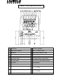
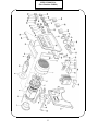
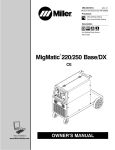
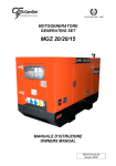
1
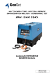
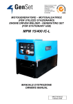
ENGINE DRIVEN WELDER
GENERATING SET
MPM 12/400 I-KA
(Part Number 636804)
DOC No: EDW0005
Issue No: 2
Date: 16-July-97
GENERAL USE INSTRUCTIONS
Read the instructions carefully; proceed according to the regulations in use in the
country where the machine will operate.
TRANSPORTATION
Y The machine must be fixed securely to the motor vehicle if it has to be moved to the
place of use. Raise the machine using the lifting eye if the model provides it;
otherwise, lift it using a forklift, taking care that the weight is well balanced on the
two forks. Keep well clear during these operations; furthermore, we suggest not to
keep the machine suspended for long.
Y If the machine is mounted on a wheels trolley or trailer, be sure the machine is stable
and secure before use.
CAUTION
Y Note: The generating set or the welder is furnished WITHOUT lubricating oil.
Provide the machine with "10 W 40" multi-grade oil indicated for temperatures
from - 20°C to 40° C in the quantity indicated in the engine SPECIFICATION
section.
Y Note: If the machine is fitted with a water cooled engine fill the radiator circuit with a
solution made up by 50% water and 50% antifreeze liquid in the quantity indicated in
the engine SPECIFICATION section.
Y Note: The generating set is furnished with a flat battery and without acid. Fill it using
sulphuric acid in a 30% - 40% concentrated solution to cover the elements. During
this operation, we suggest the operator use protective gloves and goggles; accidental
skin contact with the sulphuric acid solution must be washed up immediately with
cold water and, if necessary, a doctor must be consulted.
Y Note: Do not disconnect battery cables when the engine runs. This could result in
serious damage to the machine.
Y Note: BEFORE OPERATING THE MACHINE the neutral, or the equivalent
winding point, MUST be connected effectively to earth using an earth stake (without
any switch or other device that may interrupt the electrical connection) from the earth
stud available on the machine, and identified by the symbol:
Y
Y Note: for normal transportation, follow the instructions as specified in the
TRANSPORTATION section.
1
RUNNING IN
For the first 50 hours of operation of the machine do not employ more than 70% of the
maximum power indicated in the technical specifications.
STARTING AND WORKING
1- Make the earth connection (see the USE INSTRUCTIONS).
2- If the machine model IS NOT equipped with a earth leakage circuit breaker the
available socket is intended ONLY for connecting the machine to a switchboard
equipped with all protection devices imposed by current law regulations.
3- Check the state and efficiency of the cables.
4- Make sure that all the switches and electric connections are in the right position for
starting (see USE INSTRUCTIONS and CONTROL PANEL DESCRIPTIONS).
5- Use the machine in well ventilated places, taking care that the exhaust gas and the
welding fumes produced (where welders are used) do not stagnate. Keep the machine
away from walls or other obstacles in order to avoid air or gas recycling. If the
machine is employed in closed places, use forced ventilation in order to ensure proper
air recycling.
6- While welding, eyes and body must be protected by gloves, mask and appropriate
clothes.
7- Fuel refill must not be made while smoking or close to flames. This operation must
be done when the engine is switched off.
8- Do not over fill the tank and clean up any spillage.
9- Check daily for loss of fuel or lubricating oil.
10-For machines provided with a liftable canopy engage the canopy securing brackets
where fitted.
WARNING
Y Do not connect the machine to the commercial electric network.
Y Do not work close to flammable materials or where there is explosive gas or vapours.
Y Do not work in confined or poorly ventilated places.
Y Do not touch the exhaust muffler or adjacent components.
Y Do not carry out service operations while the engine is running.
Y Any service on the electrical circuit must be done when the engine is stopped and only
by qualified technicians.
Y Keep clear of moving parts of the engine while it is operating and do not approach the
machine with loose fitting clothing.
SERVICE AND CLEANING
We suggest frequent cleaning of the machine since the presence of dirt can compromise
efficiency.
The frequency of this operation depends on the environment in which the machine is
used. We advise to pay special care to the service of::
OIL LEVEL, OIL FILTER, AIR FILTER, FUEL FILTER, COOLING LIQUID
LEVEL, RADIATOR, VENTILATION DUCTS AND INTAKES, BATTERY
ENGINE USE AND SERVICE manual and the SPECIFICATION section to know
how and when it is useful to do it. The extraordinary service operations not mentioned
herein require the aid of specialised technicians (see the Engine Dealers list).
2
For service intervals consult the ENGINE USE AND SERVICE manual and the
SPECIFICATION.
ADJUSTMENTS AND REGULATIONS
All necessary controls are located on the main control panel and are properly explained
in the section FRONT PANEL DESCRIPTION.
We advise the operator against tampering with the engine or the internal electrical
components.
Note: Modification of the normal parameters can compromise the reliability of the
machine.
PROLONGED STANDING PERIODS
If the machine has to be stopped for a long period (more than one year), we suggest to
leave the motor oil and the fuel in and the water in the radiator in order to avoid
oxidising effects.
When the machine is to be used, the liquids must be replaced, the battery must be
charged; the belts, pipes and rubber hoses must be checked and a visual inspection of the
electrical connections must be done.
SCRAPPING
In order to preserve the environment, it is advised to dispose of the oil, fuel and battery
in an approved manner. For the complete range of materials, see the list below:
FERROUS and NON-FERROUS MATERIALS:
steel, cast iron, aluminium, copper, brass are used in the structure of engine,
alternator, transformers, etc.
PLASTIC MATERIALS:
rubber, bakalite, epovit, lexan are used for the instruments, engine pipes,
junction boxes and connectors, fuel tank, fuel cap, wheels, anti-vibration
dampers, condenser housings, fans, belts, filters and hoses.
ELECTRONIC MATERIALS:
various components, diodes, resistors, electronic panels.
VARIOUS MATERIALS:
rock wool, sound proofing materials.
LIQUIDS:
fuel, gasoline, cooling liquids, battery acid.
3
TECHNICAL SPECIFICATION
POWER PLANT INFORMATION
Part number
636804
Description
MPM 12/400 I-KA
WELDING GENERATOR D.C.
Maximum power
400A @ 36V
Rated output at 60% duty cycle
350A @ 34V
Range of continuous control
30A to 400A
Duty cycle period
5 minutes
DC open circuit voltage
70V
Insulation class
F
Mechanical protection
IP 23
CC mode
30A to 400A
CV mode
18V to 40V
AUXILIARY GENERATOR
Generator type
Asynchronous
Three phase power
12kVA @ 400V
Single phase power
10kVA @ 230V
Frequency
50 Hz
RECOMMENDED MANUAL METAL ARC WELDING ELECTRODE
Electrode Description
Maximum Electrode Diameter
General purpose & low hydrogen
6.0mm
Cellulose
6.0mm
Iron powder
6.0mm
4
ENGINE
Make/Type
Kubota D 1105-E
Number of cylinders
3
Displacement
1124 cc.
Diesel engine output
25 HP
Engine speed
3000 rpm
Cooling
Water
Fuel tank capacity
36.5 Litres
Oil capacity
5.1 Litres
Starter
Electric
Battery
12V - 43 Ah
Acoustic energy emission
97 dB(A)
Acoustic pressure @ 1 metre
89 dB
Acoustic pressure @ 4 metre
77 dB
Average fuel consumption
275 gram/kW/hour
Average operating hours
15 hours
DIMENSIONS AND WEIGHT
Dimensions (Length x Width x Height)
1590mm x 730mm x 920 mm
Weight
460 Kg
5
ENGINE WARRANTY
AND SPARE PARTS
1.1 INTRODUCTION
Carefully follow the KUBOTA engine operation manual for safe operation and long service life of
this product.
1.2 ENGINE WARRANTY
To secure warranty for the engine ensure that the warranty certificate is fill in and mailed to the Tutts
state branch office (KUBOTAs Australian engine distributor).
The engine is warranted for twelve (12) months from date of purchase or one thousand (1000) hours
which ever is sooner. This warranty is limited to the replacement or repair, at Tutts workshop of any
parts proven defective, under normal use and service within the warranty period. For warranty
service outside a Tutts workshop, all travelling time and mileage incurred, will of necessity, be
charged to the owner of the equipment who ordered the off site warranty repair(s).
New engine warranty does not apply to maintenance items such as filters, hoses, belts, preheaters,
injection nozzles, packing and seals, etc.
Tutts Branch Network Tutts (Sydney):
Tutts (Perth):
Tutts (Brisbane):
Tutts (Melbourne):
2 South St. Rydalmere NSW 2116
50 Great Eastern Hwy South Guildford WA 6055
39 Suscatand St Rocklea QLD 4106
Gwelo St Tottenham VIC 3012
Tutts Dealer Network
Queensland:
Andrew's Agricultural Centre Pty Ltd Fishabout Pty Ltd
Dore Power Equipment Pty Ltd
New South Wales: SJ & ML Foster
Clares Diesel Service Pty Ltd
Kentan Pty Ltd
Tasmania:
Diesel & Marine Pty Ltd
South Australia:
Mac Pac Sales & Service Pty Ltd
-
Goranvale, Cairns Ph: (070) 565222
Innisfail Ph: (070 616466
Tully Ph: (070) 681311
Mackay Ph: (079) 534752
Roma Ph: (076) 221883
Moree Ph: (067) 525 488
Coffs Harbour Ph: (066) 525121
Hexham, Newcastle Ph: (049) 648275
Newtown, Hobart Ph: (03) 62281755
Wingfield, Adelaide Ph: (08) 82431422
1.3 SPARE PARTS
KUBOTA engine: Contact Tutts (in Australia) for spare parts and service assistance. Specify the
engine model number, serial number, name of part (with code number), Engine
Driven Welder model name (with code number) and manufacturers name when you
contact your KUBOTA Dealer. KUBOTA guarantees an efficient technical support
throughout Australia and New Zealand.
Generator and equipment: Contact your local CIGWELD Distributor for spare parts. Specify the
Engine Driven Welders model number, serial number and name of part
(with code number) when ordering spare parts. Refer to the Spare Parts
List from page 13.
6
FRONT PANEL DESCRIPTIONS
A Ignition key
O Arc force regulator
B Single phase voltmeter
P Basic / Cellulose switch
C Hourmeter
Q Wire feeder connector 14 pin
D Water temperature lamp
R 230V single phase outlet
E Battery charge lamp
S 400V three phase outlet
F Oil pressure lamp
T 16A single phase circuit breaker
G Glow plug lamp
U ELCB (25A earth fault protection)
H Fuel meter
V Serial number
I Throttle switch
Z Earth connection
L CC/CV mode select
X Welding socket : negative connection
for CV-WORK
M Welding current control
Y Welding socket : negative connection
for CC-WORK
N Remote control switch
W Welding socket : positive connection
7
OPERATING INSTRUCTIONS
1.1 EQUIPMENT
GROUNDING CONNECTION
^ This machine has auxiliary power capability and grounding of the frame and case is
recommended. Refer to your local Supply Authority or Australian Standard AS3000 for
detailed earthing instructions. Connect the earth wire to the Earth connection located
on the front of the machine.
2.1 EARTH FAULT PROTECTION
^ Supply Authorities recommend that protection devices immediately disconnect all power
in the event of an earthing fault. This equipment is fitted with a Earth Leakage Circuit
Breaker (ELCB) that interrupts the auxiliary power circuit within 0.2 seconds when the
earth leakage is greater than 30 mA.
^ If a fault occurs in equipment connected to the auxiliary power supply, the outer casing
may become live and result in serious injury. The Engine Driven Welder must be
properly earthed. Refer to your local Supply Authority or Australian Standard AS3000
for detailed earthing instructions. The user is responsible for connecting this Engine
Driven Welder to earth.
3.1 USE AND TESTING OF EARTH FAULT PROTECTION
^ Switch the ELCB lever up to setting I (ON). Test by pressing the test button while the
engine is running. This will result in the ELCB tripping resulting the lever returning to
setting 0 (OFF). Reset to setting I (ON).
^ If the ELCB trips repeatedly while operating auxiliary equipment, have the equipment
tested by a qualified electrical tradesperson.
8
4.1 STARTING ENGINE
^ Check that engines fuel tank has been filled with diesel and the sump has been filled with
lubricating oil as specified in the Engine Manual.
^ Position the ignition key on the first step for preliminary heating of the glow plugs, the
glow plug light illuminates. When glow plug light turns off, start the engine by moving
key completely clockwise.
^ After starting the engine, allow it to warm up by waiting 10s minute before loading the
Engine Driven Welder.
^ Do not move the throttle control lever.
5.1 USE OF ENGINE DRIVEN WELDER AS A WELDER
^ Insert welding cable plugs into relevant sockets.
^ Set the current/voltage control knob on the front panel to the desired value on the
Engine Driven Welder. Take care that the REMOTE CONTROL switch is in 0 (OFF)
position.
^ Set the Arc Force control to I (ON) or 0 (OFF) position.
^ Remote current control can be achieved by using a remote control device.
^ When operating with remote control switch the remote switch control to position I
(ON) and connect the cable of the remote control unit to the 14 pin remote control
socket.
^ Connected the Electrode Lead to the positive terminal and the work lead to the
negative terminal.
Note: Stick electrodes are generally connected to the positive terminal but if in doubt
consult the electrode manufactures literature.
^ In standby mode, ie not welding or supplying power to auxiliary outlets, the engine idles
at approximately 2000 rpm.
^ When an arc is struck or the unit is supplying power to auxiliary outlets then the engines
speed increases to approximately 3000 rpm. The returns to idle speed approximately 25
seconds after welding has ceased.
9
6.1 CONSTANT CURRENT (CC) MODE
^ Set the CC/CV mode switch to the mode CC position.
^ If using a remote control pendant, plug remote pendant into the 14 pin remote control
socket and set the REMOTE CONTROL switch to the REMOTE position. Set the
REMOTE CONTROL switch to the PANEL position if a remote pendant is not used.
Note: When a remote control pendant is fitted (see 'Q' on page 7), the Welding
current/voltage control is switched out of the circuit and remote control pendant
has full control over the welding current.
^ For MMAW (stick) welding connected the Electrode Lead to the positive terminal (see
'W' on page 7) and the work lead to the negative terminal (see 'Y' on page 7).
Note: Stick electrodes are generally connected to the positive terminal but if in doubt
consult the electrode manufactures literature.
^ For GTAW (TIG) welding connected the Electrode Lead to the negative terminal (see
'Y' on page 7) and the work lead to the positive terminal (see 'W' on page 7).
7.1 CONSTANT VOLTAGE (CV) MODE
^ Set the CC/CV mode switch to the mode CV position.
^ Connect wire feeder cable to 14 pin remote control socket.
^ If a remote control pendant is plugged into the remote control socket of the wirefeeder
then set the REMOTE CONTROL switch to the REMOTE position. Set the REMOTE
CONTROL switch to the PANEL position if a remote pendant is not used.
Note: When a remote control pendant is fitted (see 'Q' on page 7), the Welding
current/voltage control is switched out of the circuit and remote control pendant
has full control over the welding voltage.
^ For GMAW (MIG) welding connected the Electrode Lead to the positive terminal (see
'W' on page 7) and the work lead to the negative terminal (see 'X' on page 7).
10
8.1 USE OF ENGINE DRIVEN WELDER AS A GENERATING SET
^ Start the engine ass described in section 4.1
^ Switch the ELCB lever up to setting I (ON). Switch the single phase 16A CB lever up
to setting I (ON).
^ The single phase voltmeter (see 'I' on page 7) reads approximately 170V when the
engine is at idle speed.
^ In standby mode, ie not welding or supplying power to auxiliary outlets, the engine idles
at approximately 2000 rpm.
^ When an arc is struck or the unit is supplying power to auxiliary outlets then the engines
speed increases to approximately 3000 rpm. The returns to idle speed approximately 25
seconds after the auxiliary equipment is disconnected from the auxiliary outlets.
9.1 STOPPING ENGINE
^ Disconnect any load from the auxiliary outlets and the welding terminals of the Engine
Driven Welder.
^ Wait approximately 1 minute then turn the ignition key to the 0 position and the motor
will stop.
11
10.1 ENGINE PROTECTION
^ The DAS Engine Protection Device checks for low oil pressure, no battery charge, high
water temperature and low fuel level conditions when the Engine Driven Welder is in
operation.
^ When a low oil pressure, no battery charge, high water temperature or low fuel level
condition occurs the DAS stops the engine and illuminates the corresponding lamp on
the control (expect for the low fuel level condition). When the faulty condition has been
removed the engine can be re-started.
^ Note that if the low oil pressure, no battery charge, high water temperature or low fuel
level condition is still present when after the engine is re-started then the DAS Engine
Protection Device will stop the engine after approximately one minute has elapsed.
11.1 WARNING
^ In order to preserve the engine performance CIGWELD strongly recommends that the
maintenance schedule is adhered to as specified in the engine manufacturer "Use and
maintenance" user manual. Poor maintenance could result in a shorter operating life,
decreased performance and loss of engine warranty.
^ DO NOT disconnect the battery from the Engine Driven Welder when the engine is
running as this action will cause the alternator regulator to fail.
12
MPM 12/400 I-KA
(Part Number 636804)
13
MPM 12/400 I-KA
(Part Number 636804)
14
SPARE PARTS LIST MPM 12/400 I-KA (Part Number 636804)
Item
no
Ordering
no
Description
1
OGS19493 Stator
2
OGS18512 Stator protection
3
OGS18486 Engine connection flange
4
OGS11446 Stator tie rod
5
OGS18699 Flange with bearing seat
6
OGS10175 Fan
7
OGS18764 Fan cover
8
OGSO905 Circlip
9
OGS903
Bearing 100/45/25 2RS
10
OGS18368 Shaft with rotor
11
OGS14339 Flex plate
12
OGS18369 Panel
13
OGS18576 Electronic panel GS9603/A
14
OGS993
Amperometric relay
15
OGSOO79 Diode / heatsink assy
16
OGS16259 Solenoid support
17
OGS991
60x60x150 solenoid
18
OGS12673 Shaft for solenoid
19
OGS12674 Wire for solenoid
20
OGS588
Fuse holder
21
OGS12284 8A fuse
22
OGS18310 Bowden support
23
OGS18724 Resistor support
24
OGS12776 100 Ohm - 75 W resistor
25
OGS18723 Shunt
26
OGS846
Resistor tie rod
27
OGS17245 20x20 shock absorber
28
OGS18760 Rectifier assembly
29
OGS18872 Left plate rectifier
30
OGS18873 Right plate rectifier
31
OGS18708 Front and cover
15
SPARE PARTS LIST MPM 12/400 I-KA (Part Number 636804)
Item
no
Ordering Denomination
no
32
OGS19498 Front plate
33
OGS10057 Plate for earth fault protection
34
35
36
OGS839
25A earth fault protection
OGS13933 Protection
OGS632
16A circuit breaker
37
OGS13191 Protection
38
OGS19483 400V 20A three phase socket
39
OGS19482 230V 15A single phase socket
40
OGS322
300V F.S. voltmeter
41
OGS11688 Fuel meter
42
OGS12163 Switch assembly
43
OGS18225 Socket for remote control and wire feeder 14 poles
44
OGS910
CC/CV switch assembly
45
OGS912
Hourmeter
46
OGS16959 Water temperature lamp
47
OGS10264 Battery charge lamp
48
OGS15380 Glow plug lamp
49
OGS19458 Oil pressure lamp
50
OGS17519 Pin
51
OGS17521 Grub screw
52
OGS18844 Potentiometer knob
53
OGS18728 Plate
54
OGS909
1K potentiometer
55
OGS14370 115V ac relay
56
OGS14197 24V ac relay
57
OGS12763 Terminal board assembly
58
OGS16505 DAS: automatic stop for engine protection
59
OGSO336 12V relay
60
OGS13407 Amperometric transformer
61
OGS16267 Cover
62
OGS16265 Left hand cover
16
SPARE PARTS LIST MPM 12/400 I-KA (Part Number 636804)
Item
no
Ordering Denomination
no
63
OGS16266 Right hand cover
64
OGS17255 Frame
65
OGS12786 Reactor
66
OGS18869 Plate
67
OGS836
Welding outlet
68
OGS886
Plug for welding outlet
69
OGS16940 3x60µF capacitor
70
OGS16896 Plate for capacitor
71
OGS16934 Plate for capacitors
72
OGS11410 Pin
73
OGS12531 Tie rod
74
OGS12532 Washer
75
OGS11621 60kg gas spring filter
76
OGS15526 Plate for canopy
77
OGS10267 1" ¼ gas rubber wire holder
78
OGS11707 Insulator
79
OGS18370 Panel
80
OGS18427 Stator bracket
81
OGS927
50x50 shock absorber
82
OGS16468 Fuel prefilter
83
OGS19499 Air filter support
84
OGS15246 Fuel tank
85
OGS16271 Fuel filter cap
86
OGS16272 Fuel prefilter
87
OGSO923 Fuel drain cap
88
OGS15613 Fuel level gauge
89
OGS425
43Ah 12V Battery
90
OGS14247 Positive battery charging clip
91
OGS14248 Negative battery charging clip
92
OGS11726 Battery clamp
93
OGS948
Tie rod
17
SPARE PARTS LIST MPM 12/400 I-KA (Part Number 636804)
Item
no
Ordering
no
Denomination
94
OGS16190 Battery cover
95
OGS16191 Silencer
96
OGS18308 Silencer extension
97
OGS14300 Rubber puffer
98
OGS11312 Dia. 16 rubber wire holder
99
OGS13493 50x35 shock absorber
100
OGS17749 Engine support
101
OGS18302 Left engine support bracket
102
OGS18303 Right engine support bracket
103
OGS11817 3/8" cap
104
OGS14775 Oil drain pipe
105
OGS18309 Screw
106
OGSO873 Washer
107
OGSO872 M14 screw
108
OGS12728 Clip for pipe
109
OGS18618 Filter support
110
OGS18871 Plate
111
OGS18870 Panel
112
OGS18425 Engine stator protection
113
OGS19496 Left plate for hook
114
OGS19497 Right plate for hook
115
OGS19495 Panel support hook
116
OGS19494 Hook
117
OGS16119 Steel cable
118
OGS16278 Canopy
119
OGSO881 Pivot shaft
120
OGS16279 Instrument front cover
121
OGS12529 Locking hook (closed front cover)
122
OGS12526 Spring
123
OGS12527 Plate
124
OGS12528 Locking hook (opened front cover)
18
SPARE PARTS LIST MPM 12/400 I-KA (Part Number 636804)
Item
no
Ordering Denomination
no
125
OGS16280 Air grate
126
OGS10530 Frame locking hook
127
OGSOO90 Rubber
128
OGS949
Jog wheel
129
OGSO548 Adjustable clamp
130
OGSO924 Brace
131
OGS15247 Axle
132
OGS10538 Wheel
19