1
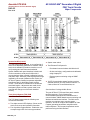
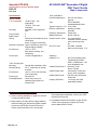
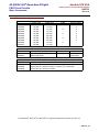
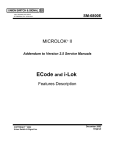
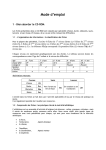
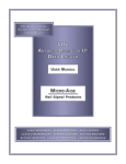
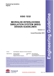
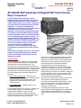
Wayside Signaling
Systems
Ansaldo STS USA
(Formerly known as Union Switch & Signal)
RSE-1F2
Rev. 4-10
®
AF-902/AF-904 Generation II Digital FSK Track Circuits
Major Components
Like its AF-900 Series predecessor, the AF902/AF-904 Generation II (AF-Gen II) Track Circuit
outperforms the functions of earlier AF-based
systems while using a much simpler configuration
of equipment house modules and track-mounted
apparatus. For example, installation and
maintenance requirements for the AF-Gen II Track
Cable Bonds are much simpler than the
impedance and mini bonds of traditional systems.
The AF-Gen II System Cardfile features a simpler
PCB arrangement than the previous AF-900 Series
unit, incorporating only two types of boards. The
original Controller PCB is replaced with a more
advanced Track Circuit System (TCS) board. This
board incorporates new Ethernet-based features
such as peer communications, integral Web
server user interface and SNMP remote
monitoring. The TCS also performs the track
transmit/receive functions of the earlier Auxiliary
board.
Most notable, existing AF-900 Series Track Circuit
cardfiles can be retrofit with the new AF-Gen II
PCBs. No rewiring of cardfile power and data
interfaces is needed.
System Cardfile
The AF-Gen II System Cardfile performs all logical
functions related to train detection, cab signal data
transmission and communications with Track
MicroLok II units, as well as conducting continuous
internal and local system diagnostics. Only six boards
are contained in the cardfile for all non-redundant (AF904-style) and redundant (AF-902-style) applications.
Only two different types of boards comprise the 6board set:
•
Track Circuit System PCB – Vital logic, track
transmissions, receptions, remote communications
(serial or Ethernet), internal diagnostics, user
configuration, track transmitter power, track
receiver circuits.
•
Power Supply PCB – Operating power for all
cardfile PCBs.
A key reliability feature of the AF-Gen II Track Circuit
is its redundant design, an essential element of
driverless train operations. In the “AF-902”
configuration, the System Cardfile incorporates
primary and back-up sets of TCS and Power Supply
boards for supervision of two track circuits.
To order, call 1-800-652-7276
e-mail: [email protected]
If the on-line “AF-902” subsystem detects an internal
fault, control is immediately switched to the off-line
subsystem. When this occurs, communications lines
with the track and both MicroLok II systems (Track
and Interlocking) are automatically switched.
For applications not requiring the degree of
redundancy afforded by the “AF-902” configuration,
the “AF-904” configuration of the AF-Gen II System
Cardfile uses the same number and arrangement of
PCBs as the 902. However, the cardfile is configured
to allow the PCBs to control up to four track circuits.
Both configurations of the cardfile automatically set
the direction of track transmissions.
Like the earlier AF-900 Series Track Circuits, the AFGen II System Cardfile is designed to perform
continuous internal and external diagnostics. In the
event of a critical failure, the system is designed to
block the transmission of cab signal data or an
indication of a clear track.
To simplify field replacement of AF-Gen II TCS
boards, each TCS board cardfile slot is equipped with
a motherboard-mounted EEPROM. This device is
used to store site-specific track circuit configuration
data.
www.ansaldo-sts.com
RSE-1F2, p. 1
Ansaldo STS USA
(Formerly known as Union Switch & Signal)
AF-902/AF-904® Generation II Digital
FSK Track Circuits
RSE-1F2
Major Components
Rev. 4-10
System Cardfile (cont’d)
•
System reset switch.
If a TCS PCB must be replaced, no re-configuring of
track circuit addressing parameter is needed. Only a
track circuit calibration procedure must be re-run to
verify settings and calculate new thresholds.
•
Two Ethernet RJ-45 ports for:
System Cardfile back panel interfaces include track
circuit connections, serial ports for MicroLok II
communications (when needed), calibration jumpers
and power input. Because of the large dynamic range
imposed by the needs of different track circuits, the
AF-Gen II System Cardfile incorporates adjustable
transformer taps for the different track receiver
circuits. These allow for variables such as different
track lead lengths. Adjustments are made via the
back panel jumpers so that a system reset is not
required with change-out of the track interface
circuitry.
Track Circuit System (TCS) PCB
User Front Panel Interfaces
The TCS board incorporates the following user
controls and indicators:
•
•
Two alpha-numeric LED displays: Show on-site
track circuit set-up and operation information.
Four 2-position toggle switches: Enable the user
to step through track circuit set-up procedures.
RSE-1F2, p. 2
•
‐
Peer-based communications with MicroLok II
‐
On-site monitoring, configuration and calibration
using a laptop PC.
‐
Remote system monitoring using an SNMP
protocol.
18 LED for monitoring system functions such as
selected direction (E or W), Ethernet channel 1 or
2 active, MicroLok II communications, etc.
User Interface Via Integral Web Server
The new AF-Gen II TCS board front panel contains
two Ethernet ports. Each of these ports
accommodates peer-based AF-GenII/MicroLok II
communications, SNMP-based remote monitoring and
Web server-based user interface. The Web server
provides a convenient way to monitor system
operation, as well as configure and calibrate AF-Gen
II system operating parameters using Microsoft’s
Internet Explorer. All front panel operations can be
performed using the Web interface.
AF-902/AF-904® Generation II Digital
FSK Track Circuits
Ansaldo STS USA
(Formerly known as Union Switch & Signal)
RSE-1F2
Major Components
Rev. 4-10
Track Circuit System (TCS) PCB (cont’d)
Track Coupling Unit
The interface shows five primary pages:
The AF-Gen II Track Coupling Unit interfaces the
track signals with the System Cardfile receiver and
transmitter circuits, and provides for tuning to the track
circuit carrier frequency. This weather-proof,
wayside-mounted unit contains two independent
coupling circuits, each consisting of a transformer (for
track voltage step-down) and a jumper-adjusted
capacitor bank for frequency tuning. Each
transformer/capacitor section serves a respective
track circuit end.
•
•
•
•
•
View Current Data: Communications with
MicroLok II, track messages, current shunt level,
track signal variance, etc.
View Configuration: Display static configuration
parameters (link to MicroLok II, Ethernet port
addresses, SNMP, track circuit ID, etc.)
View Events: Show AF Gen II system events,
warnings and critical errors.
Front Panel View: Shows all data displayed by the
front panel discrete LEDs.
Setup: Configure and calibrate AF-Gen II system
(password-protected).
RSE-1F2, p. 3
Ansaldo STS USA
(Formerly known as Union Switch & Signal)
AF-902/AF-904® Generation II Digital
FSK Track Circuits
RSE-1F2
Major Components
Rev. 4-10
Typical Coupling Unit Wayside Installation
Coupling Unit PCB Access
Track Cable Bond and Cab Loops
AF-Gen II Track Circuits use a simple but highly
effective successor to the impedance or mini bond.
This device is nothing more than a few meters of
conductive cable, typically 350 or 500 thousandcircular-mill (MCM), arranged in an “S”, “O” or “I”
shape depending on track transmission/reception
requirements for the particular installation. The end
points of the Track Cable Bond are welded to the rails;
signals are passed to and from the wayside
electronics via a parallel “Track Loop” wire used to aircouple signals to and from the heavy, rail-connected
cable.
For crossovers and turnouts, AF-Gen II Track Circuits
make use of standard Cab Loop cables, which are
better suited for the high metal content (frogs etc.) at
these locations (insulated joints retained).
Transmitting track signal currents circulating in the
cable are induced into the rails, while received signals
are induced into the cable from the rails. This type of
bond provides a strong directional vector using the
dimensional placement of the cable (total length and
width of the cable geometric shape) to set track signal
direction.
Typical “S” Track Cable Bond Application
RSE-1F2, p. 4
AF-902/AF-904® Generation II Digital
FSK Track Circuits
Ansaldo STS USA
(Formerly known as Union Switch & Signal)
RSE-1F2
Major Components
Rev. 4-10
Typical “I” Track Cable Bond Application
Typical “O” Track Cable Bond Application
Typical Cable Bond Application: Direct Injection
RSE-1F2, p. 5
Ansaldo STS USA
(Formerly known as Union Switch & Signal)
AF-902/AF-904® Generation II Digital
FSK Track Circuits
RSE-1F2
Major Components
Rev. 4-10
Track Cable Bond
Light Rail Applications:
Specifications
System Cardfile
T.C.’s Controlled:
“AF-902” style: Two
(redundant)
“AF-904”: Four (nonredundant)
Mounting:
Standard 19 inch equipment
rack
Plug-In PCBs:
6
Blank Panels:
4
Wiring:
Discrete-wire terminals for track
connections.
25-pin “D” plug for serial links.
Ethernet Connection: Two RJ-45 jacks per each TCS
PCB (8 total per cardfile)
Environment:
-25oC to +70oC
95% relative humidity, noncondensing
Power Input:
110/240 Vac @50/60 Hz
Track Coupling Unit
Mounting:
External Wiring:
Environment:
Power Input:
Field Adjustments:
Ground base, pedestal or wall.
Via “T” conduit box to internal
terminals.
-40oC to +70oC, 95% humidity
(non-condensing)
Not required.
Carrier freq. tuning via
capacitor bank jumpers on
internal PCB.
Ordering and Additional Information
•
•
Refer to ordering tabulation on page 6 for AF-Gen
II equipment part numbers.
When ordering TCS and Power Supply boards to
retrofit an existing AF-900 Series System Cardfile,
contact your ASTS USA Account Executive to
ensure a proper transition to the new boards.
RSE-1F2, p. 6
600-750 Vdc traction
(typical).
Type:
350 or 500 MCM
insulated/jacketed cable.
Typical Length (e.g. “S”) 39 ft. (12M)
Rail Elec. Attachment:
Welding via cable
terminals.
Rail Mech. Attachment: Flange clips
Ballast Placement:
Above or buried.
Neutral Connect. Point: For cross-bonding,
substation returns, catenary
poles, structure ground,
etc.
One-Turn Loop:
#12 AWG, insulated
Max. loop wire length: 15 ft
Interfaces:
Cardfile/T.C.’s:
Cardfile/Track M-Lok II:
Cardfile Power Input:
Cardfile Data D-load:
Coupling Unit/Track:
•
•
Via Tuned Coupling Units
Twisted-pair #14 AWG,
6000 ft. (1820M) max., 100
ohms impedance max.
Ethernet: RJ-45
Serial: RS-485
Commercial 110/240 Vac
source, UPS-compatible
RS-232 (9-pin) front panel
serial ports
1-turn loop, #12 AWG
(stranded/insulated)
For additional information on AF-Gen II Track
Circuit application possibilities, contact your ASTS
USA Account Executive.
For additional technical information on the AF-Gen
II Track Circuit equipment, request ASTS USA
Service Manual SM-1F2.0001.
AF-902/AF-904® Generation II Digital
FSK Track Circuits
Ansaldo STS USA
(Formerly known as Union Switch & Signal)
RSE-1F2
Major Components
Rev. 4-10
Ordering and Additional Information (cont’d)
Order No.
N12200201
N12200202
N12200203
N12200204
N12200205
N12200206
N12200207
N12200208
N12200209
N12200210
AF-Gen II Track Circuit Cardfiles
System Type
Power Input
AF-902
115 Vac
AF-902
115 Vac
AF-904
115 Vac
AF-904
115 Vac
AF-902
230 Vac
AF-902
230 Vac
AF-904
230 Vac
AF-904
230 Vac
AF-904
115 Vac
AF-904
115 Vac
Order No.
N12361001
N12360501
AF-Gen II Cardfile PCBs and Panels
Order No.
Track Circuit System PCB
N451850-2902
Power Supply PCB
PCBs
X
-X
-X
-X
-X
--
Direction Relays
X
X
X
X
X
X
X
X
---
Blank Panel
(single-width)
AF-902 and AF-904 Track Coupling Units
Order No.
N37500601
N37500603
N37500604
Coupling Unit for inductively-coupled locations (e.g. "S" bonds)
Coupling Unit for "direction-injection" locations (e.g. crossovers)
Coupling Unit for "cab loop" locations
AF-902/AF-904®, MicroLok® and MicroCab® are registered trademarks of Ansaldo STS USA, Inc.
RSE-1F2, p. 7
RSE-1F2, p. 8