1
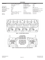
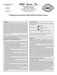
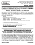
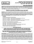
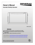
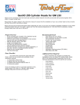
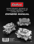
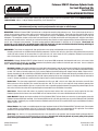
Performer RPM XT Aluminum Cylinder Heads
For Small Block Ford V8s
Part #51259
INSTALLATION INSTRUCTIONS
Please study these instructions carefully before installing your new cylinder heads. If you have any questions, please call our Technical Hotline at:
1-800-416-8628, 7:00 am - 5:00 pm, Monday through Friday, Pacific Standard Time.
IMPORTANT NOTE: Proper installation is the responsibility of the installer. Improper installation
will void warranty and may result in poor performance and engine or vehicle damage.
DESCRIPTION: Edelbrock Performer RPM XT Cylinder Heads are designed for street/strip high performance use. These cylinder heads do not have an
internal exhaust crossover and may not be legal on vehicles required to meet an emissions standard. These heads have been partially CNC machined
to produce exceptional power levels at a reasonable price. The performance range is 1500-6500 rpm for great throttle response as well as top-end
horsepower. The combustion chamber and the intake and exhaust bowls are fully CNC machined for maximum performance, while the intake entries
and exhaust exits are CNC machine "matched" for maximum flow velocity when mated to an engine equipped with the Performer RPM intake manifold,
cam kit, and a Performer Series Carburetor. This power package produced 500 horsepower in dyno tests on 351-W engines. These heads are
designed to use 1/2" head bolts. On 289-302 engines with 7/16" head bolts, you must use Edelbrock head bolt bushings with integral
washers #9680 and Edelbrock head bolt kit #8552 or stock 7/16" head bolts.
COMPONENTS: These heads are equipped with high quality beehive valve springs and lightweight valves to optimize performance.
Complete cylinder heads are assembled with the following components: Stainless steel, one-piece, 8mm stem, swirl-polished intake and exhaust
valves with under-cut stems for increased flow; LS1 style valve seals; 3/8" rocker studs and 5/16" guideplates; Edelbrock Sure-Seat Beehive
Conical Valve Springs, hardened valve spring seats, steel retainers and valve keepers.
ACCESSORIES: Although Edelbrock RPM XT Cylinder Heads will accept some OEM components (stud-mounted rocker arms, valve covers, intake
manifold, head bolts [351-W only], etc.), we highly recommend that premium quality hardware be used with your new heads. See our catalog for
details. To order a catalog, call (800) FUN-TEAM.
Head Bolts or Studs: High quality head bolts or head studs with hardened washers must be used to prevent galling of the aluminum bolt bosses.
Recommended head bolts are ARP #254-3708 for engines with 7/16" head bolt holes (289 and 302). You may use Edelbrock Head Bolt Kit #8552
or stock 7/16" bolts on 289-302 engines only if you purchase Edelbrock head bolt bushings with integral washers #9680. Engines with ½"
diameter head bolts (351-W and 302 SVO) use Edelbrock Head Bolt Kit #8553 or stock 351-W bolts with high quality head bolt washers such as
ARP #200-8533. NOTE: It is recommended that 289-302 engines producing 380 or more horsepower (or with nitrous oxide) be converted to
accept ½" diameter head bolts by a qualified machine shop to ensure maximum head gasket durability.
Rocker Arms: The valve springs supplied will accommodate valve lifts up to .600", which is much higher than stock rocker arms will allow.
Roller rocker arms will be required if your camshaft has more than .480" lift. Since the 18° valve angle will change valvetrain geometry from
stock, it is highly recommended that you use a mechanical lifter and an adjustable pushrod to determine the appropriate pushrod length (See the
table at the end of the instructions for the pushrod lengths recommended for use with Edelbrock camshafts).
Valve Covers: Because most roller rockers are physically larger than stock rockers, taller valve covers are usually required to clear them.
Edelbrock Signature Series chrome valve covers #4260 and cast aluminum Classic valve covers #4160 both work well on this head.
Intake Manifold: Although stock intake manifolds will fit, the Edelbrock RPM XT Cylinder Heads are matched in size and operating range with
Edelbrock Performer RPM intake manifolds. If the Performer RPM is too tall to fit under your hood, you may use the Edelbrock Torker II manifold
(#5021 or #5081). Additionally, any manifold that matches Edelbrock gasket #7220, or Fel-Pro gasket #1250 may be used (Edelbrock Performer,
Torker II, Victor Jr., etc.)
Exhaust Headers: Any header or manifold designed for original equipment heads will fit the Edelbrock RPM XT Cylinder Heads. Exhaust ports
are CNC-profiled to match Edelbrock #7227 or Fel-Pro #1415 exhaust gaskets, which are recommended for this application. For maximum
performance, the opening of exhaust header flange should match an Edelbrock #7227 or Fel-Pro #1415 gasket.
Spark Plugs: Use 14mm x 3/4" reach gasketed spark plugs. Heat range will vary by application from Champion RC9YC to Champion RC14YC.
The RC12YC is the plug used in the RPM applications (or equivalent). Use anti-seize on the plug threads to prevent galling in the cylinder
head, and torque to manufacturer's specification for aluminum heads.
©2010 Edelbrock LLC
Part #51259
Page 1 of 4
Brochure #63-51259
Rev. 10/10 - AJ/mc
Head Gaskets: Head gasket requirements change according to the application for which the cylinder
heads are being used. Use the following as a guide for head gasket selection. NOTE: When using
Fel-Pro Print-O-Seal, or any silicone beaded gasket, you must apply a small strip of silicone to both
the deck flange of the cylinder head, as shown to the right, and the same location on the surface of
the block to prevent coolant from contaminating the engine oil.
1.
Engines with low or stock compression ratios (8-10:1), stock size head bolts (7/16"), and
applications where the cylinder head is being used as a stock replacement or a performance
upgrade with the stock piston volume, without nitrous or forced induction (blowers or turbos) use Edelbrock head gasket #7313 or Fel-Pro Head Gasket, #9333-PT1.
2.
Medium performance engines, 10-12:1 compression ratio, increased pre-load cylinder head fasteners (7/16" stud or ½" head bolts or studs),
not recommended with nitrous or forced induction - Edelbrock head gasket #7313 or Fel-Pro Head Gasket, #1011-2.
3.
Highest performance racing engines. 12:1 and above compression ratio, ½" cylinder head fasteners designed for the highest pre-load,
engines using nitrous or forced induction - Fel-Pro Head Gasket #1006 Locwire. NOTE: This gasket will require a groove to be cut in the
deck surface of the cylinder head by a competent machine shop to Fel-Pro specifications. See “OTHER ASSEMBLY TIPS:” below.
NOTE:
For applications 1 & 2 above, Edelbrock Cylinder Head Gasket Set #7364 may also be used. This gasket set includes all gaskets necessary
for installation of Edelbrock cylinder heads, including cylinder head, intake manifold, exhaust, and valve cover gaskets.
INSTALLATION: Before final installation of the cylinder heads, several things need to be checked to assure proper engine operation:
1. Check the upper deck to see if you have an early or late model block (not needed with 351-W): a) Late model 289-302 blocks have the water
passages located next to the head bolt location on the deck of the block (This block will not require drilling). b) Early 289-302 blocks will
have the water passages located directly over the cylinder upper deck area and will require drilling 1/8" steam holes in the block as seen in
Figure 2.
2.
Piston to Valve Clearance - Minimum intake valve clearance should be .080". Minimum exhaust valve clearance should be .110". The
point of minimum intake valve to piston clearance will usually occur somewhere between 5° and 20° ATDC during valve overlap. The point
of minimum exhaust valve to piston clearance will usually occur 20° to 5° BTDC during valve overlap. Due to the 18° valve angle, remachining of the piston top eyebrows may be required with some pistons.
3.
Proper Hydraulic Lifter Pre-Load and Rocker Geometry - Rocker geometry should be checked making sure that the contact point of the
roller or pad on a stock rocker remains properly on the valve tip and does not roll off the edge. Visual inspection of the rockers, valve springs,
retainers, and pushrods should be made to ensure that none of these components come into improper contact with each other. If problems
with valve train geometry occur, simple changes such as pushrod length may have to be made. Refer to the table at the end of the instructions
for recommended pushrod lengths.
OTHER ASSEMBLY TIPS:
•
When installing the sparkplugs and exhaust manifolds, be sure to use a high temperature anti-seize compound on the threads to reduce the
possibility of thread damage in the future.
•
Do not exceed a torque of 16-18 ft.-lbs. on the intake manifold bolts and lubricate the bolt threads prior to assembly.
•
If pushrod to cylinder head contact is a problem, loosen rocker studs and re-position guideplate as needed for clearance.
•
Installation is the same as for original equipment cylinder heads. Consult service manual for specific procedures, if necessary. Head gasket
recommendations are listed in the head gasket section. Be sure that the surface of the block and the surface of the head are thoroughly
cleaned to remove any oily film before installation. Use alcohol or lacquer thinner on a lint-free rag to clean. Apply moly-oil mixture to head
bolt threads, washer, and area under head bolt to prevent galling and improper torque readings. Torque to 70 ft.-lbs. for 7/16" bolts (289/302)
or 100 ft.-lbs. for ½" bolts (351-W) in three or four steps following the factory tightening sequence (see Figure 1), then tighten the long (upper)
head bolts to 80 ft.-lbs. (7/16") or 110 ft.-lbs. (1/2"). A re-torque is recommended after initial start-up and cool-down (allow 2-3 hours for
adequate cooling).
©2010 Edelbrock LLC
Part #51259
Page 2 of 4
Brochure #63-51259
Rev. 10/10 - AJ/mc
SPECIFICATIONS
Head Bolt Torque:
Intake Bolt Torque:
Rocker Studs:
Rocker Stud Torque:
Combustion Chamber Volume:
Intake Port Volume:
Exhaust Port Volume:
Deck Thickness:
Valve Seats:
Valve Size:
Valve Locks:
Valve Spring Retainers:
Valve Spring Diameter:
Valve Spring Installed Height:
Valve Spring Seat Pressure:
Max. Valve Lift:
Pushrod Guideplates:
Rocker Arms:
7/16" bolts - 70/80 ft.-lbs. (short/long
bolts) 1/2" bolts - 100/110 ft.-lbs.
(short/long bolts)
16-18 ft.-lbs.
7/16"
45 ft.-lbs
58-60cc
185cc
60cc
5/8"
Hardened, interlocking ductile iron,
compatible with unleaded fuels
Intake - 2.02", Exhaust - 1.60"
8mm x 7°
Pushrods:
Spark Plugs:
Recommended Intake Gasket:
Recommended Exhaust Gasket:
7° 4140 steel
1.300"
1.800"
138 lbs.
.600"
5/16" Hardened steel
Will accept stock (except rail style) or
aftermarket roller type
Will require 5/16" hardened pushrods for
use with guideplates
14mm x ¾" reach gasketed seat
Fel-Pro #1250
Fel-Pro #1415
9
5
1
3
7
10
6
2
4
8
Figure 1 - Head Bolt Tightening Sequence
1/8” Holes Drilled
into the Water Jacket.
Position Hole Location
Using the Head Gasket.
#5 Cylinder
Front Cylinder
LH Bank
(Driver Side)
These diagrams depict
the deck surface of the
block. DO NOT drill into
the deck surface of the
cylinder heads.
#1 Cylinder
Front Cylinder
RH Bank
(Pass. Side)
Figure 2 - Steam Hole Locations for Early 289 & 302 Engine Blocks
©2010 Edelbrock LLC
Part #51259
Page 3 of 4
Brochure #63-51259
Rev. 10/10 - AJ/mc
RECOMMENDED PUSHROD LENGTHS
IMPORTANT NOTE: The lengths supplied in the table below are for use with Edelbrock and Scorpion brand roller rocker arms, with a ratio of 1.6:1.
Crane roller rocker arms will require pushrods that are .100” longer than the dimensions supplied below, other brands may have different variances.
Use of an adjustable pushrod to determine the specific length required by your application is recommended. Be sure to verify your valvetrain geometry
by turning the crankshaft through 720° degrees of rotation, while checking that all rollers maintain sufficient contact with the valve tips. The dimensions
supplied below are a recommended starting point ONLY; be sure to verify proper operation and sufficient valve clearance before starting the engine.
Edelbrock Camshaft
Part Number:
Intake Base Circle
Exhaust Base Circle
Recommended Intake
Pushrod Length
Recommended Exhaust
Pushrod Length
2221
1.315”
1.315”
6.350”
6.450”
7122
1.385”
1.360”
6.900”
7.000”
2281
1.287”
1.302”
7.650”
7.750”
7182
1.390”
1.360”
8.250”
8.350”
Edelbrock, LLC • 2700 California St. • Torrance, CA 90503
Tech Line: 800-416-8628 • Office: 310-781-2222
©2010 Edelbrock LLC
Part #51259
Brochure #63-51259
Rev. 10/10 - AJ/mc